
The LHD Digidash Bible
- Thread starter Pyro15D
- Start date
You are using an out of date browser. It may not display this or other websites correctly.
You should upgrade or use an alternative browser.
You should upgrade or use an alternative browser.
Well you all, lets see if this next post can help ")
Today while the carpet installers are installing the carpet downstairs I decided to see if I could modify my stock fuel sending unit to work with the new gauge cluster. When you pull the stock sender out, bend back the three tabs that hold the little tin cover on. After you get that done, you should have something that looks like this.

Before you go any further, I want to remind you that this assembly has most likely been sitting immersed in fuel. I would recommend that you spray the sending unit with electrical parts cleaner and let it dry completely. You don't want to be catching yourself on fire here. :: angry :: Also, I get the feeling I need to say this as well. Don't do this around the gas tank. Anyway, now that my conscience is clear, lets move on.
See the wire that is soldered to that post? you can see it curling around the rod down to the Low Fuel Warning Sensor. Unsolder the wire from the post and unscrew the two screws that hold the post on. That whole assembly isn't needed for the digital dash.
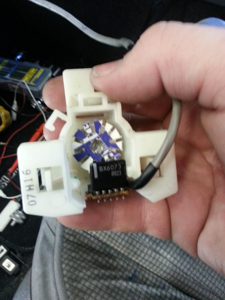
Now, flip the whole assembly over, You will see 2 more posts at the top. One is connected to a piece of metal leading to the resistance circuit and the other is connected to a green wire going to the wiper assembly. For a reference, see below. JDM sensor is on the right, the sensor we are working on is on the left, with the yellow sleeve over the harness:

Now, if you look closely, you will see a notch in the top right side of the resistance board. Take a look at this picture for help:

Sorry, I had to do all this in photobucket and apparently you can't draw straight lines in the editor.:3d_frown: Anyway, that notch is there to hold the end of the resistance wire to prevent the whole coil from unwinding. You will need to take a small flathead screwdriver (like a jewelers screwdriver) and pop out the wire so you can unwrap it ONE revolution. When you are done, it should look like this:

The camera had a hard time focusing on just the single strand of wire, but hopefully you can see what I'm talking about. Now, that wire is covered in an enamel coating for insulation. You will need to take some 300-400 grit sandpaper and CAREFULLY sand off the insulation about 1/4" from the end. It will look shiny when you have removed the enamel.
Remember the green wire that went to the wiper? You are going to unsolder that wire and solder it to the post that the Low Fuel sensor was hooked to. It should look like this when you are done:

Now, flip it back over so you the resistance board and wiper assembly is facing you. Take that sanded piece of wire and solder it to the post that the green wire was formerly connected to. It should look like this when you are done:

At this point, that resistance wire can gradually slack up. You don't want that. What you will want to do is apply some gasoline-safe adhesive to the backside (the side away from the wiper arm; don't let anything get on the wiper arm or the wire surface that it actually wipes) so that the wire remains coiled up nicely. I used Eclectic adhesive from Autozone.
Now, you may want to plug it in the tank and enjoy your working digital dash fuel gauge. Don't. The pinout is different and you don't want to fry the gauge (smoke) or the sender (boom). You need to swap 2 pins over. As you are looking at the sender connector (male pins facing you), top left is Yellow with a Green stripe, top right is White with Black stripe, bottom left is Black, and bottom right is Red with Blue stripe. If you look closely, the connector is a front-release connector, which for this situation means that you can take a small jewelers flathead and going above the pin, lift the plastic tab holding it in and pull it out the back. Do it for the top left and bottom right pins. When you are done, it should look like this:

Now switch places of them. It should look like this now:

Put the Red with Blue stripe wire in the top left and the Yellow with Green stripe in the bottom right. Place the tin cover back on the sender and it should resemble this:

Install the sender back in the tank. If your tank is a couple gallons short of full (like mine is) it should look like this:

and save you from having to source (and overpay for) a ridiculously hard to find part. Enjoy!
Today while the carpet installers are installing the carpet downstairs I decided to see if I could modify my stock fuel sending unit to work with the new gauge cluster. When you pull the stock sender out, bend back the three tabs that hold the little tin cover on. After you get that done, you should have something that looks like this.
Before you go any further, I want to remind you that this assembly has most likely been sitting immersed in fuel. I would recommend that you spray the sending unit with electrical parts cleaner and let it dry completely. You don't want to be catching yourself on fire here. :: angry :: Also, I get the feeling I need to say this as well. Don't do this around the gas tank. Anyway, now that my conscience is clear, lets move on.
See the wire that is soldered to that post? you can see it curling around the rod down to the Low Fuel Warning Sensor. Unsolder the wire from the post and unscrew the two screws that hold the post on. That whole assembly isn't needed for the digital dash.
Now, flip the whole assembly over, You will see 2 more posts at the top. One is connected to a piece of metal leading to the resistance circuit and the other is connected to a green wire going to the wiper assembly. For a reference, see below. JDM sensor is on the right, the sensor we are working on is on the left, with the yellow sleeve over the harness:
Now, if you look closely, you will see a notch in the top right side of the resistance board. Take a look at this picture for help:
Sorry, I had to do all this in photobucket and apparently you can't draw straight lines in the editor.:3d_frown: Anyway, that notch is there to hold the end of the resistance wire to prevent the whole coil from unwinding. You will need to take a small flathead screwdriver (like a jewelers screwdriver) and pop out the wire so you can unwrap it ONE revolution. When you are done, it should look like this:
The camera had a hard time focusing on just the single strand of wire, but hopefully you can see what I'm talking about. Now, that wire is covered in an enamel coating for insulation. You will need to take some 300-400 grit sandpaper and CAREFULLY sand off the insulation about 1/4" from the end. It will look shiny when you have removed the enamel.
Remember the green wire that went to the wiper? You are going to unsolder that wire and solder it to the post that the Low Fuel sensor was hooked to. It should look like this when you are done:
Now, flip it back over so you the resistance board and wiper assembly is facing you. Take that sanded piece of wire and solder it to the post that the green wire was formerly connected to. It should look like this when you are done:
At this point, that resistance wire can gradually slack up. You don't want that. What you will want to do is apply some gasoline-safe adhesive to the backside (the side away from the wiper arm; don't let anything get on the wiper arm or the wire surface that it actually wipes) so that the wire remains coiled up nicely. I used Eclectic adhesive from Autozone.
Now, you may want to plug it in the tank and enjoy your working digital dash fuel gauge. Don't. The pinout is different and you don't want to fry the gauge (smoke) or the sender (boom). You need to swap 2 pins over. As you are looking at the sender connector (male pins facing you), top left is Yellow with a Green stripe, top right is White with Black stripe, bottom left is Black, and bottom right is Red with Blue stripe. If you look closely, the connector is a front-release connector, which for this situation means that you can take a small jewelers flathead and going above the pin, lift the plastic tab holding it in and pull it out the back. Do it for the top left and bottom right pins. When you are done, it should look like this:
Now switch places of them. It should look like this now:
Put the Red with Blue stripe wire in the top left and the Yellow with Green stripe in the bottom right. Place the tin cover back on the sender and it should resemble this:
Install the sender back in the tank. If your tank is a couple gallons short of full (like mine is) it should look like this:
and save you from having to source (and overpay for) a ridiculously hard to find part. Enjoy!
Nice job Sir. Question, does the digi dash have a mechanical odometer? It looks mechanical in the pictures. I see the tripmeter is electronic though.
Pi, the digidash uses a mechanical one driven by a stepper motor. The motor is controlled via a driver on the main board. Kind of an interesting solution really.
Not sure if this would help, but I came across this for the MPH reading fix: http://www.clickdesign.co.uk/supradupra/html/kph_to_mph.html
A-to-the-J, I am probably going to do that. I have a spare main display board so I'll make the modifications to light up the correct legends and buy the 8:5 ratio electronic speed converter for the vehicle speed sensor. The converter is around $60, so I guess it is a small price to pay to have a dash that shows the correct speed. What I really liked about this swap though is my cruise control finally works!::w00t:: I think while I have my dash out, I will wire up the ECON, PWR and MANU lights to my HKS EVC1 so when I hit the buttons for the different boost levels, the corresponding light will come on in the dash. Kinda dumb, but I like the idea. Those lights are for the automatic transmission as far as I know, and I'm running a manual. Anyway, while I was walking around the junkyard yesterday, I found a late 80's Subaru GL-10 (Loyale I think) with a digital dash in it. I pulled the dash out, and lo and behold, it is made by Nippondenso! It has a very similar digital speed sensor with the 20-slot wheel. It even had the mostly the same part number on the board, 457652. The supra one is 457652-2002 and the subaru one was was 457652-2167 (I think). Anyway, they are mostly the same layone but more importantly, the Subaru one has a jumper on a 2-pin socket. When you pull the jumper off, the gauge switches from MPH to KM/H as well as the ratio. I verified this by hooking the speed sensor to a drill and spinning it. With it on MPH, I read 62 MPH and with KM/H it showed 105 KM/H. I followed the trace back to pin 19 on the Toshiba TC9500AP-814. It is a large 64-pin IC and if that pin is brought low, it switches from KM/H to MPH. I'm guessing it is some sort of microprocessor, but I can't find a data sheet online. I'll do some more digging today and see if I can find something on it. It would be awesome if that was the case though, because it is probably similarly designed on the Supra board and maybe I can make it work.
Edit: I think the chip number on top is a proprietary number. I think it is actually TMP87C814, which would make sense since it is an 8-bit microcontroller combined with a VFD driver. Now, to figure out how to get the Rom image off...
Edit: I think the chip number on top is a proprietary number. I think it is actually TMP87C814, which would make sense since it is an 8-bit microcontroller combined with a VFD driver. Now, to figure out how to get the Rom image off...
Last edited:
Interesting info on the processor. The danger is the MCU is proprietary, and therefore there aren't any publicly available development tools. That was the case for the ECU where the MCU is also fab'd by Toshiba.
Maybe I am missing the point, but isn't there a different speedo adapter you can put in the tranny to make the change? Also, what does the odometer do? Is it in kms or miles?
Maybe I am missing the point, but isn't there a different speedo adapter you can put in the tranny to make the change? Also, what does the odometer do? Is it in kms or miles?
Well, the way the system is set up, the standard cable runs from the trans all the way up behind the dash to the speed sensor. The sensor has a 20 tooth optical wheel on it. Now, the odometer is in kms along with everything else. I could just cut the pins tha illuminate the KMS and KM/H legends and reroute the power to the MILES and MPH legends, then either make a 12-tooth optical wheel or find an electronic speedo converter from here or here to down convert the frequency to MPH. Since the stepper motor odometer is driven off of the speed signal from the sensor, dropping the ratio with the converter would automatically make it read correctly. I will probably just do this option since it seems to be the most idiot proof, but I was hoping that I could somehow reverse engineer the board a bit and maybe discover a pin that if brought low (or high) would switch it over to MPH like the Subaru dash. I guess these dashes are like apples to oranges though. I was hoping for something more like fuji apples to granny smith apples.
You know, I never checked! I have a multimeter that has a frequency function. I'll check it out!
Sent from my SCH-I535 using Tapatalk
Sent from my SCH-I535 using Tapatalk
Excellent writeup. It's not often I'll agree to sticky something in the general section.
How did you deal with converting the terrible plugs on the stock harness to the plugs for the digital dash? Splice in the new plugs? Or did you put together some kind of patch harness?
How did you deal with converting the terrible plugs on the stock harness to the plugs for the digital dash? Splice in the new plugs? Or did you put together some kind of patch harness?
Awesome, thanks everyone! Dave, I have this big issue with doing modifications I can't undo, so for this I just spliced into the existing harness and kept all the old connectors. My thoughts were that if I ever wanted to switch back to the analog dash, I remove the digital cluster, speed sensor, swap out the fuel sender to the analog one, and install the old dash. Shouldn't take more than half an hour then it goes back to stock! I might start modifying the stock harnesses for the digital dash if there is enough interest. I have to finish selling the house though. It went on the market yesterday.
Nice work my friend! I love the finished result! We all get there in our own way and you did quite a nice job. I approve of this thread.
Eric
Eric
Hey thanks a lot Eric! I took a lot of info from your thread and without it, I couldn't have done what I did! Hopefully some of the info here will be helpful to you as well. I would like everyone else who does the conversion to post a picture of their completed swap on this thread someday too. I think that would be pretty nice.
Sent from my SCH-I535 using Tapatalk
Sent from my SCH-I535 using Tapatalk
So now everything is working great but I can't leave well enough alone. Living in the US and being stuck with gauges that read in KPH is a bit of an inconvenience. Well, this past week I rectified the situation. First, I used the instructions found here and lit up the correct legends. Now, that doesn't do any good if the numbers displayed aren't accurate! To fix that, I had to modify the speedo sensor. The stock one looks like this, with a 20-slot disk.

Now, I figured if I just made a disk with a fewer number of slots, it would display the correct number. for that, I noticed that 60mph is really close to 100kph. Divide both those numbers by 5 and you are left with 20 and 12. If I made a disk with 12 slots vs 20, it should display the correct speed. I designed one on this website and crudely cut one out of some plastic that I had laying around. It isn't the most pretty solution as you can see here:
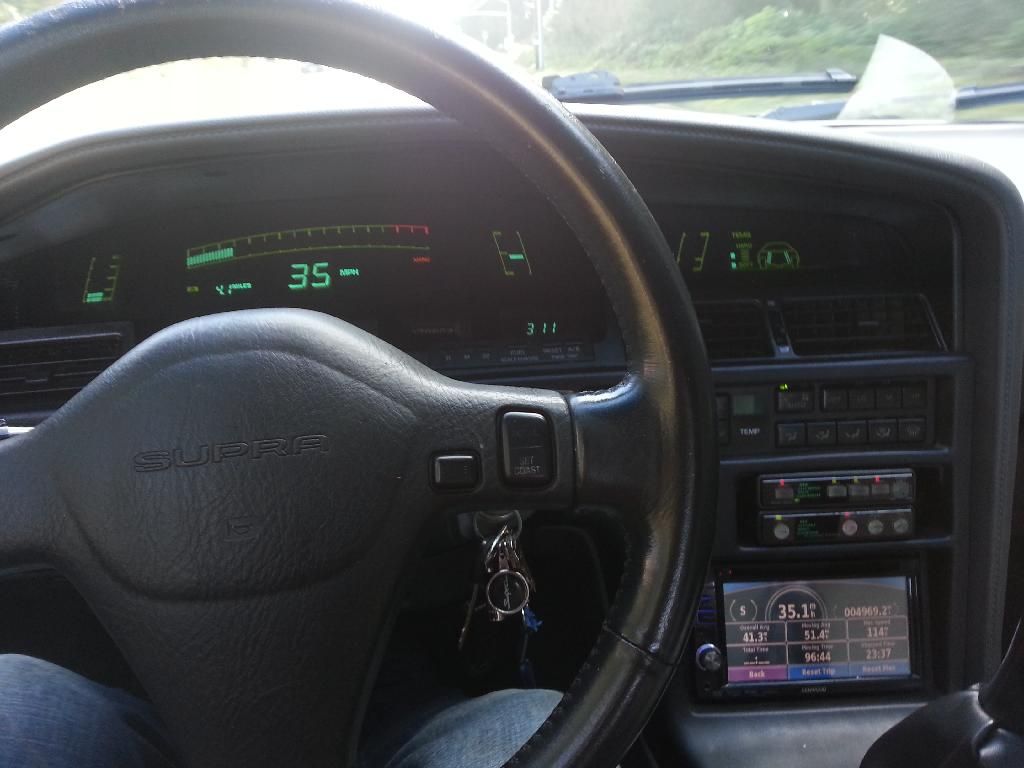
I know it doesn't look the best, but after I put it all back together, I went for a drive and verified the speed with the GPS on my headunit. It works!

100 kph = 62 mph (basically)
kilometers x 0.6214 = miles
Funny that Toyota never gave us a digital dash... lol.
I grew up with imperial numbers... and in Grade 7 had to convert to metric. Of course.. your Peanut Farmer President decided... whoa... too tuff... so... you guys had it only for a short blink.
It was cool because our 60mph speed limits became 100... so as a teenager, we thought that was a good excuse to race.
It is funny that they didn't. Probably had something to do with health and safety BS. I have developed this irrational hatred towards you guys with your awesome cars that you can get now. We still have to wait 10 more years to get the R34 and such. Grumble Grumble...