morganson's COP S-Type setup

AbsoluteSpeed

Member
Aug 8, 2007
735
0
16
Edmonton AB
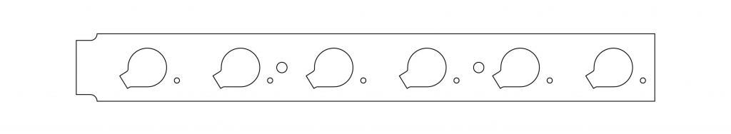
Alright, I made the changes I needed to.
I also made the mounting hole 5mm diameter so it can be tapped for a M6-1.00 bolt (same bolt ford uses). If you want to mount the coil under the bracket all you need to do is drill this hole out to 1/4" and use a nut and bolt to secure it but, you will have to file down a little plastic on the coil it self.

I have one small issue that is making me second guess myself. I drew this with the coil centered in the bracket but now that I have an coil in hand I noticed the boot is offset. See the picture below, the 'X' shows roughly where the boot is.

p1983284_1.jpg


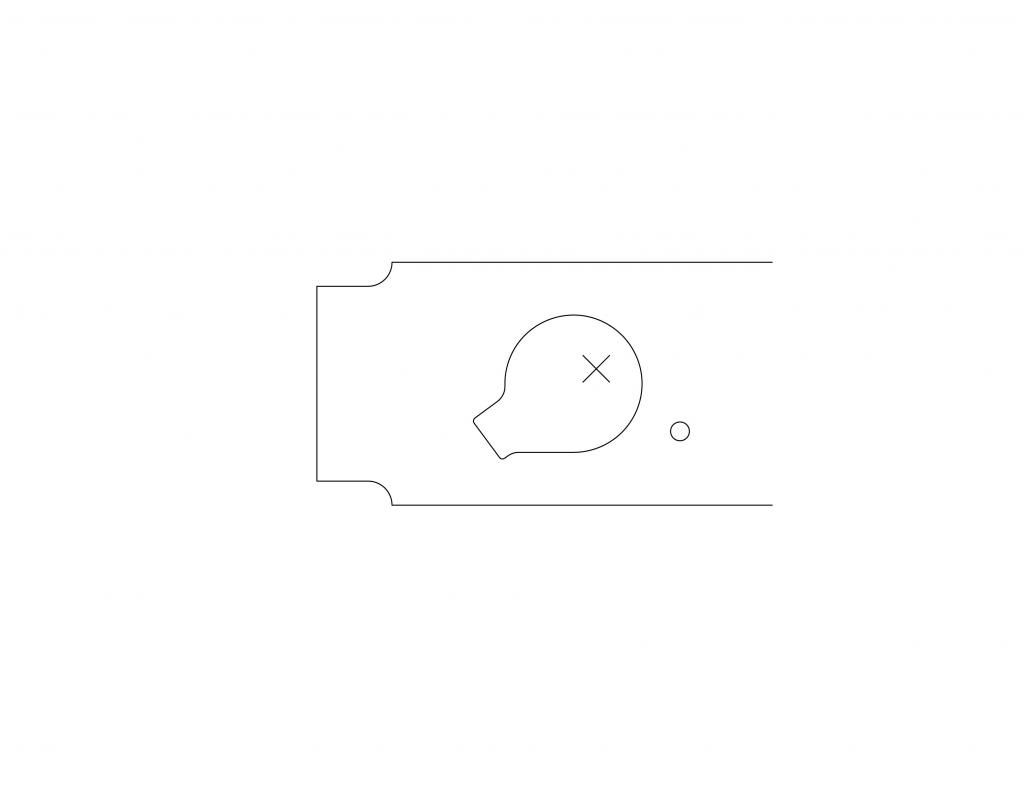
This would mean the sparkplugs aren't centered in the head, and that just doesn't seem right to me.
I'd like Morganson to print that pic and make sure everything lines up with the one he made. (To ensure proper scale use regular 8-1/2"x11" paper and make sure you turn off "Fit to Paper" when you print).
If he can do that and everything lines up we can get this shit done!
 

Black Cat

Member
Sep 11, 2009
62
0
6
Fort Bragg NC
Okay this is the thing I don't get and I see it has been asked a couple of times now, but wired up in series like that isn't each coil only getting 6 volts?
When these are designed to run off of 12 volts I may be a little rusty but wouldn't it take twice as long to build up the needed amperage at 6 volts vs 12 volts?
As grim was saying the coils never got a chance to reach there full charge except at idle, If you guys have tried this setup before just call me an idiot for not seeing that post.
7hC0QcH.jpg I tried to keep the same colors from your original diagram.
Now the other thing is that running it like that will double the amperage because you will be halving the resistance, just give me a sec to work out the figures.
So never mind on that part seeing as with the figures I've found and what grim has posted the stock Toyota coil pack is a 30 amp circuit two fords in parallel
would only be about 24 amps, that is if the figures given by grim are .9 to 1 ohm per coil, if that is the ohms for two in series then that makes the two fords
in parallel a 48 amp circuit.
The current set up would be just a 6 or 12 amp circuit depending if the fords are .5 ohms each or 1 ohm.

Note if any of this is wrong please let me know how and what is wrong.
 
Last edited:

supraguy@aol

Well-Known Member
Dec 30, 2005
4,232
37
48
Atlanta
Looks like you simply switched from series to parallel setup. Not sure if the resistance change affect the igniter's ability to trigger the coils or not.

Thanks for the update, AbsoluteSpeed.
 

Black Cat

Member
Sep 11, 2009
62
0
6
Fort Bragg NC
Well as far as I know the igniter just connects the circuit to ground to start the charging of the coil and disconnects the ground to fire it.
running in parallel gives each coil 12 volts running in series only gives them 6 volts each.
 

AbsoluteSpeed

Member
Aug 8, 2007
735
0
16
Edmonton AB
Grim tried running this in parallel but dwell was worse and Morgansons had originally tried to wire his in parallel but it just wouldn't run.

grimreaper;1982107 said:
I did, lol. Cant sleep when something goes unanswered!

Ran the ford coils with polarity hooked up both ways in parallel and in series. Only way it works is if the 12v+ is on the right pin and they are in series. Swapping polarities drastically reduced the charge time but missfired when free reved.

parallel works but very very poorly. Dwell significantly reduced, less than 1ms.

Which pins are you guys putting 12v/gnd to?
 

pete05

New Member
Nov 24, 2012
64
0
0
australia
In reference to what AbsoluteSpeed has mentioned above about coil placement this is why I have mine like this. coil number 4 does need to be rotated about 130 degrees so the plug on the coil pack clears the cross over pipe. Also worth a mention is my coils sit slightly higher the original design.


And the charge time seems to be ok, my plugs look good at 12psi boost. The extra current draw on the ignitor is my only long term concern, the car feels very strong and smooth with the coils though.
 

AbsoluteSpeed

Member
Aug 8, 2007
735
0
16
Edmonton AB
It's done.
p1984250_1.jpg


Doesn't look much different but I redrew the coil and then changed it about ten times until I was happy with it.
I made sure you can mount the coils both on top and from underneath (will be a close fit when you mount them from the underside and, like I mention before, you will have to file down a little plastic on the coil but it should work just fine).

nathaninwa;1982988 said:
I can do them anytime. I just need the .dxf file emailed to nathaninwa @ gmail.com I do have a head to test them on, just no coils.
Ill be sending you the CAD file right away. Just forgot you wanted a .dxf

pete05;1983415 said:
In reference to what AbsoluteSpeed has mentioned above about coil placement this is why I have mine like this. coil number 4 does need to be rotated about 130 degrees so the plug on the coil pack clears the cross over pipe. Also worth a mention is my coils sit slightly higher the original design.
http://i8.photobucket.com/albums/a16/pete05/copmods_zps8f97cc82.jpg

And the charge time seems to be ok, my plugs look good at 12psi boost. The extra current draw on the ignitor is my only long term concern, the car feels very strong and smooth with the coils though.
http://i8.photobucket.com/albums/a16/pete05/20131126_115148_zps23e5a089.jpg

Did you use the full uncut boot on your coils? Is that why the fourth coil has to be rotated?
 

pete05

New Member
Nov 24, 2012
64
0
0
australia
No the boots are cut, I kept the gasket plate that the original plug lead boots clip into so that is as low as the coils will sit with that plate still in place, when I looked at the way you have it drawn up I could not see how you could get the coil centred over the plug without the coil body fouling on the head even with the gasket plate removed.
 

AbsoluteSpeed

Member
Aug 8, 2007
735
0
16
Edmonton AB
pete05;1984253 said:
No the boots are cut, I kept the gasket plate that the original plug lead boots clip into so that is as low as the coils will sit with that plate still in place, when I looked at the way you have it drawn up I could not see how you could get the coil centred over the plug without the coil body fouling on the head even with the gasket plate removed.

Hmmmm. I was just going off Morgansons example so I haven't had a chance to try this out for myself. Hope it works out :eek3:

nathaninwa I just sent you the file.

Last thing, I was worried about the boot not lining up with the plug because of the way the coil is rotated. It is slightly off but only by about 3mm, so I left it that way. Call it OCD but it would have bugged me to see the coils off center.
 
Last edited:

lithium14

Member
Jan 7, 2011
995
0
16
Austin
Hey guys I was just working on my own 7M and a thought occurred to me. Idk if it was addressed in the thread, if so, I'm blind.

How does the throttle linkage assembly fit over all this?? Does anyone have some close up pics?
 

morganson

New Member
Jan 19, 2012
274
0
0
Columbia, SC
I cut the post that goes down to the galley off all together. Doesnt affect the linkage at all. However it might be possible to clear the coil if you dont want to cut it. I will have to double check. But mind you it is close.
 

nathaninwa

New Member
Jul 1, 2012
377
0
0
Aberdeen, WA
I want to test fit the coil tomorrow, then I can cut another one and get them to you Monday. Then maybe you can fit in car and then I can cut the rest?