Miekedmr's build thread

miekedmr

mkiii in hibernation
Jul 12, 2005
511
0
0
Upstate NY
QcU8N9r.jpg

I'm not sure why that looks all sepia like instagram. Glare from the sun, I guess.

cooJ4yf.jpg

Just a couple of really low quality pictures of engine/trans before "final assembly", and this:

paQ94sj.jpg
 

miekedmr

mkiii in hibernation
Jul 12, 2005
511
0
0
Upstate NY
IMG_20140322_140741_731.jpg
Nice day for work.

IMG_20140322_140800_342.jpg
dremeled off the now-unused fuel return line

IMG_20140322_161815_780.jpg

IMG_20140503_225248_685.jpg

IMG_20140504_114444_576.jpg
I needed to connect these two pipes since the oil-to-water cooler is gone.

IMG_20140504_120545_551.jpg

IMG_20140504_140633_933.jpg

IMG_20140504_141641_926.jpg
I made a brace for the location the PS pump normally would attach to the AC compressor. (Inspired by someone else on here..)
 
Last edited:

miekedmr

mkiii in hibernation
Jul 12, 2005
511
0
0
Upstate NY
IMG_20140504_154212_847.jpg

IMG_20140504_160629_363.jpg
Ugly dipstick brace, but it works.

IMG_20140504_173139_806.jpg

IMG_20140504_183756_156.jpg

IMG_20140504_183810_148.jpg
This will be the return from the oil pressure regulator hooked up to the external 12v oil pump.

IMG_20140504_184844_041.jpg

IMG_20140505_130859_218.jpg
Mounting the oil cooler was made pretty easy by the modified rad support.

IMG_20140505_130840_105.jpg

IMG_20140505_131440_651.jpg

IMG_20140505_131818_273.jpg
I started seeing flashes, so..
 
Last edited:

miekedmr

mkiii in hibernation
Jul 12, 2005
511
0
0
Upstate NY
IMG_20140505_140937_826.jpg

IMG_20140505_140952_291.jpg]
Mounted.

IMG_20140505_145020_817.jpg
AN-14 (7/8") fit here to replace the ripped original. The pipes needed to be bent a little to line up with the flange on the pan.
 
Last edited:

miekedmr

mkiii in hibernation
Jul 12, 2005
511
0
0
Upstate NY
Fuel pressure is 42psi, no leaks.

Theres about 2.5qt of extra oil capacity with the cooler and plumbing for the 12v oil pump.
Oil flows through the engine when I run the 12v pump, which I used to pressurize the oil system prior to turning it over with the starter.

Starter is wired and works.

I'm going to work on getting the ECU wired now and see if I can pop it off!
 

Attachments

  • 42psi.jpg
    42psi.jpg
    136.3 KB · Views: 19

miekedmr

mkiii in hibernation
Jul 12, 2005
511
0
0
Upstate NY
I actually held off on trying to start the engine since the gas in the tank is really old. That will need to be drained and filled with fresh stuff, then I'll probably run the pump a little to get the old stuff out of the rail...

Here are some pictures of the shifter I made:

shifter1.jpg

shiftersh.jpg
high temp cloth shielding so I don't burn the rubber.

shifter2.jpg
welded and installed.

I figure that will be frowned upon, but that's ok! I actually like the throw and position of it, having sat in the drivers seat and pretend drove a little bit.
 

miekedmr

mkiii in hibernation
Jul 12, 2005
511
0
0
Upstate NY
I hatched a plan to deal with the hole I cut there in the trans tunnel:

1. Cut a rectangular section out of the trans tunnel of my parts car, around the stock shifter hole, big enough to cover the "affected region"

2. Clean up the metal, strip paint/undercoating.

3. Tack the tunnel section from the parts car into place about 2-3" above where it normally sits to make room for my wonky shifter, using some thin steel rod in each corner.

3. Lay some CF sheet (I have a roll of it) and epoxy resin over the gap all the way around, top and bottom.

What I should end up with is a raised section of trans tunnel with a stock shifter hole just a few inches higher than where it is normally. That way I can still use the oem rubber boot.
 

miekedmr

mkiii in hibernation
Jul 12, 2005
511
0
0
Upstate NY
It's worth noting on my last trip I went back and did a more thorough welding job on the kinked shifter, it's now pretty beefy around that joint and shouldn't bend or break on me.

I'm making a trip this weekend to do some more work on my car... Stuff I have left to do:
1. splice, solder and heat shrink the JZX90 engine harness into a spare 7M harness so it mates up with my body plugs... get the injectors to fire.
2. install the radiator/silicone coolant hoses I ordered, cap off the heater lines temporarily, fill with coolant.
3. a little bit of reconfiguring of my oil lines and hooking up a pressure sender.
4. install intercooler and piping.
5. finish modding the trans tunnel so I can install the rubber boot and interior bits
6. install electric speedometer, which I ordered the other day:
gauge.jpg

The face of that speedo will match my other gauges somewhat, because it's white faced (correction, gauge face is silver. Oh well.) but will be a bit different in other respects (lighting, style)
I actually think I will enjoy having mismatched gauges... it says "function first, form second"
We'll see how much I can do in a couple days. :)
 
Last edited:

miekedmr

mkiii in hibernation
Jul 12, 2005
511
0
0
Upstate NY
It sounds good with the exhaust on too. :)
I have it mounted now but haven't taken any pictures or video yet.
It's the same exhaust previous owner had on the car which was 3" (if I remember right) catback+cat, with my addition of the driftmotion DP for 1JZ+stock twins. Everything bolted right up.

I've made some progress with wiring, too, and deleted the traction control hardware from the throttle body:

delete left.jpg

delete right.jpg

traction control delete.jpg
 

miekedmr

mkiii in hibernation
Jul 12, 2005
511
0
0
Upstate NY
The radiator is now part of the way mounted underneath the cross piece that the hood latch attaches to. I need to make some better brackets to hold the bottom up, but the uppers fit nicely. I had to do a little rerouting of the loom to get it out of the way of the radiator. Mounting the radiator the way I did is only possible because of previous modifications made to make room for the TT 1UZ.

This gives me some extra room between the radiator and the engine. The reason I want extra room there is:

fittings.jpg

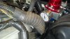
These will be sitting between two 4x8" barrel style water to air intercooler cores, with 2.25" inlets and outlets. Each is said to "support" 290hp.
[EDIT: no they won't. the 1/2" NPT ports were not lined up well enough on the two intercooler cores to connect them with these T pieces, but they will still get used...]

cooler.jpg

Why two small intercooler cores instead of a roughly equivalent but easier-to-route single 6" round core or similar?
The 4"s fit between the engine and radiator, A 6" doesn't.

Why put them behind the radiator?
A short intake tract with low volume should improve throttle response and keep pressure drop low compared to an FMIC. It's debatable but I'm doing it, so we'll see!

Won't they get heat soaked?
I will be insulating them as well as I can and pumping as much cool fluid through them as I can to minimize this. The pump does 20GPM free-flowing and will be connected with -12AN.

You're doing this for stock twins??
Stock twins, especially, will benefit from lower pressure drop and as cool of an intake charge as possible. It means they don't need to work as hard to produce the same pressure at the valves, and a cooler charge means (correct me if I'm wrong,) more advanced spark timing from the ECU and consequently lower EGTs. Lower EGTs might mean the twins live longer at >9 psi.
If/when they fail I upgrade.

Where will your engine fan go if your intercooler setup is in that space?
I have 1 electric pusher fan that will fit on the front for sure, and other fans could be adapted to push as well. My experience tells me that air flow can be replaced to an extent with greater surface area. I'm willing to try adding additional heat exchangers, or possibly even go back to a hydro fan pump and adapt that to work in a push configuration.

I will be making custom piping from the turbo hotside outlet to the intercoolers and back to the throttle body. The sizing is: 2.25" from the turbo hotside split to dual 2.125", through the intercoolers, back into dual 2.125", merged to 2.75", and finally into the throttle body. This is from stainless 304 pipe using mandrel bends and smooth transitions generally intended for exhausts.

I may just tack the pieces into place and have a more experienced welder do the seems.

Dual 2.125" has approximately the same cross sectional area as a single 3" pipe, so you can think of it as 2.25" to 3" and back to 2.75". Having the larger pipe on either side of the intercooler core will result in slower flow there, but my thinking is that the cores slow down the flow already, and that more gradual changes in speed leading in and out of the cores may help rather than hurt, when compared to the abrupt speed changes that happen in the couplers and endtanks in a usual system.
 
Last edited:

miekedmr

mkiii in hibernation
Jul 12, 2005
511
0
0
Upstate NY
My behind-the-radiator water-to-air setup described in the last post is getting put together with these:

yGRATxH.jpg

Everything will be v-band, from the hotside outlet to the throttle body. No silicone anywhere except on the low pressure side of the turbos. The intercoolers will be fully supported by the engine, with nothing attached to the body.

It might have issues arising from thermal expansion with it all solidly coupled, but I'm going to take a chance with it.
 

miekedmr

mkiii in hibernation
Jul 12, 2005
511
0
0
Upstate NY
Not a ton of progress, but...

IO33Mfx.jpg
please ignore the fram filter, it's temporary.

0UGb4MQ.jpg
made upper mounts from 304SS.

45B3kOd.jpg

UjYQMzM.jpg

XIQ7V6w.jpg
I made the lower rad mounts from my old RAID enclosures case.

The radiator is mounted now, further forward and under the rad support, leaving plenty of room for the W2A stuff.
The upper rad hose is long enough, but the lower will need to be cut and have a little piece of beaded straight pipe put in to make it reach the radiator comfortably.

I plan to reinforce the area where I cut the support to give access to the radiator cap.

I also added back in a climate control heater VSV from one of my parts cars. It had previously been deleted.
To that end I also ordered blue JZA70 silicone heater hoses to finish plumbing the heater core up, as well as a blue silicone 90* 5/8" hose that I can cut to fit as a bypass for the removed OE oil cooler setup. On a previous page I had a picture of a little brass 90* fitting and chunks of -10AN hose I used for that, but that felt a little too ghetto-rigged...

Wiring: the car is able to start now with a turn of the key, instead of touching wires together!
 
Last edited:

miekedmr

mkiii in hibernation
Jul 12, 2005
511
0
0
Upstate NY
So I have to admit.. my wild auxiliary-motor-driven-supercharger pipe dream is likely to stay a pipe dream... for at least 5 more years. and if I do take a stab at building something like that it might not even go on the supra.

Current TO-DO list:

- Make oil plumbing and wiring improvements, get the gauge cluster all hooked up
- Finish trans tunnel modification, seal it up
- build intercooler piping, mount pump, heat exchanger and overflow
- break in the spec twin clutch
- turn up the boost just a wee bit
- install doward cobra BBK
- install RonnieK sub bushings and energy suspension stuff

then, when warm weather comes, BREAK SHIT!

down the road, longer term stuff:

- upgraded twins! Yes, big single is the less treacherous road to power but I wanna be different, ya know.
- MS3X
 

miekedmr

mkiii in hibernation
Jul 12, 2005
511
0
0
Upstate NY
Updates:

I picked up a whole bunch of hoses, fittings, and some heat exchangers, to continue the trend towards possibly the most absurd, overkill water-to-air setup to ever grace a supra.

This water to air setup will include two stages of cooling, now. On the way from the intercooler cores back to the pump, the fluid will go through a smallish but relatively high volume dual-pass radiator, which may eventually have a thermostat controlled fan on it. On the way from the pump to the intercooler cores, it will pass through two stacked-plate style fluid coolers mounted directly behind the main air duct in the front bumper, where most people mount their air-to-air intercoolers, for a second stage of cooling.

Here's a diagram:

w2asystem.jpg

Edit: In other news...

I picked up a spare pair of stock 1JZ twins, so later in the event mine fail or I opt to have them rebuilt+upgraded, I can minimize downtime. I was also finally convinced that some flex sections would be needed in the IC piping if I ever want to be able to remove/reinstall it, so I ordered two 2.125"x4" stainless flex sections to that end.

I've also done a lot of research around galvanic corrosion and ways to mitigate it since I plan on connecting Aluminum to 304 Stainless using v-band. It seems like my best bet would be to have the IC cores and flanges powder coated and the stainless pipes+flanges thermal coated and then smear some nickel anti-seize on the flanges faces before I clamp them together.

I'm still not quite sure how either powder-coating or thermal coating may effect the seal of the vband or even whether that would be adequate corrosion prevention.
 
Last edited:

Rollus

New Member
Jun 2, 2011
593
0
0
Paris, France
I won't say if absurd or overkill, but I'm very interested in your setup.

Any pic of W2A core installed please?

Good luck with your build ;) I like it!