DIY: R-12 to R-134a Conversion (How-To)
This DIY guide is to help those who wish to convert their working but leaking or non working A/C systems on the MK3 Supra from R-12 to R-134a. First below are a list of tools, new parts, and supplies you’ll need in order to follow this guide.
Tools:
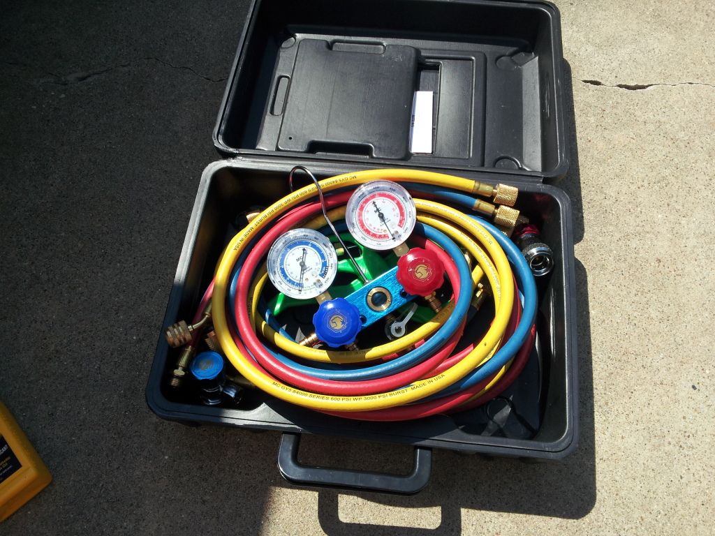
R134a Manifold Gauge Set (This can be had at Harbor Freight for under $100 if you’re on a budget.)
R134a Can Tap
1.5CFM or Greater Vacuum Pump (One that can get below 100 microns. This can also be had at Harbor Freight for under $120 if you’re on a budget.)
17mm Line Wrench
14mm Line Wrench
23mm Line Wrench
27mm Line Wrench
12mm Socket
10mm Socket
12mm Line Wrench
3/8 Ratchet
Extensions
Phillips Screw Driver
Measuring Device (That Displays ml from 0-120ml)
Shop Air (To Push the Flush Fluid through if you have access to this)
In. Lbs. Torque Wrench (You don’t need this just don’t go mega tight on the compressor line and condenser line bolts)
Supplies and New Parts:
ND-8 Compressor Oil (If you do have the capabilities to flush the system completely)
Ester Compressor Oil (If you do not have the capabilities to flush the system completely)
*Optional* Mineral Refrigerant Oil (I use this to lubricate my seals and o-rings.)
OEM Toyota Red A/C O-Rings or Green A/C O-Rings (It is my understanding that the black A/C o-rings do not provide an efficient enough seal, if I am wrong on this feel free to correct me and ill correct it. These only come in 3 different sizes from Toyota; Small, Medium, and Large.)
OEM or Denso Drier (P/N 88471-95401)
*Optional* New Denso Compressor (Not everyone has to do this but it only cost about $260 off Rock Auto so if you want to kill two birds with one stone here the perfect chance to do so.)
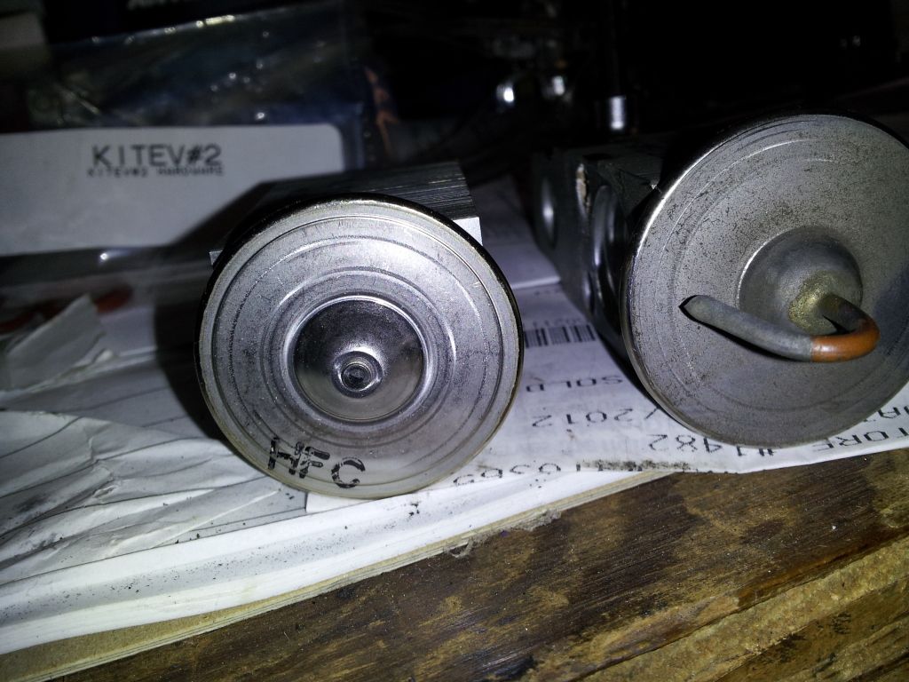
OEM or Denso TXV R134a spe Part # 4750107 (I considered making this optional but there is a difference in the valves in how much refrigerant the HFC valve allows to flow compared to the R12 valve. You don’t have to do this but I HIGHLY recommend do so. I’m not sure if the new valves from Toyota are still R12 or are the R134 valves. The HFC one in the guide was purchased from Rock Auto)
*Optional* Parallel Flow Condenser (Unless you think you’re going to be happy with 60’F vent temps I suggest you get a more efficient Condenser for the less efficient R134 gas.)
Condenser used in this write up can be purchased here. Change year model to application.
http://www.carpartswholesale.com/v5...cpwid=cpwtoyotasupra19881992acip39293p1a/co89
*Optional* Flush Fluid (If you don’t have access to shop air I wouldn’t recommend doing this, just follow the guide using the ester oil instead. It will still work; obviously flushing is going to be the preferred route for people that have access to shop air.)
R134a Adapter fittings (Now on some Supra’s the High Side fitting is smaller and you will need an adapter that can fit it, from my experiences a adapter set for a GM will almost always fit)
R-134a Refrigerant Duh!  Buy 3 Cans, you should only need 2 but the extra can is if you need it.
Now moving onto the guide try and finish this all in one day you don’t want to leave the system open for long, especially on a humid day. Look on the bright side if this brings down your spirits, by the end of the day you should hopefully have cold air blowing from your vents. I will be doing this conversion on Steven89’s 1989 Supra. Before beginning verify the system is empty before opening. If your R134 manifold gauges have standard screw on fittings along with the R134a couplers then you can take the blue line making sure the valves are closed on the manifold. That would be turning them clockwise until they are snug.

If there is any pressure in the system have a shop recover it and pray at the same time it’s the original R12 charge and no some weird blend the previous may have put in. If there is not pressure then go ahead and move on.
Guide to Flushing: To flush first remove the compressor, condenser, drier and thermal expansion valve. This guide is written with the intent that the condenser, drier, and expansion valve will be replaced. Removing the Compressor and expansion valve is just so you don’t get flush fluid in the compressor and so you can flush the evaporator. To flush the lines spray flush fluid in the lines and let it sit for a minute or so and then flush out the garbage that comes out with shop air. It’s recommended that you have a filter for the air, but you can choose to do it without. Just remember to have something to catch the garbage. You don’t want to contaminate other line.
Changing the Compressor Oil:
Step 1: Remove the A/C Belt, or Remove the Serpentine if you have a JZ engine.
Step 2: Remove the Suction and Discharge Lines each have a 12mm bolt holding it down. Hopefully you’ve had the refrigerant recovered by this point because if not be prepared to have refrigerant blasting at your face. Plug the lines with paper towel to prevent any debris getting in while you work.
Step 3: Now 7M guys you have removing the compressor easier than the JZ guys. Remove the four 12mm bolts holding the compressor onto the bracket. JZ guys you have four 14mm bolts and one nut. Then remove the compressor from the car.
Step 4: Get your measuring device and turn the compressor over so the suction and discharge ports are facing down over the measuring cup and turn the compressor clutch to get the oil flowing out. Take note of how much comes out as you will need to add 20ml on top of what comes out. Once you’ve gotten as much oil as you can out of the compressor pour the old oil into a container and wipe your measuring cup clean. Below is how much you should add to the compressor depending on how many components you replace and if you flush.
If you are changing the oil out of the compressor only,
Old Oil Amount + 20ml
If you are changing the oil out of the compressor and replacing the Drier,
Old Oil Amount + 40ml
If you are changing the oil out of the compressor, replacing the Drier, Condenser, and/or replacing the Expansion Valve but not flushing the lines or Evaporator
Old Oil Amount + 80ml – 90ml
If you are changing the oil out of the compressor, replacing the Drier and Condenser, and/or replacing the Expansion Valve and are Flushing the lines and Evaporator,
Old Oil Amount + 120ml – 130ml
Using the guideline above add the amount of suggested amount of oil into the suction port of the compressor. ND-8 if you’re flushing Ester if you aren’t. After you pour the oil in the compressor, turn the compressor by hand clockwise 8-12 revolutions, to get the oil distributed through the compressor.
Step 5: Reinstall compressor it’s the reverse of removal. Remove the wadded towel from the lines and get one Large and one Medium o-ring and lubricate it with compressor oil and install on the appropriate fittings. Install fittings onto the compressor and reinstall your bolts. TSRM says to torque the bolts to 18ft lbs. I used my In. Lbs. Torque Wrench for this if you have one the spec is 216 In. Lbs.
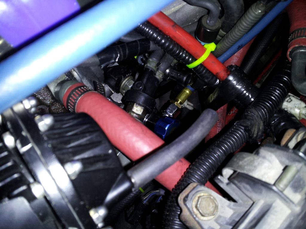
While you are here it’s a good time to install the low side R134a adapter. Do not over tighten these as they WILL break. Replace the valve core with new unit. The one I use in the guide was provided with the kit.


For 7M owners id highly recommend getting a 90 degree low side fitting otherwise you will have a hard time fitting your gauges onto the low side.
Replacing the Condenser: Note that this procedure does requires you to remove the intercooler (before even starting), oil cooler (if you can’t move it out of the way), drier (so I recommend do the condenser replacement the same time you do the drier), and disconnecting most of the lines. You will need; 3 Small O-Rings, 1 Medium O-Ring, and 2 Large O-Rings.
Step 1: Remove the Drier following the guide above.
Step 2: Since we are planning to convert this cars system may as well get the easy part out of the way now. The kit that Steven89 purchased includes the low and high side adapter fittings as well as new valve cores, and Ester oil. I will be adding dye to aid in leak detection should it ever leak.


Start by removing the old valve core from the high side port using a valve core remover, and installing one of the new valve cores.


Next clean the outer threads on the port and take the fitting that the red cap fits on to and screw it onto the fitting snug this down. Do not over tighten in the Toyota TSB retrofit guide they recommend 18ft lbs. If you don’t have a In. Lbs. torque wrench snug it down.

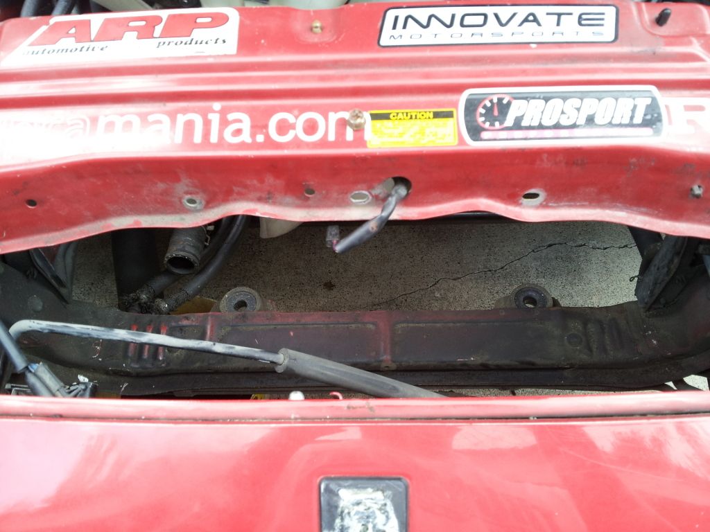
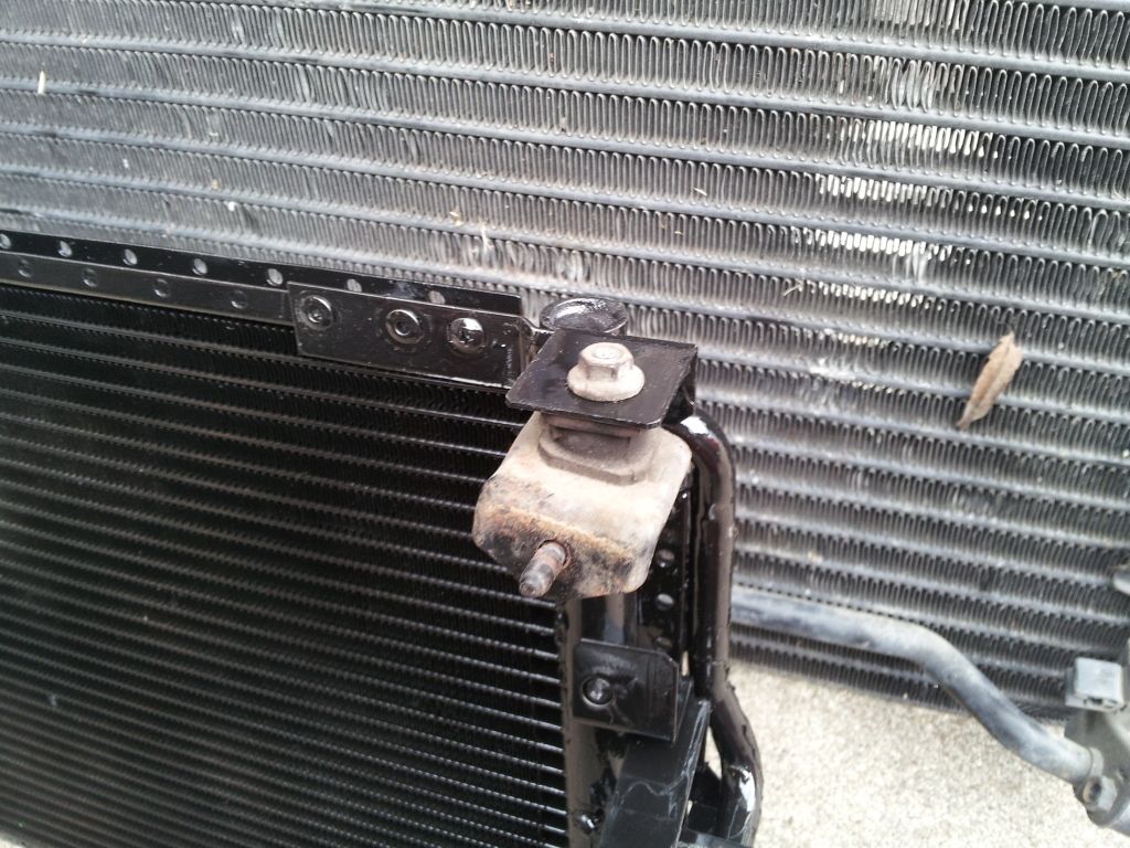
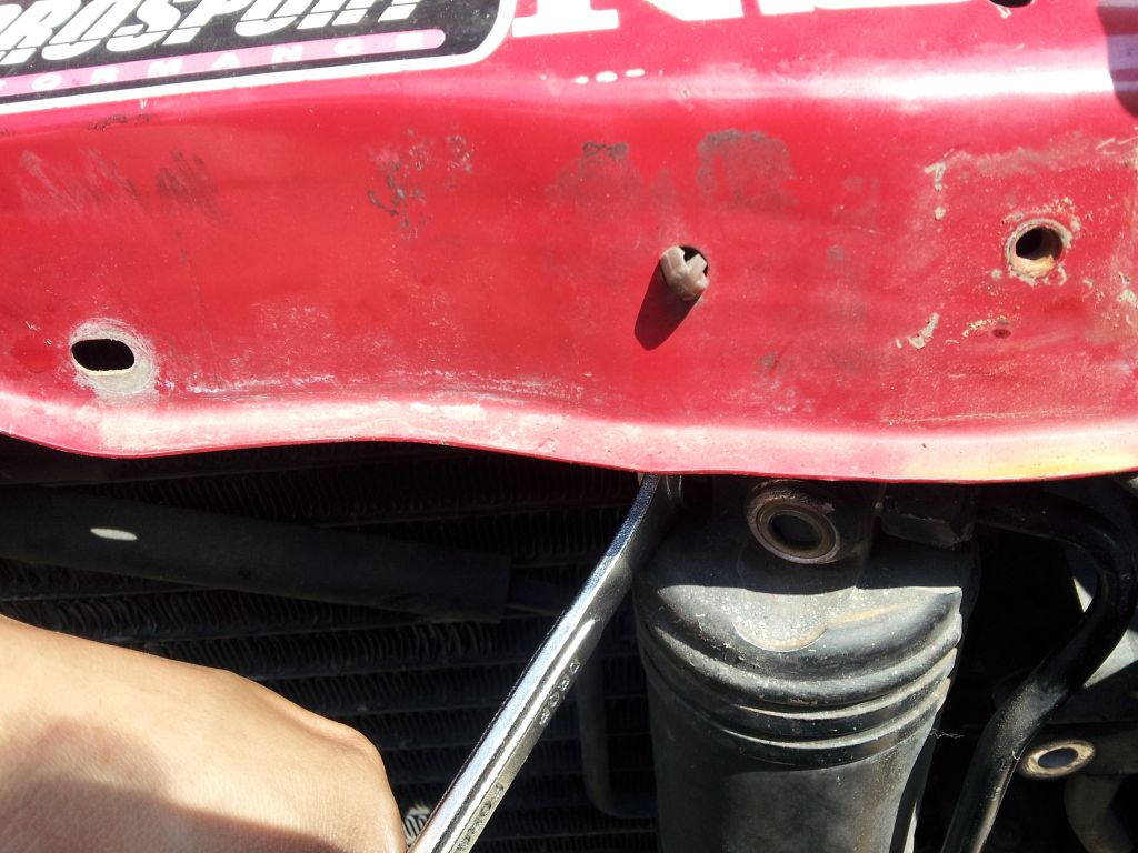
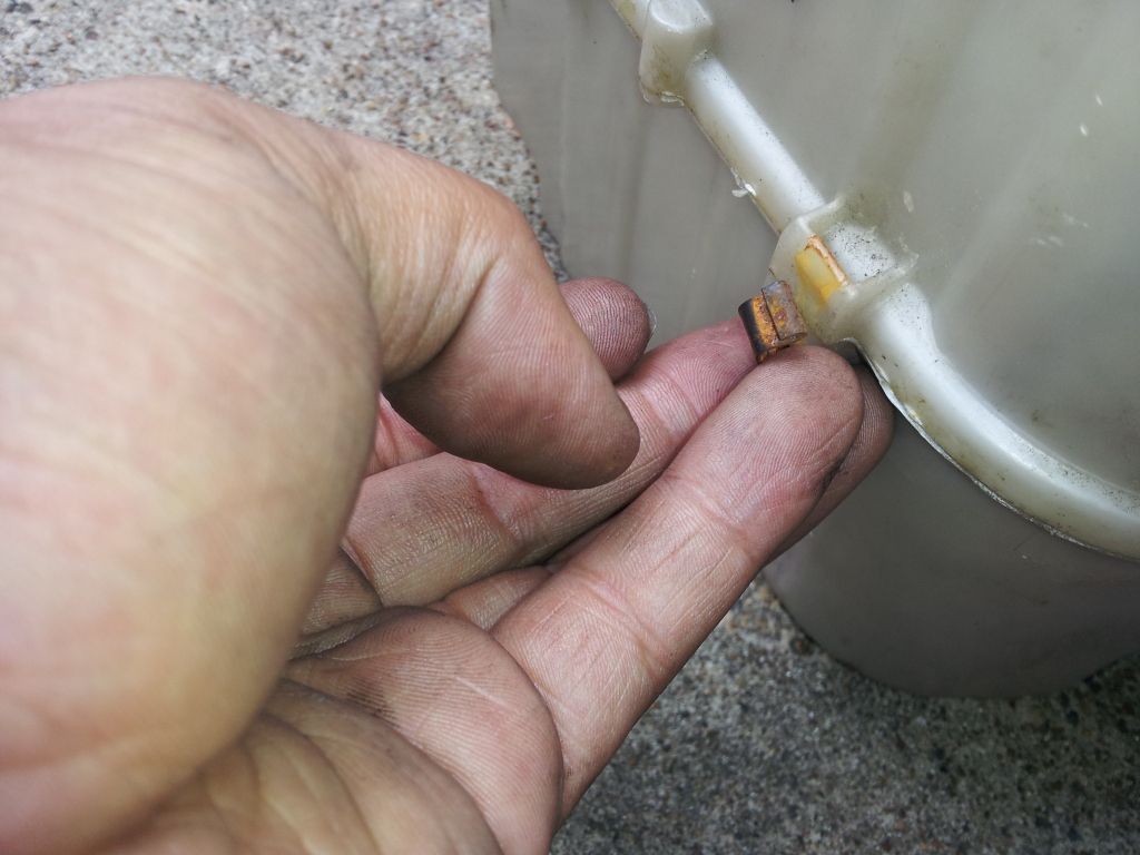
Step 3: Next start undoing the top two Condenser bracket nuts, one is pictured above in the last picture my finger is pointing to it. The other is in the picture below.

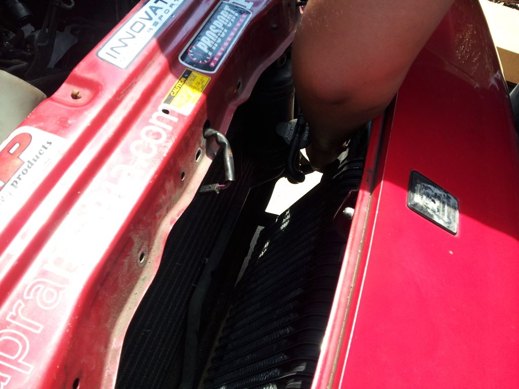
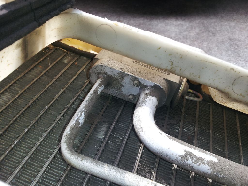
Step 4: Now unbolt the two suction lines pictured below. You can’t see the other line but it’s the one bolted to the condenser on the driver’s side. Don’t forget to plug these lines with something ones you pull them off.
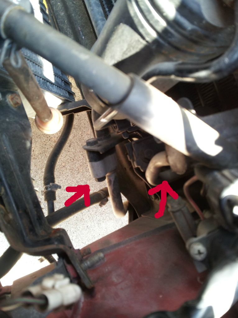
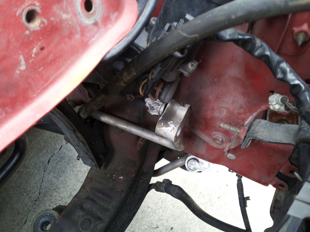
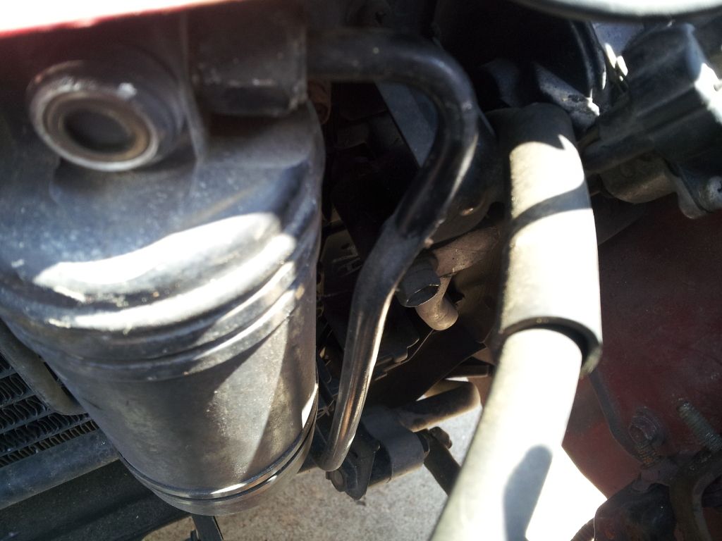
Step 5: Undo the discharge lines one is coming from the condenser, there is one more it’s the arrow on the right. This line goes to the “out” side of the drier so just follow it. Disconnect here at the arrow. You’ll need a 17mm and a 12mm line wrench. Always use a backup wrench on these fittings so you don’t twist the lines. The arrow on the left is another suction line it’s a 10mm bolt undo it like you see Steven89 doing it in the picture. Although this was during reassembly still works. Don’t forget to plug the lines once you remove them.
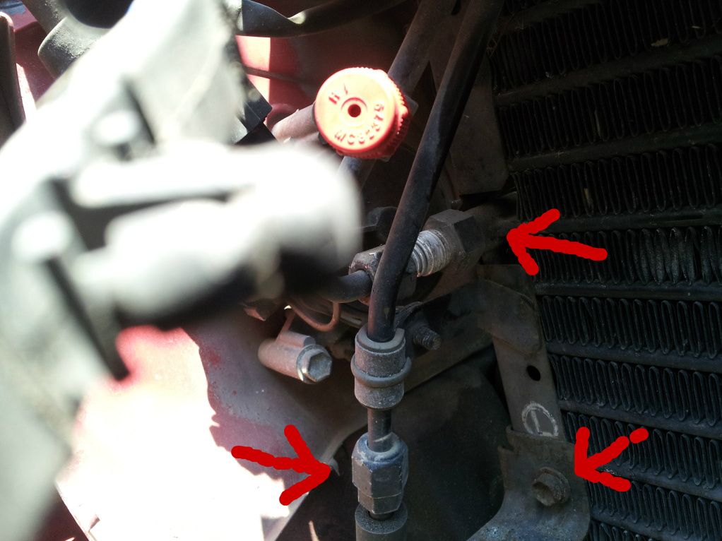
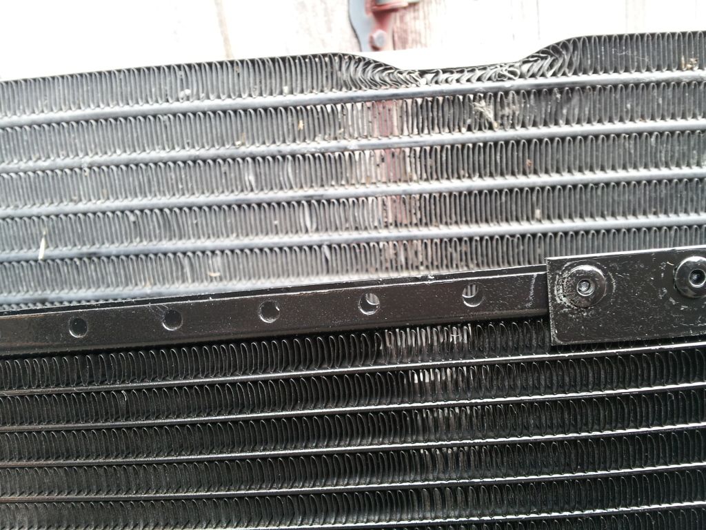
Here is another angle of the two discharge lines that need to be removed. As well as one of the condenser bolts holding the condenser in. There is one more on the driver’s side.
At this point bolt discharge lines unbolted you should be able to just remove them from the vehicle. Set them aside for now if you choose to flush.
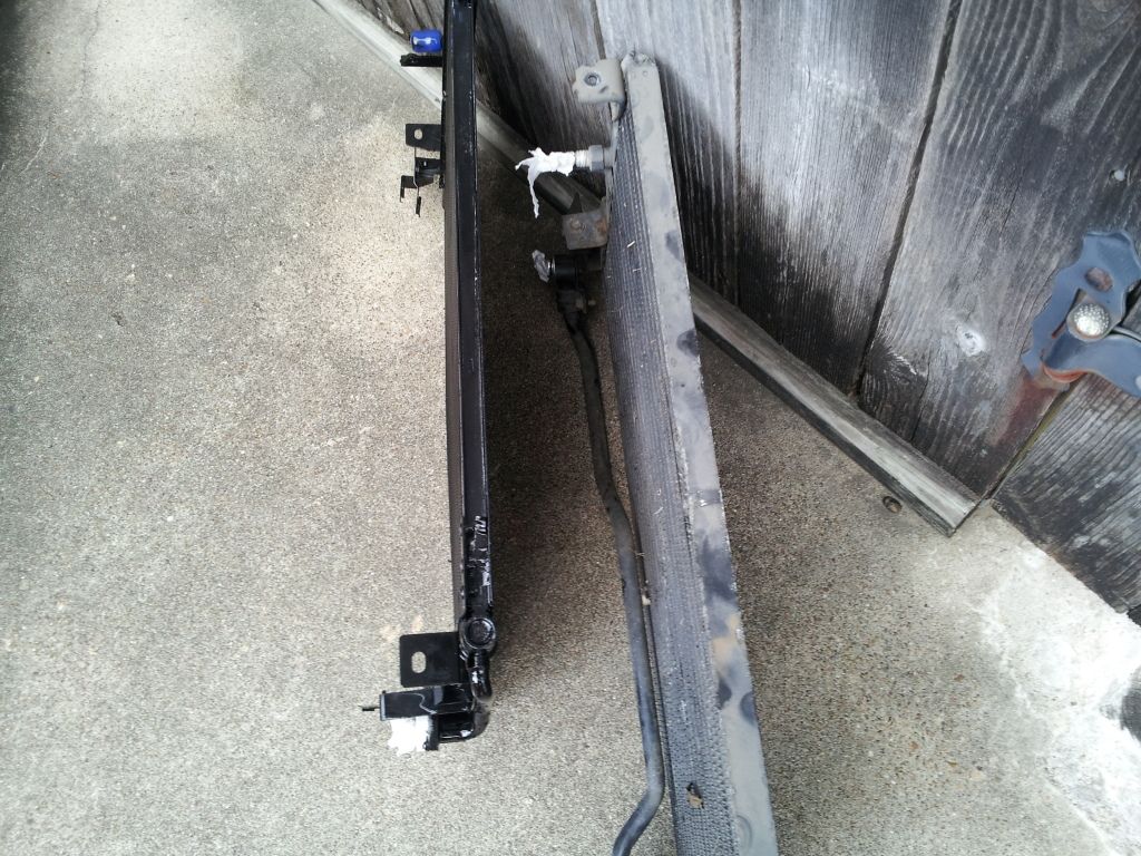
Step 6: Remove the remaining two bolts holding the condenser in place. Now we must gentle wiggle the old condenser out of place. Take your time as you don’t need to bend the hard lines to get this out.
And it’s out
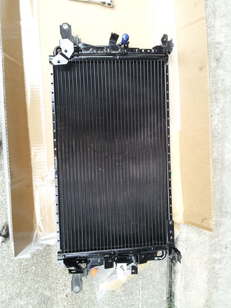
Step 7: Time to remove the new Parallel Flow condenser from the vacuum wrapped packaging. Make sure to keep the ports blocked for now.
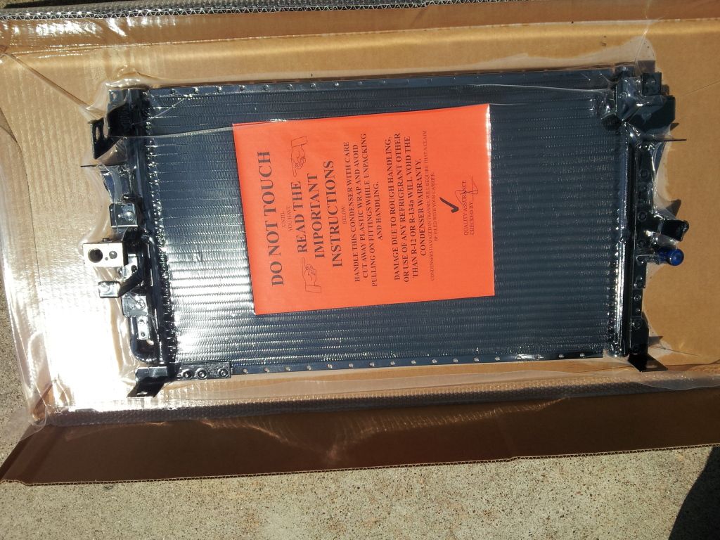
While you get frustrated and how tightly sealed it is has someone else do it and observed how fucked up your old condenser might be.
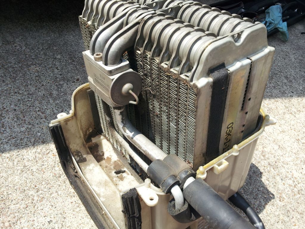
Now let’s see the two condensers side by side.
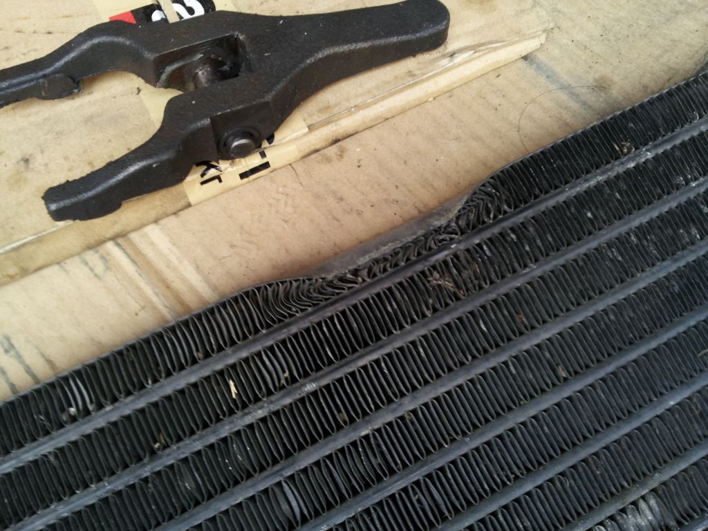
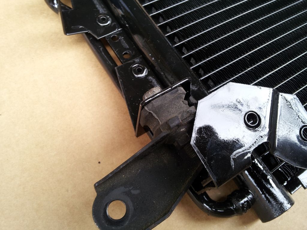
Now if you followed the guide as it was written you should still have a suction tube attached to the old condenser. You will need to transfer this and the top brackets to the new condenser. If you have a pusher fan you will need to trim the lower bracket slightly to get it to fit.
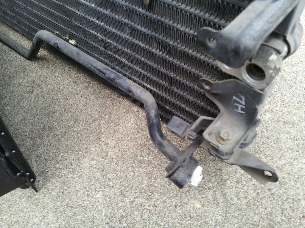
Below is where you would have to trim for the pusher fan. Steven89’s car did not have one so we aren’t sure to what extent but it shouldn’t be too hard to figure out.
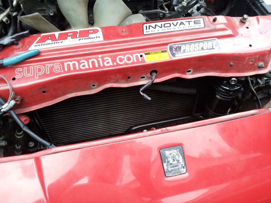
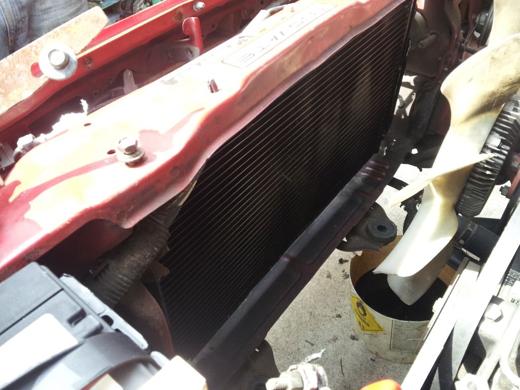
Step 8: Wiggle the new condenser into place this time it’ll be easier as the new condenser is slightly smaller height wise. Bolt the condenser into place with the two bolts and two nuts. Get your new o-rings oil and installed. Reverse of disassembly tighten the bolts to TSRM spec found on this page. http://www.cygnusx1.net/Supra/Library/TSRM/MK3/manual.aspx?S=AC&P=29
Step 9: Install new drier following the guide for Drier Replacement posted below.
Step 10: Stand back and look at your hard work and cut up knuckles.
Brought to you by
If you need extra help with this here is the link to the TSRM http://www.cygnusx1.net/Supra/Library/TSRM/MK3/manual.aspx?S=AC&P=29
Replacing the Receiver Drier:
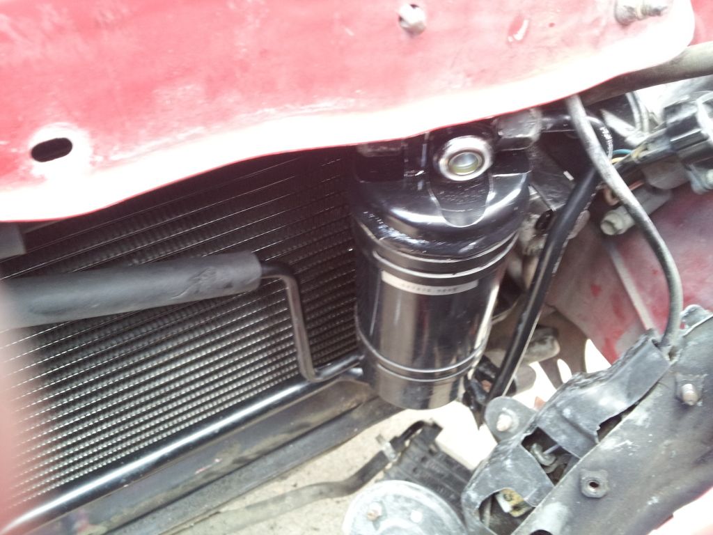
Step 1: Remove the Overflow Bottle and Bracket. To remove the bottle just pull straight up from the bottom and disconnect the plug at the bottom. Then remove the two bolts holding the overflow bracket on.
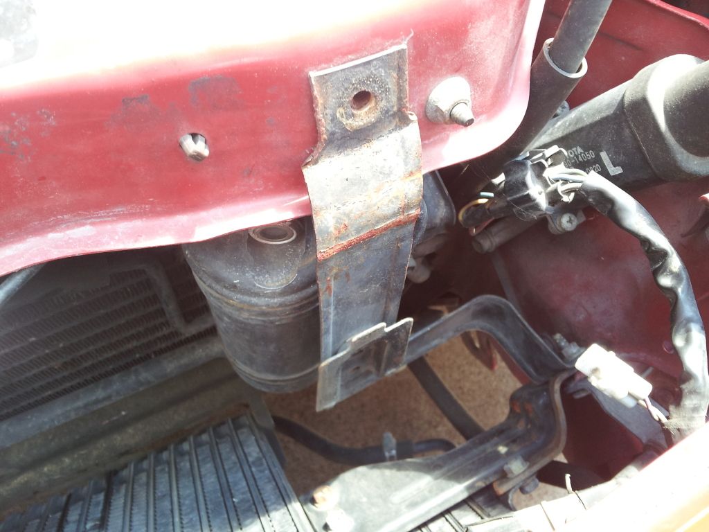
Step 2: With the bracket removed grab the 17mm line wrench and break the two lines connected to the drier loose. They aren’t on tight and shouldn’t be, so getting them loose should be real easy. Once they are loose, grab a 10mm socket and unscrew the two bolts holding each bracket onto the drier off. Don’t forget to plug the lines once you remove them.
Step 3: Now Position your new drier into the brackets and enjoy the time you’re going to have to contemplate how the hell you ever managed to get it off and how you plan to get it back on. However no matter how angry you get while doing this remember to not take off the cap fittings on the new drier until you are 100% sure you’re ready to install them back on the lines. Now when you manage to get the bracket bolts started back into the thread do not tighten then yet you need room to turn the drier to the correct position. You will need two small o rings for this make sure to lubricate them, and install the new ones on.
Step 4: Now you’re ready to reinstall the lines, remove the cap fittings and start threading them on. Once they are on snug finger tight, now you can snug down the bracket bolts. After that take your 17mm line wrench and snug them down with the wrench. Remember these are only tightening to 4ft lbs. Yes so don’t go Hercules on these.
If you need Extra Help here is the link from the TSRM http://www.cygnusx1.net/Supra/Library/TSRM/MK3/manual.aspx?Section=AC&P=28
Replacing the Thermal Expansion Valve:
Step 1: Remove Glovebox, Remove Lower Glovebox Panel, Remove ECU, and ABS Computer.
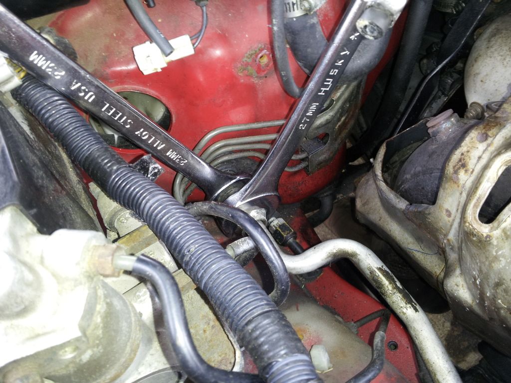
Step 2: Using two wrenches (one acts as a backup wrench), Loosen the suction line you'll need a 23mm and a 27mm wrench. Loosen the discharge line you'll need a 14mm and a 17mm Remove the Four Bolts and Three Nuts holding the Evaporator box to the vehicle. Remember plug the lines you disconnect. Youll need one large O-ring and one small O-ring.
http://www.cygnusx1.net/Supra/Library/TSRM/MK3/manual.aspx?S=AC&P=33
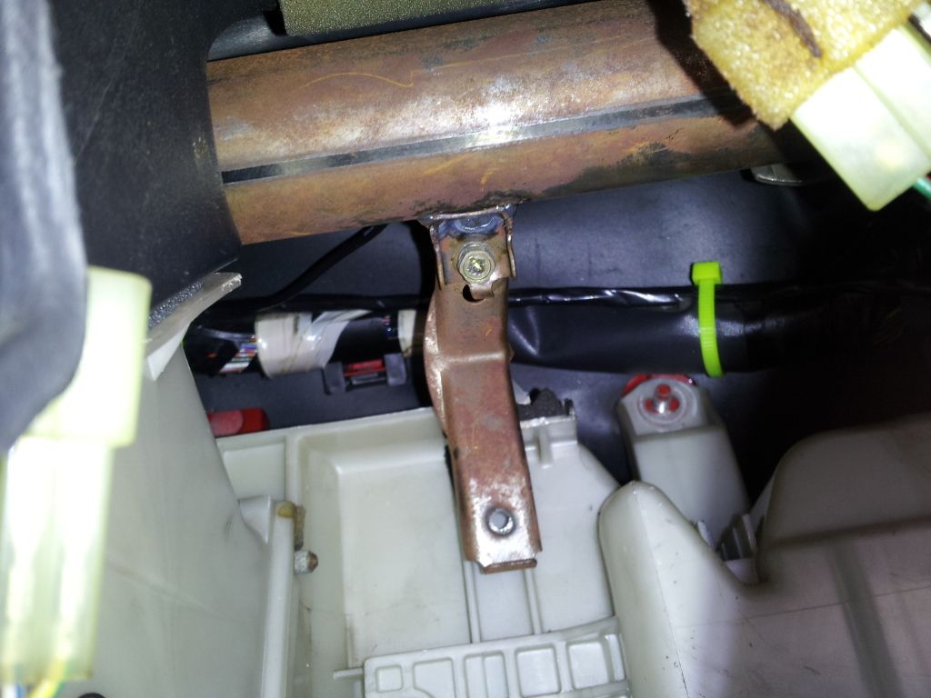
*TIP* You may have to remove the small bracket above that holds the ECU in place in order to pull the Evaporator out.
Step 3: Unscrew the four screws, and pop the three clips holding the evaporator box together.
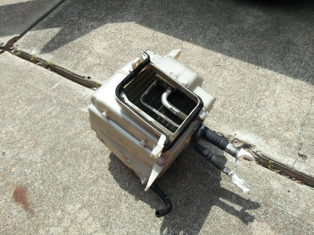
This is our target
Step 4: Pull the case apart pull the thermister from inside the evaporator fins, take the evaporator to a work bench.
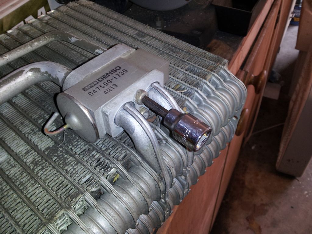
Step 5: Your Expansion valve setup might look different depending on the year but in this case for a 88 and 89 you'll need a 6mm allen to unbolt the expansion valve.
Side by side
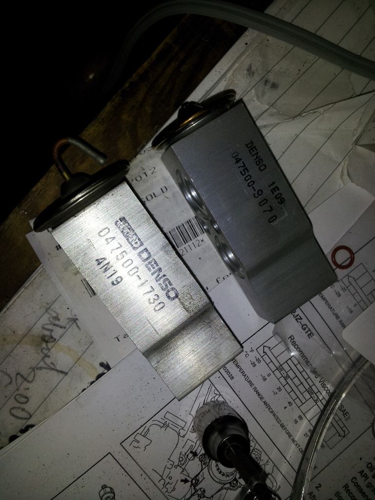
You'll need three large o-rings and one small o-rings.
Step 6: Reinstallation is the reverse of the disassembly. Do not over torque these allen bolts and lines. The Allen bolts is 10 ft lbs and the lines are 14-18ft lbs. So do not over crank these and remember use a back up wrench.
Charging the R-134a: ***I will post pics for this as i finish the guide and as i go***
***section still incomplete***
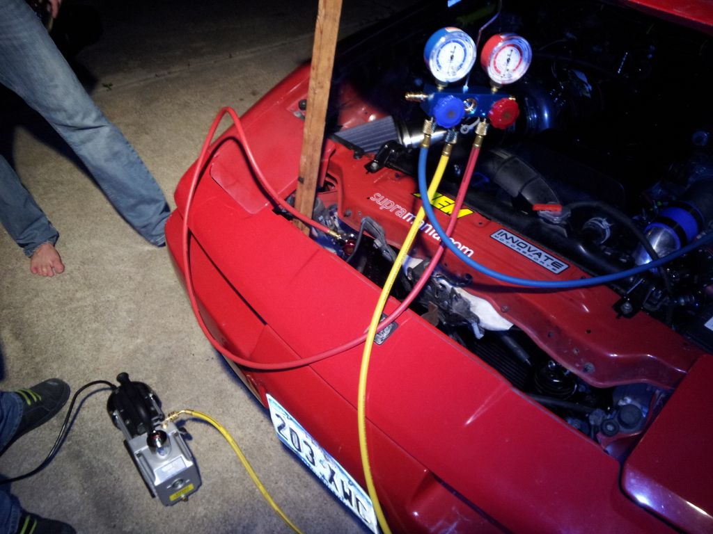
Step 1: Start by bringing out your manifold gauges and hooking them up to the low and high side. If your retrofit kit came with color coordinated caps then match the hose color to the caps. Blue for Low, and Red for High. Now depending on your gauge setup your manifold adapters may be a screw type like mine so you’ll need to screw the top of the adapters down in order to depress the valve.
Step 2: Now hook up the yellow hose or “charge line” to the vacuum pump. Switch the pump on and open bolt the low and high side valves on the manifold. Make sure you are able to pull a vacuum below 29inhg if you can’t stop the pump you have a leak somewhere. If you are pulling a strong good vacuum continue to do so for an hour to an hour and a half.
Step 3: After your vacuum period has ended close the low and high side valves on the manifold and shut the pump off. Now let the car sit for 30min to an hour. Some even let their cars sit overnight. The point of this is seeing how much vacuum you lose. The faster you lose vacuum i.e. 10min you’re already losing vacuum you have a leak that needs to found and addressed before continuing. If after your leak test time no vacuum is lost continue to the next step.
Step 4: Disconnect the charge hose from the pump. If you want to charge by weight you’ll need to weigh an empty can with a can tap and set that as your tare weight. Next screw on your tap onto the can or R134a making sure the pin is unscrewed all the way.
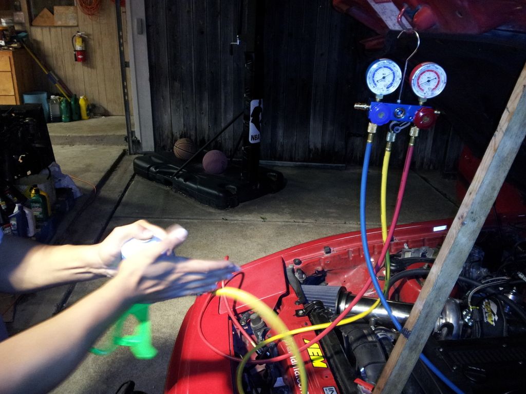
Step 5: Attach the charge line to the tap and screw the pin to puncture the can. Once punctured fully unscrew the pin and turn the can upside down. While holding the can upside down follow the charge line up to the manifold where it screws on and unscrew the line at the manifold until it hisses or in this case you see liquid refrigerant purge from the line. This is to bleed the line. You must do this every can to avoid outside air contamination. Once it’s bled, you can weigh (if charging by weight) your can again to know how much you will be putting in with the first can.
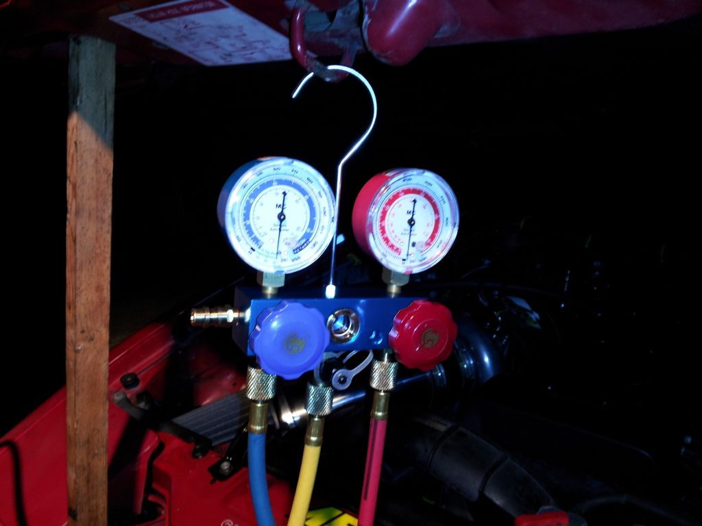
Step 6: Now onto charging, make sure the car is turned off for this first part. Take your can and hold it upside down, and open the high side valve on the manifold. If your gauges have a sight glass on the manifold then you should see liquid refrigerant in the side glass being drawn in. The vacuum in the system should be sufficient enough to draw the entire first can in. At this point you should see the gauges start moving up this is normal. Shake the can and rub the can to create heat so you get it all in.
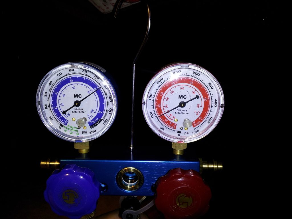
This is Static pressure after the first can has been emptied into the system as you can see both gauges are showing the same reading, meaning there is enough liquid refrigerant in the system.
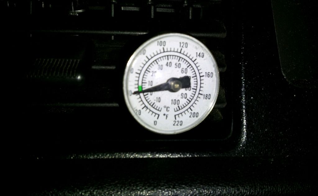
Step 7: Once the entire first can has been discharge into the system you can weigh the can to verify or close the high side valve and open the charge line as see if there is anymore refrigerant in it. Once the can is empty make sure the high side valve is closed, unscrew your R134 can from the tap and screw on a new full can. This time we will charge gas. The point of charging liquid first is its less work, makes charging faster, and the liquid will help distribute the oil faster. Follow the same procedure for tapping the can and bleeding the charge line. Now start the car and turn the A/C on max cold blower speed at Medium or High and recirculate on. Open the low side valve on the manifold and set your can on the scale. Also you can speed up the charge process by dipping your can into a pot of warm water to increase the internal pressure. Toyota says for a retrofit to charge 650g or 22.928oz or 1.43lbs of R-134a. So it should almost take the entire of the second can. Don’t worry if you go over a little the general rule is 80-90% of the original R-12 charge. It will be hard to judge the charge using the sight glass method as its normal to see a few bubbles when using R-134a. While charging spray water over the condenser, and monitor your vent temps with a thermometer. It should be 30’F less (proper charge and working) than what the ambient temp is measured 8in from the condenser.
*Update*
Ive uploaded the original Toyota TSB for the conversion.
View attachment Toyota TSB R12-134.pdf
This DIY guide is to help those who wish to convert their working but leaking or non working A/C systems on the MK3 Supra from R-12 to R-134a. First below are a list of tools, new parts, and supplies you’ll need in order to follow this guide.
Tools:
R134a Manifold Gauge Set (This can be had at Harbor Freight for under $100 if you’re on a budget.)
R134a Can Tap
1.5CFM or Greater Vacuum Pump (One that can get below 100 microns. This can also be had at Harbor Freight for under $120 if you’re on a budget.)
17mm Line Wrench
14mm Line Wrench
23mm Line Wrench
27mm Line Wrench
12mm Socket
10mm Socket
12mm Line Wrench
3/8 Ratchet
Extensions
Phillips Screw Driver
Measuring Device (That Displays ml from 0-120ml)
Shop Air (To Push the Flush Fluid through if you have access to this)
In. Lbs. Torque Wrench (You don’t need this just don’t go mega tight on the compressor line and condenser line bolts)
Supplies and New Parts:
ND-8 Compressor Oil (If you do have the capabilities to flush the system completely)
Ester Compressor Oil (If you do not have the capabilities to flush the system completely)
*Optional* Mineral Refrigerant Oil (I use this to lubricate my seals and o-rings.)
OEM Toyota Red A/C O-Rings or Green A/C O-Rings (It is my understanding that the black A/C o-rings do not provide an efficient enough seal, if I am wrong on this feel free to correct me and ill correct it. These only come in 3 different sizes from Toyota; Small, Medium, and Large.)
OEM or Denso Drier (P/N 88471-95401)
*Optional* New Denso Compressor (Not everyone has to do this but it only cost about $260 off Rock Auto so if you want to kill two birds with one stone here the perfect chance to do so.)
OEM or Denso TXV R134a spe Part # 4750107 (I considered making this optional but there is a difference in the valves in how much refrigerant the HFC valve allows to flow compared to the R12 valve. You don’t have to do this but I HIGHLY recommend do so. I’m not sure if the new valves from Toyota are still R12 or are the R134 valves. The HFC one in the guide was purchased from Rock Auto)
*Optional* Parallel Flow Condenser (Unless you think you’re going to be happy with 60’F vent temps I suggest you get a more efficient Condenser for the less efficient R134 gas.)
Condenser used in this write up can be purchased here. Change year model to application.
http://www.carpartswholesale.com/v5...cpwid=cpwtoyotasupra19881992acip39293p1a/co89
*Optional* Flush Fluid (If you don’t have access to shop air I wouldn’t recommend doing this, just follow the guide using the ester oil instead. It will still work; obviously flushing is going to be the preferred route for people that have access to shop air.)
R134a Adapter fittings (Now on some Supra’s the High Side fitting is smaller and you will need an adapter that can fit it, from my experiences a adapter set for a GM will almost always fit)
R-134a Refrigerant Duh!  Buy 3 Cans, you should only need 2 but the extra can is if you need it.
Now moving onto the guide try and finish this all in one day you don’t want to leave the system open for long, especially on a humid day. Look on the bright side if this brings down your spirits, by the end of the day you should hopefully have cold air blowing from your vents. I will be doing this conversion on Steven89’s 1989 Supra. Before beginning verify the system is empty before opening. If your R134 manifold gauges have standard screw on fittings along with the R134a couplers then you can take the blue line making sure the valves are closed on the manifold. That would be turning them clockwise until they are snug.
If there is any pressure in the system have a shop recover it and pray at the same time it’s the original R12 charge and no some weird blend the previous may have put in. If there is not pressure then go ahead and move on.
Guide to Flushing: To flush first remove the compressor, condenser, drier and thermal expansion valve. This guide is written with the intent that the condenser, drier, and expansion valve will be replaced. Removing the Compressor and expansion valve is just so you don’t get flush fluid in the compressor and so you can flush the evaporator. To flush the lines spray flush fluid in the lines and let it sit for a minute or so and then flush out the garbage that comes out with shop air. It’s recommended that you have a filter for the air, but you can choose to do it without. Just remember to have something to catch the garbage. You don’t want to contaminate other line.
Changing the Compressor Oil:
Step 1: Remove the A/C Belt, or Remove the Serpentine if you have a JZ engine.
Step 2: Remove the Suction and Discharge Lines each have a 12mm bolt holding it down. Hopefully you’ve had the refrigerant recovered by this point because if not be prepared to have refrigerant blasting at your face. Plug the lines with paper towel to prevent any debris getting in while you work.
Step 3: Now 7M guys you have removing the compressor easier than the JZ guys. Remove the four 12mm bolts holding the compressor onto the bracket. JZ guys you have four 14mm bolts and one nut. Then remove the compressor from the car.
Step 4: Get your measuring device and turn the compressor over so the suction and discharge ports are facing down over the measuring cup and turn the compressor clutch to get the oil flowing out. Take note of how much comes out as you will need to add 20ml on top of what comes out. Once you’ve gotten as much oil as you can out of the compressor pour the old oil into a container and wipe your measuring cup clean. Below is how much you should add to the compressor depending on how many components you replace and if you flush.
If you are changing the oil out of the compressor only,
Old Oil Amount + 20ml
If you are changing the oil out of the compressor and replacing the Drier,
Old Oil Amount + 40ml
If you are changing the oil out of the compressor, replacing the Drier, Condenser, and/or replacing the Expansion Valve but not flushing the lines or Evaporator
Old Oil Amount + 80ml – 90ml
If you are changing the oil out of the compressor, replacing the Drier and Condenser, and/or replacing the Expansion Valve and are Flushing the lines and Evaporator,
Old Oil Amount + 120ml – 130ml
Using the guideline above add the amount of suggested amount of oil into the suction port of the compressor. ND-8 if you’re flushing Ester if you aren’t. After you pour the oil in the compressor, turn the compressor by hand clockwise 8-12 revolutions, to get the oil distributed through the compressor.
Step 5: Reinstall compressor it’s the reverse of removal. Remove the wadded towel from the lines and get one Large and one Medium o-ring and lubricate it with compressor oil and install on the appropriate fittings. Install fittings onto the compressor and reinstall your bolts. TSRM says to torque the bolts to 18ft lbs. I used my In. Lbs. Torque Wrench for this if you have one the spec is 216 In. Lbs.
While you are here it’s a good time to install the low side R134a adapter. Do not over tighten these as they WILL break. Replace the valve core with new unit. The one I use in the guide was provided with the kit.
For 7M owners id highly recommend getting a 90 degree low side fitting otherwise you will have a hard time fitting your gauges onto the low side.
Replacing the Condenser: Note that this procedure does requires you to remove the intercooler (before even starting), oil cooler (if you can’t move it out of the way), drier (so I recommend do the condenser replacement the same time you do the drier), and disconnecting most of the lines. You will need; 3 Small O-Rings, 1 Medium O-Ring, and 2 Large O-Rings.
Step 1: Remove the Drier following the guide above.
Step 2: Since we are planning to convert this cars system may as well get the easy part out of the way now. The kit that Steven89 purchased includes the low and high side adapter fittings as well as new valve cores, and Ester oil. I will be adding dye to aid in leak detection should it ever leak.
Start by removing the old valve core from the high side port using a valve core remover, and installing one of the new valve cores.
Next clean the outer threads on the port and take the fitting that the red cap fits on to and screw it onto the fitting snug this down. Do not over tighten in the Toyota TSB retrofit guide they recommend 18ft lbs. If you don’t have a In. Lbs. torque wrench snug it down.
Step 3: Next start undoing the top two Condenser bracket nuts, one is pictured above in the last picture my finger is pointing to it. The other is in the picture below.
Step 4: Now unbolt the two suction lines pictured below. You can’t see the other line but it’s the one bolted to the condenser on the driver’s side. Don’t forget to plug these lines with something ones you pull them off.
Step 5: Undo the discharge lines one is coming from the condenser, there is one more it’s the arrow on the right. This line goes to the “out” side of the drier so just follow it. Disconnect here at the arrow. You’ll need a 17mm and a 12mm line wrench. Always use a backup wrench on these fittings so you don’t twist the lines. The arrow on the left is another suction line it’s a 10mm bolt undo it like you see Steven89 doing it in the picture. Although this was during reassembly still works. Don’t forget to plug the lines once you remove them.
Here is another angle of the two discharge lines that need to be removed. As well as one of the condenser bolts holding the condenser in. There is one more on the driver’s side.
At this point bolt discharge lines unbolted you should be able to just remove them from the vehicle. Set them aside for now if you choose to flush.
Step 6: Remove the remaining two bolts holding the condenser in place. Now we must gentle wiggle the old condenser out of place. Take your time as you don’t need to bend the hard lines to get this out.
And it’s out
Step 7: Time to remove the new Parallel Flow condenser from the vacuum wrapped packaging. Make sure to keep the ports blocked for now.
While you get frustrated and how tightly sealed it is has someone else do it and observed how fucked up your old condenser might be.
Now let’s see the two condensers side by side.
Now if you followed the guide as it was written you should still have a suction tube attached to the old condenser. You will need to transfer this and the top brackets to the new condenser. If you have a pusher fan you will need to trim the lower bracket slightly to get it to fit.
Below is where you would have to trim for the pusher fan. Steven89’s car did not have one so we aren’t sure to what extent but it shouldn’t be too hard to figure out.
Step 8: Wiggle the new condenser into place this time it’ll be easier as the new condenser is slightly smaller height wise. Bolt the condenser into place with the two bolts and two nuts. Get your new o-rings oil and installed. Reverse of disassembly tighten the bolts to TSRM spec found on this page. http://www.cygnusx1.net/Supra/Library/TSRM/MK3/manual.aspx?S=AC&P=29
Step 9: Install new drier following the guide for Drier Replacement posted below.
Step 10: Stand back and look at your hard work and cut up knuckles.
Brought to you by
If you need extra help with this here is the link to the TSRM http://www.cygnusx1.net/Supra/Library/TSRM/MK3/manual.aspx?S=AC&P=29
Replacing the Receiver Drier:
Step 1: Remove the Overflow Bottle and Bracket. To remove the bottle just pull straight up from the bottom and disconnect the plug at the bottom. Then remove the two bolts holding the overflow bracket on.
Step 2: With the bracket removed grab the 17mm line wrench and break the two lines connected to the drier loose. They aren’t on tight and shouldn’t be, so getting them loose should be real easy. Once they are loose, grab a 10mm socket and unscrew the two bolts holding each bracket onto the drier off. Don’t forget to plug the lines once you remove them.
Step 3: Now Position your new drier into the brackets and enjoy the time you’re going to have to contemplate how the hell you ever managed to get it off and how you plan to get it back on. However no matter how angry you get while doing this remember to not take off the cap fittings on the new drier until you are 100% sure you’re ready to install them back on the lines. Now when you manage to get the bracket bolts started back into the thread do not tighten then yet you need room to turn the drier to the correct position. You will need two small o rings for this make sure to lubricate them, and install the new ones on.
Step 4: Now you’re ready to reinstall the lines, remove the cap fittings and start threading them on. Once they are on snug finger tight, now you can snug down the bracket bolts. After that take your 17mm line wrench and snug them down with the wrench. Remember these are only tightening to 4ft lbs. Yes so don’t go Hercules on these.
If you need Extra Help here is the link from the TSRM http://www.cygnusx1.net/Supra/Library/TSRM/MK3/manual.aspx?Section=AC&P=28
Replacing the Thermal Expansion Valve:
Step 1: Remove Glovebox, Remove Lower Glovebox Panel, Remove ECU, and ABS Computer.
Step 2: Using two wrenches (one acts as a backup wrench), Loosen the suction line you'll need a 23mm and a 27mm wrench. Loosen the discharge line you'll need a 14mm and a 17mm Remove the Four Bolts and Three Nuts holding the Evaporator box to the vehicle. Remember plug the lines you disconnect. Youll need one large O-ring and one small O-ring.
http://www.cygnusx1.net/Supra/Library/TSRM/MK3/manual.aspx?S=AC&P=33
*TIP* You may have to remove the small bracket above that holds the ECU in place in order to pull the Evaporator out.
Step 3: Unscrew the four screws, and pop the three clips holding the evaporator box together.
This is our target
Step 4: Pull the case apart pull the thermister from inside the evaporator fins, take the evaporator to a work bench.
Step 5: Your Expansion valve setup might look different depending on the year but in this case for a 88 and 89 you'll need a 6mm allen to unbolt the expansion valve.
Side by side
You'll need three large o-rings and one small o-rings.
Step 6: Reinstallation is the reverse of the disassembly. Do not over torque these allen bolts and lines. The Allen bolts is 10 ft lbs and the lines are 14-18ft lbs. So do not over crank these and remember use a back up wrench.
Charging the R-134a: ***I will post pics for this as i finish the guide and as i go***
***section still incomplete***
Step 1: Start by bringing out your manifold gauges and hooking them up to the low and high side. If your retrofit kit came with color coordinated caps then match the hose color to the caps. Blue for Low, and Red for High. Now depending on your gauge setup your manifold adapters may be a screw type like mine so you’ll need to screw the top of the adapters down in order to depress the valve.
Step 2: Now hook up the yellow hose or “charge line” to the vacuum pump. Switch the pump on and open bolt the low and high side valves on the manifold. Make sure you are able to pull a vacuum below 29inhg if you can’t stop the pump you have a leak somewhere. If you are pulling a strong good vacuum continue to do so for an hour to an hour and a half.
Step 3: After your vacuum period has ended close the low and high side valves on the manifold and shut the pump off. Now let the car sit for 30min to an hour. Some even let their cars sit overnight. The point of this is seeing how much vacuum you lose. The faster you lose vacuum i.e. 10min you’re already losing vacuum you have a leak that needs to found and addressed before continuing. If after your leak test time no vacuum is lost continue to the next step.
Step 4: Disconnect the charge hose from the pump. If you want to charge by weight you’ll need to weigh an empty can with a can tap and set that as your tare weight. Next screw on your tap onto the can or R134a making sure the pin is unscrewed all the way.
Step 5: Attach the charge line to the tap and screw the pin to puncture the can. Once punctured fully unscrew the pin and turn the can upside down. While holding the can upside down follow the charge line up to the manifold where it screws on and unscrew the line at the manifold until it hisses or in this case you see liquid refrigerant purge from the line. This is to bleed the line. You must do this every can to avoid outside air contamination. Once it’s bled, you can weigh (if charging by weight) your can again to know how much you will be putting in with the first can.
Step 6: Now onto charging, make sure the car is turned off for this first part. Take your can and hold it upside down, and open the high side valve on the manifold. If your gauges have a sight glass on the manifold then you should see liquid refrigerant in the side glass being drawn in. The vacuum in the system should be sufficient enough to draw the entire first can in. At this point you should see the gauges start moving up this is normal. Shake the can and rub the can to create heat so you get it all in.
This is Static pressure after the first can has been emptied into the system as you can see both gauges are showing the same reading, meaning there is enough liquid refrigerant in the system.
Step 7: Once the entire first can has been discharge into the system you can weigh the can to verify or close the high side valve and open the charge line as see if there is anymore refrigerant in it. Once the can is empty make sure the high side valve is closed, unscrew your R134 can from the tap and screw on a new full can. This time we will charge gas. The point of charging liquid first is its less work, makes charging faster, and the liquid will help distribute the oil faster. Follow the same procedure for tapping the can and bleeding the charge line. Now start the car and turn the A/C on max cold blower speed at Medium or High and recirculate on. Open the low side valve on the manifold and set your can on the scale. Also you can speed up the charge process by dipping your can into a pot of warm water to increase the internal pressure. Toyota says for a retrofit to charge 650g or 22.928oz or 1.43lbs of R-134a. So it should almost take the entire of the second can. Don’t worry if you go over a little the general rule is 80-90% of the original R-12 charge. It will be hard to judge the charge using the sight glass method as its normal to see a few bubbles when using R-134a. While charging spray water over the condenser, and monitor your vent temps with a thermometer. It should be 30’F less (proper charge and working) than what the ambient temp is measured 8in from the condenser.
*Update*
Ive uploaded the original Toyota TSB for the conversion.
View attachment Toyota TSB R12-134.pdf
Last edited:
")