
So would you say the boost controller is a better bang for the buck than the exhaust? I cant wait to see how well your led lighting turns out.
The Fruition of Obsession -- 310,000 mile makeover --
- Thread starter suprarx7nut
- Start date
You are using an out of date browser. It may not display this or other websites correctly.
You should upgrade or use an alternative browser.
You should upgrade or use an alternative browser.
Well they kinda go hand and hand. Without the exhaust, the boost controller will show you the limitations of the stock exhaust fast.
I'd say the exhaust should definitely come first.") and raptor racing makes an exceptional product!
and raptor racing makes an exceptional product!
A downpipe/elbow is crucial. I love my divorced downpipe from raptor racing. Excellent quality, seals perfectly.
Sent from my ADR6400L using Tapatalk
I'd say the exhaust should definitely come first.
and raptor racing makes an exceptional product!A downpipe/elbow is crucial. I love my divorced downpipe from raptor racing. Excellent quality, seals perfectly.
Sent from my ADR6400L using Tapatalk
Mini-update. I guess more of a timestamp just to give myself something to look back at.
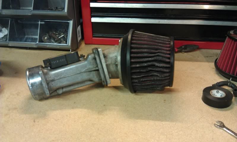
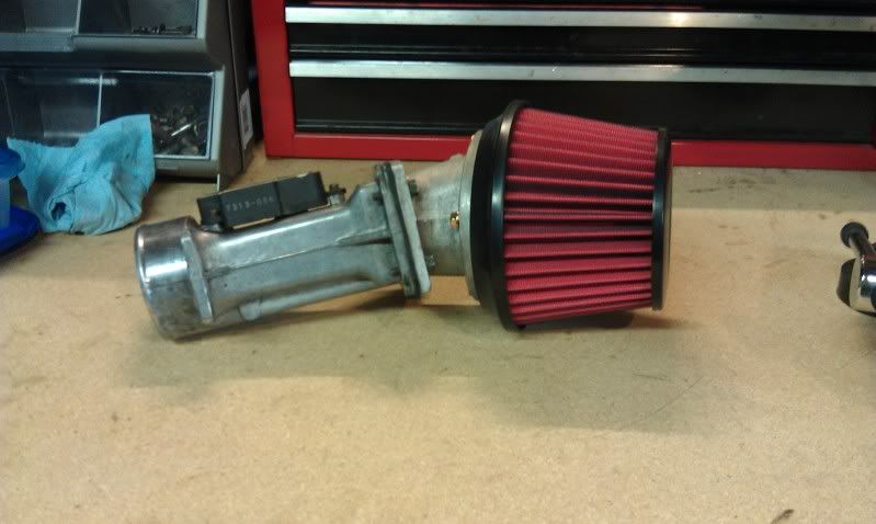
Got a new, very, very overdue air filter today from Apexi.
Old:
New:
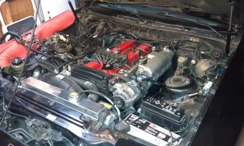
Engine bay as it stands now. Power Steering will be moved this winter. I'd like to move the accessories on the sides as well. Also relocate the charcoal canister perhaps. I may as well move the cruise control too since I can't use it with my homemade throttle bracket.
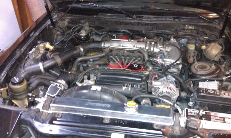
It's dirty, messy, and nowhere near where i want it, but I'm making slow progress.
Got a new, very, very overdue air filter today from Apexi.
Old:
New:
Engine bay as it stands now. Power Steering will be moved this winter. I'd like to move the accessories on the sides as well. Also relocate the charcoal canister perhaps. I may as well move the cruise control too since I can't use it with my homemade throttle bracket.
It's dirty, messy, and nowhere near where i want it, but I'm making slow progress.
CyFi6;1766950 said:Lookin good keep it up! Pics of the new gauge lighting?
Yeah, I'm being lazy. I got the actual boards made for each gauge, just need to install them in the actual dash. Right now everything is still installed in the demo dash. SHould take just one solid night of work, but I haven't found the time.
JetBlackNewYear;1767158 said:What's the part number on the replacement Apexi filter?
Depends on the size of your adapter. Mine is 85mm I think. Part number is 500-A021. I'd measure yours to be sure what size you need.
Many hours of measuring to 0.01", cad drafting, manufacturing with 3 trial substrates, using a dremel drill press as a mill on material 2mm thick, creating 1mm channels for wire, soldering 3.2x1.6mm LEDs with a POS soldering iron, disassembling and reassembling all the gauges more times than I can count...
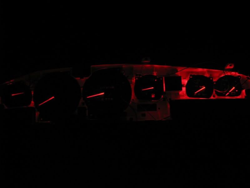
All led to this:
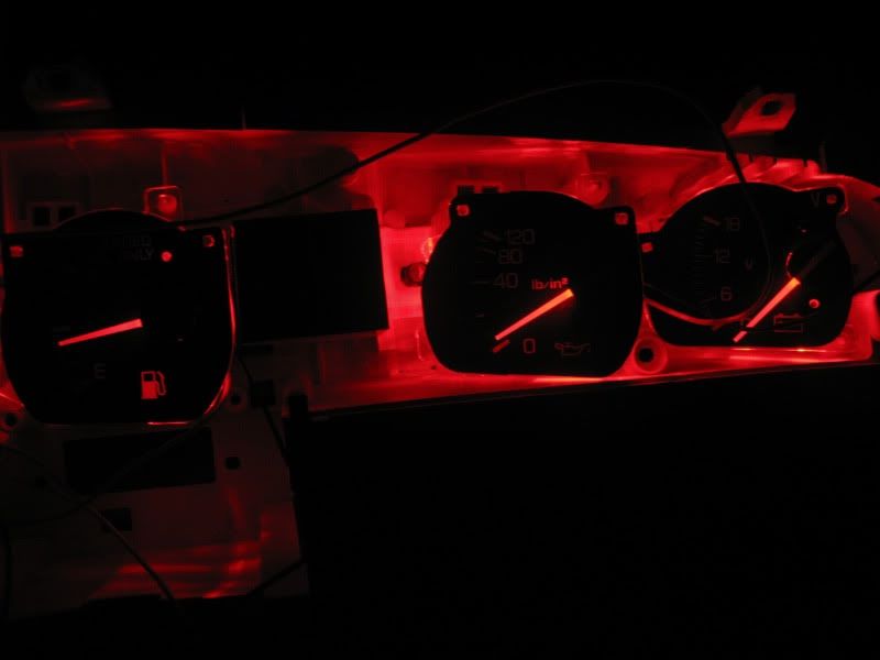
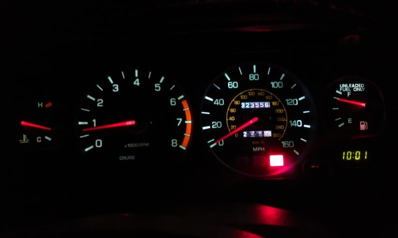
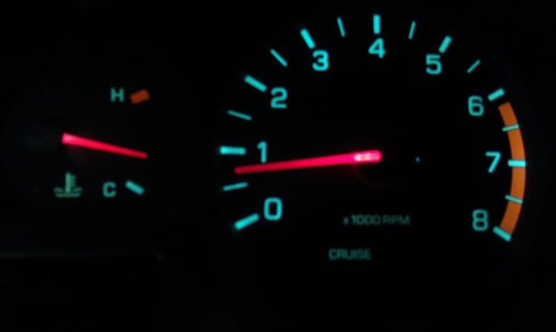
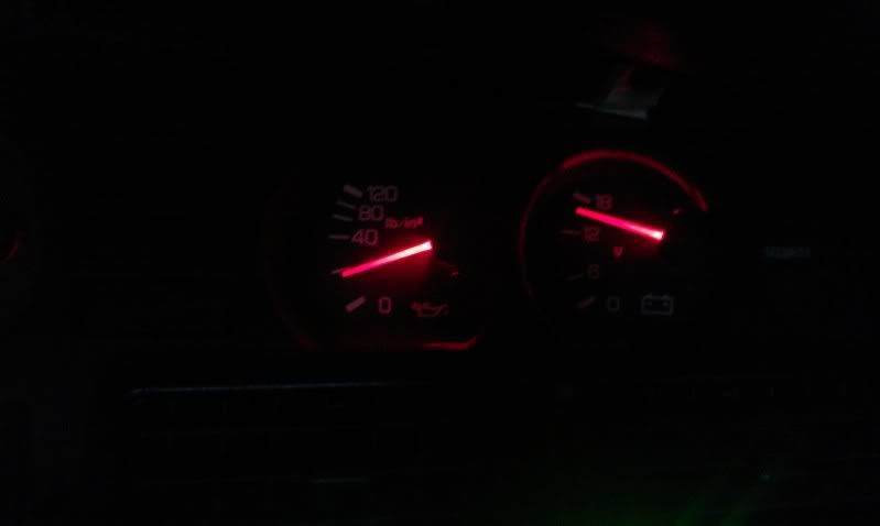
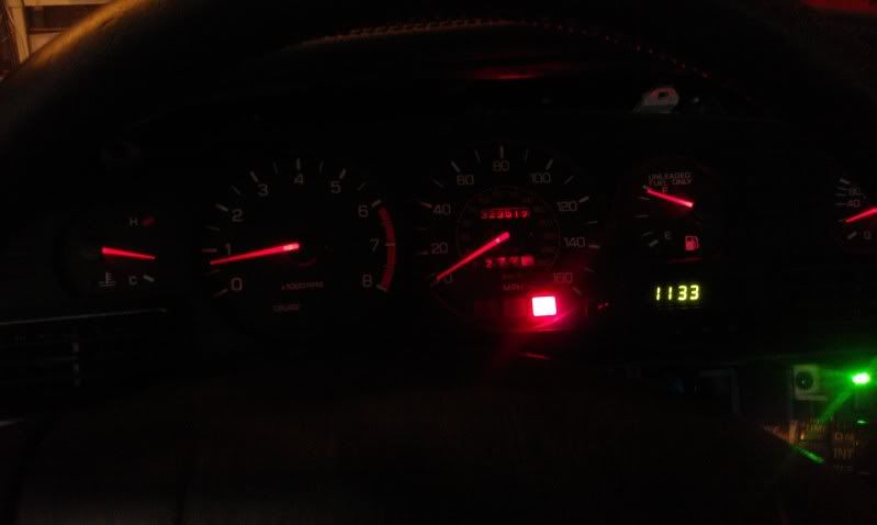
They are powered with the ignition so anytime the car is running, the needles are lit. It's pretty neat in the dawn/dust times because the needles have a little *pop* to them without actually appearing to glow. Kinda hard to explain.
I'll post a TON of pictures and write a novel on what I did in my lighting thread (See sig), but I'm not 100% happy with the turn out. Doing all this work showed me exactly how fragile and inaccurate the construction of our stock gauges are. I'm perplexed how the oil pressure gauge even functions after 20 years, let alone hold any degree of accuracy. The water temp gauge is so lightly controlled, it fluctuates under the weight of the needle. Holding the gauge at a slightly different angle changes the readout of the gauge. I can imagine it actually reads different if you're parked on a steep uphill vs steep downhill.
I'm now on a hunt for good, simple aftermarket stepper motor gauges for Water temp, Oil Pressure, Boost and AFR. Of course, the oil pressure and water temp would go in the stock locations keeping the cluster classy and functional. The other two will go in the A-pillar pod, but I'm really displeased with the quality of the Lotek pillar pod. It's really starting to bother me.
All led to this:
They are powered with the ignition so anytime the car is running, the needles are lit. It's pretty neat in the dawn/dust times because the needles have a little *pop* to them without actually appearing to glow. Kinda hard to explain.
I'll post a TON of pictures and write a novel on what I did in my lighting thread (See sig), but I'm not 100% happy with the turn out. Doing all this work showed me exactly how fragile and inaccurate the construction of our stock gauges are. I'm perplexed how the oil pressure gauge even functions after 20 years, let alone hold any degree of accuracy. The water temp gauge is so lightly controlled, it fluctuates under the weight of the needle. Holding the gauge at a slightly different angle changes the readout of the gauge. I can imagine it actually reads different if you're parked on a steep uphill vs steep downhill.
I'm now on a hunt for good, simple aftermarket stepper motor gauges for Water temp, Oil Pressure, Boost and AFR. Of course, the oil pressure and water temp would go in the stock locations keeping the cluster classy and functional. The other two will go in the A-pillar pod, but I'm really displeased with the quality of the Lotek pillar pod. It's really starting to bother me.
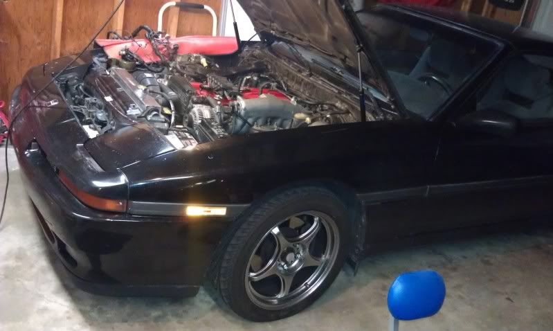
She's in the garage for the winter. After a quick night pulling the intake piping and wiring harness out it's time to start planning out where I'll move many of the components in the bay.
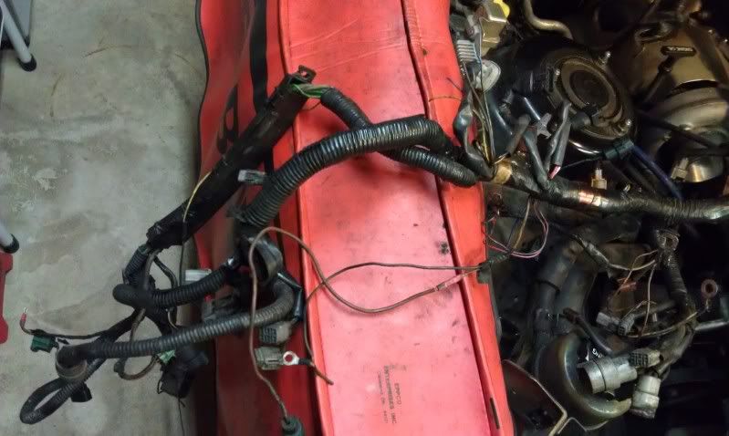
Hacked to hell wiring harness in desperate need of a 100% replacement.
Winter plan priorities:
New harness
-Reuse as little as possible from old harness
-MilSpec Tefzel wire rated to 200C and self extinguishing
-OEM connectors, as many new as possible
-Loom and wire wrap to be decided
Relocate items
-Boost Controller
-Boost gauge sender
-Charcoal canister
-Power Steering reservoir
-ignitor
-fuel pump relay
-ignitor resistor pack
(possibly coil pack and possible cruise delete)
I'd also like to add wiring into the harness to utilize a simple hidden switch that jumpers E1 and TE1 so I can check codes in cabin with the hood closed. I will also integrate some sort of kill switch that shuts down either the fuel pump or EFI circuit.
I guess that covers the priorities. Other nice-to-get done projects include:
Intercooler piping/IC. My current piping won't hold more than ~11psi. I want to run right at 11 and it's frustrating that they can pop off at any moment.
New floormats/rear carpet
Recovered steering wheel
Flow tested injectors
Wideband
Subwoofer
6.5" speaker pods
New windsheild trim
New window regulator for drivers side
New corner window pieces
Lip
Full Flow Thermostatic Oil Cooler circuit
Antenna delete (mine is currently stuck half way up/down)
30% tint
Suspension (Pretty set on Tokico shocks, totally undecided on springs and possible swaybars)
That's all I'm thinking of right now. I'm sure there's more to my realistic wish list, but it'll all come together eventually. I also decided to get a motorcycle so that'll slow things down a little too, lol.
Recommendations welcome.
Made some big progress in the last few weeks. Harness is out, half stripped, pins are mapped out, terminal types labeled, connectors ordered from Toyota. There are about half the connectors which are not available through Toyota. I have all part numbers for every connector, but some dont even show up as part numbers with Toyota dealers. Ugh.
As of now the plan is mil spec 22759/16 Tefzel wire used commonly in aviation. 150C temp rating. Wire should be $0.25-0.74 per foot. I will order solid color wire and label "striping" with colored heatshrink tubing with a clear pvc heatshrink over top. Wire wrap will likely be techflex stuff. Undecided on which variety, but I think most varieties offered will serve my purpose. So long as the continuous temp rating is above ~130C I think I should be fine.
colored heatshrink:

Clear:

Techflex sheath which will replace the hard plastic "loom" shit:


Still searching for the best source for terminals/wire seals. Many places offer them individually, but they're like $1/per which is simply unacceptable when I'm doing literally hundreds of wires. I'm hoping I can find them for a fraction of that.
Also still debating a crimping tool. Need something that will do the job properly, but I can't justify more than ~$100. I'm not making this a $2000 project, and costs are adding up, lol.
As of now the plan is mil spec 22759/16 Tefzel wire used commonly in aviation. 150C temp rating. Wire should be $0.25-0.74 per foot. I will order solid color wire and label "striping" with colored heatshrink tubing with a clear pvc heatshrink over top. Wire wrap will likely be techflex stuff. Undecided on which variety, but I think most varieties offered will serve my purpose. So long as the continuous temp rating is above ~130C I think I should be fine.
colored heatshrink:
Clear:
Techflex sheath which will replace the hard plastic "loom" shit:
Still searching for the best source for terminals/wire seals. Many places offer them individually, but they're like $1/per which is simply unacceptable when I'm doing literally hundreds of wires. I'm hoping I can find them for a fraction of that.
Also still debating a crimping tool. Need something that will do the job properly, but I can't justify more than ~$100. I'm not making this a $2000 project, and costs are adding up, lol.
Just dropped $200 on techflex sleeving and heatshrink.
Carbon Fiber for the main harness parts, Insultherm fiberglass sleeving for the spot that goes over the cams or other high heat areas, Flexo PET for most everything else.
I've already ordered all connectors I could from Toyota, now just need to order wire, terminals, seals, crimpers and.... i think that's it.
Total will probably be in the neighborhood of $900-$1100 and totally worth it.
Only issue I have with the flex sheathing is that if for any reason you need to open the harness you would have to slice it open. Not to mention running a new wire in there would be a total pita and its impossible to replace the sheathing without depinning all the connectors.
CyFi6;1787516 said:Only issue I have with the flex sheathing is that if for any reason you need to open the harness you would have to slice it open. Not to mention running a new wire in there would be a total pita and its impossible to replace the sheathing without depinning all the connectors.
Yup. Agreed. I'm debating running extra dummy wires for maft pro/speed density just in case. Depinning and redoing a section of harness won't be too bad. The larger core section might expand over connectors anyways.
I debated using the flex wrap stuff, but its nowhere near as clean looking.
Sent from my ADR6400L using Tapatalk
Ordered a Paladin crimper with open barrel terminal crimper for ~$70. I debated a pro-crimper from tyco or some other high $$ crimper, but the project cost is mounting quickly and this should do the job plenty well.

Also ordered $300 in MIL spec 22759/16 wire, about 900 feet or so. I got most solid colors and will use heatshrink to indicate stripes. Now all that remains is terminals (I still have to count out how many of each type i will need) and a few oddball connectors that aren't available from Toyota.
Also just found out one of my tires is trashed. I got them second hand and they needed replacement anyways. Looks like I'll be ordering some new tires this spring. I'm thinking BF Goodrich G-force or maybe Continental Extreme Contact. I LOVE the tread design on the G-force tire and it gets great reviews so I'm leaning towards that.
I hope you find the time to write up your instrument mods. By the way, for making little custom PCB boards, just go to this guy
http://dorkbotpdx.org/wiki/pcb_order
Use whatever CAD you like to generate the gerber files, then have them professionally made for $5 per square inch for three copies of your two layer design. Most of your boards looked like they were 1-2 sq inches, so this is really cheap.
http://dorkbotpdx.org/wiki/pcb_order
Use whatever CAD you like to generate the gerber files, then have them professionally made for $5 per square inch for three copies of your two layer design. Most of your boards looked like they were 1-2 sq inches, so this is really cheap.
3p141592654;1789446 said:I hope you find the time to write up your instrument mods. By the way, for making little custom PCB boards, just go to this guy
http://dorkbotpdx.org/wiki/pcb_order
Use whatever CAD you like to generate the gerber files, then have them professionally made for $5 per square inch for three copies of your two layer design. Most of your boards looked like they were 1-2 sq inches, so this is really cheap.
Yeah, I should get my lazy ass typing one of these days. My biggest hesitation has been uploading all the photos to photobucket. I had the camera unintentionally set to the highest quality so each pic is like 3MB and I have dozen of pics... So it'll take a while to upload everything, lol. And photobucket seems to timeout if I do more than 5-10 at a time when they're that large a file.
**Edit, oh and that guys proto board offering is super cheap. I wonder what thickness the board are though? And what the minimum size board would be. He lists a lot of specs on the actual trace and annular rings, but i dont see actual min. board dimensions. Good find and thanks for the tip!!!
I'm hoping to post solid documentation on all the wiring harness stuff too. This has been quite a scavenger hunt so far and I think it would be a good asset to the community to have all the info in a central place. It's funny how much info is needed to replicate a wire harness. I honestly didn't know what I was getting into and I'm surprised how much goes into planning this all out.
I just spent a few hours in the garage messing with the harness. I made a terminal tool according to Toyota's specs and pulled out some terminals, photographed them, found another handful of wires that are broken or that I broke while handling the harness just now. That harness was just a time-bomb waiting to leave me stranded. It will be a huge relief to get this thing replaced. My 02 sensor connector disintegrated. It no longer has locking tabs to hold the connectors in place and it's not available through Toyota... Argh. So now I have to find a different vendor that has it or change the connector entirely so something else that hopefully uses the same terminal type at least.
Oh, the joys of a massive wiring project...
Last edited:
LED Needles writeup
Well here it goes. This took a ton of labor to perfect. I'm no wiring genius and until this my circuit prototyping experience was practically zero. I'd worked on basic breadboard projects in my electronics 101 engineering course, but that was about it.
First, for a perspective, these are the SMT LED I'm dealing with.
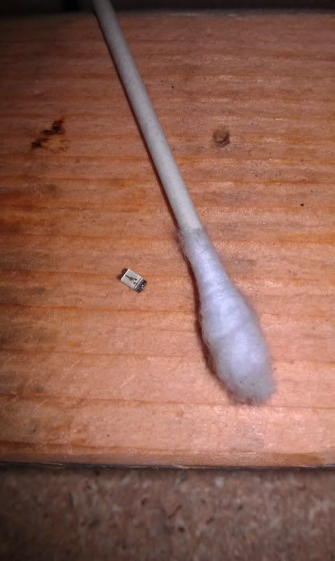
They are far from the smallest available, but are plenty small for this project. They are a 1206 package. Digikey part number 160-1167-1-ND. I got 50 of them for under $5 a year ago thinking they might come in handy at some point.
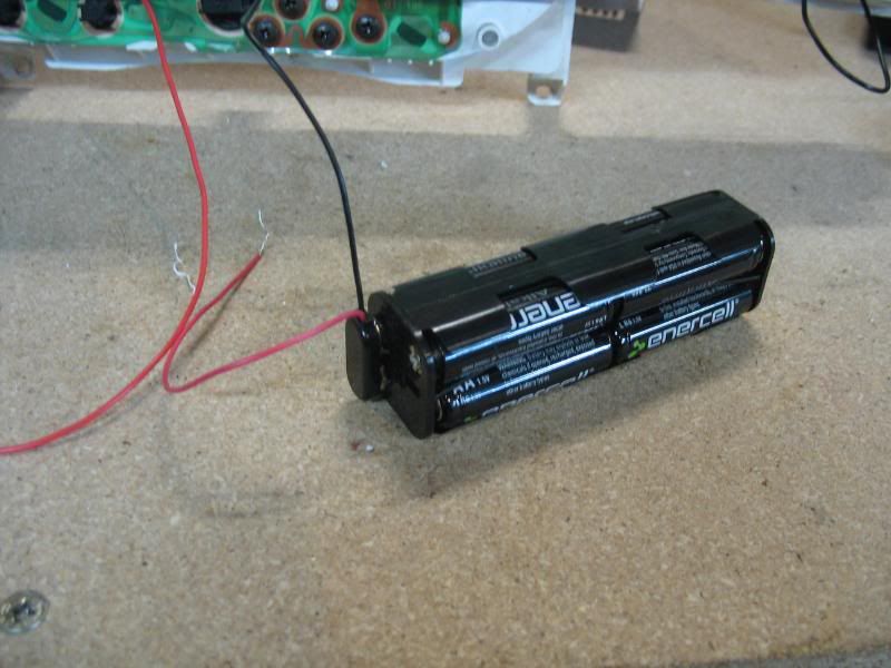
This is my power source. 8 1.5 AA batteries in series. That makes 12V for those scoring at home.
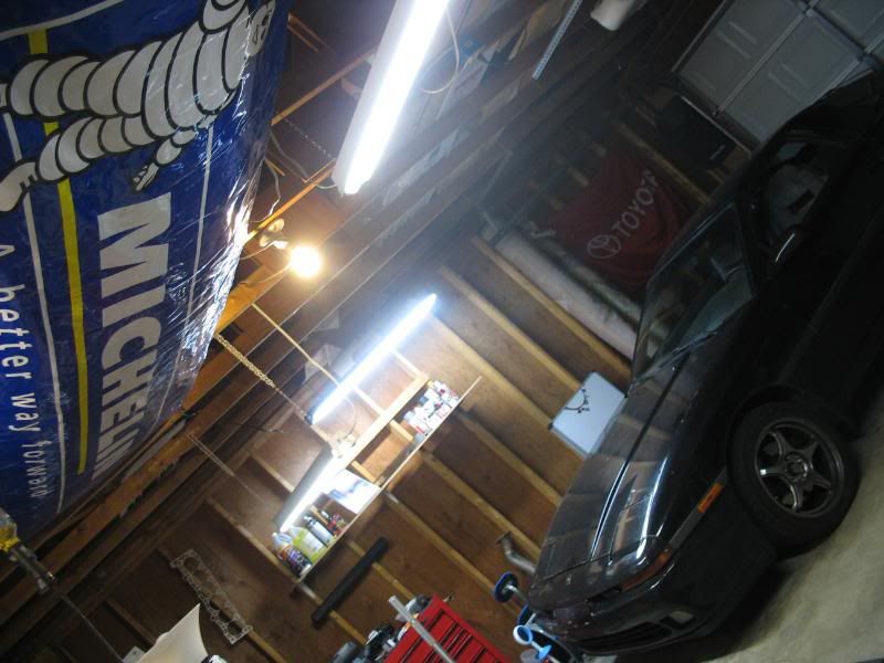
And just for shits, a picture of my garage. Nothing special, but I love it. It's a rental, but if I owned it you'd see finished walls, epoxy floor and wall storage galore. But alas, I'm still young so home ownership isn't under my belt yet and my garages are pretty basic.
So the gauge lighting concerns starts with the fact that once you update the face lighting with LED's, the needles fail to glow as brightly, especially if you pain the needles. I wanted a crisp white face and deep red needle. This means White leds in the face and red SMT (surface mount technology) LED's or SMD (surface mount diode). Mine were roughly 1mm tall which means they can fit between the gauge face and the component behind the gauge. The amount of clearance available varies from gauge to gauge. The speedometer and oil pressure gauge likely have the least amount of clearance. They were the most difficult for me. The easiest is probably the tach.
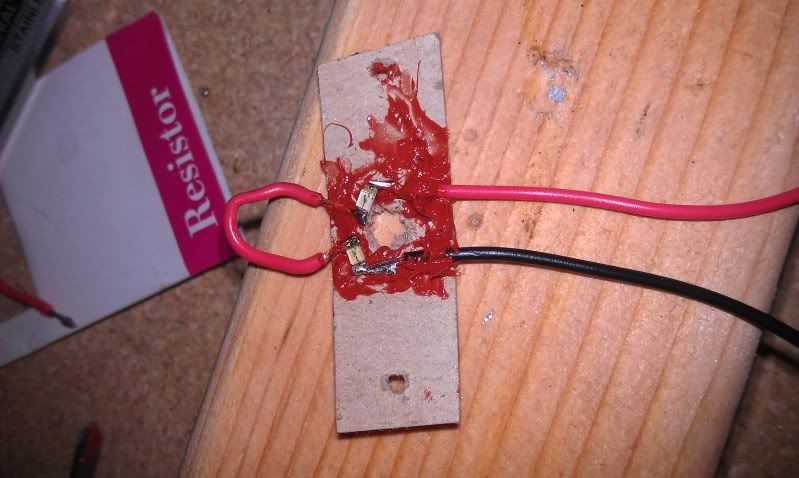
So onto design. I started with a search for a substrate. Having no experience with circuits I was lost. All i knew was I needed something very thin and something that I could stick some LED's to. To try my plan I and to make sure the LED's would light the needle correctly, I started with cardboard and an old credit card. LED's worked and lit the needle perfectly. The cardboard and/or credit card as a substrate was a horrible idea, but you probably could have guessed that.
Somehow I lost a ton of photos which would have shown exactly how I made each circuit board. At some point I'll add them back in if I find them. For now, I'll have to skip some pictures and bore you with words.
Before actually doing anymore building I measured the hell out of the gauges and the mounting areas. I measured everything in inches and to an accuracy of 0.01". I wasn't able to hold that same accuracy during the build part, but the accurate measurements were definitely helpful. The only gauges that were similar were the water temp and gas gauge; and even those had minor differences if i recall correctly. Once I had all my measurements I modeled the baords I had in mind in SolidWorks (CAD).
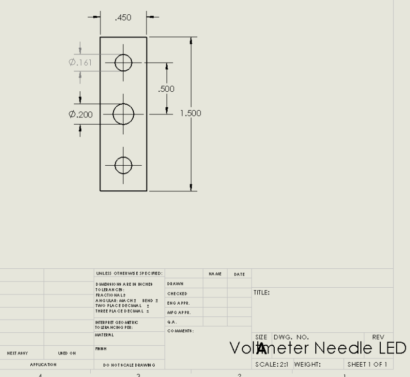
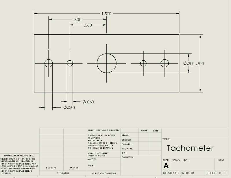
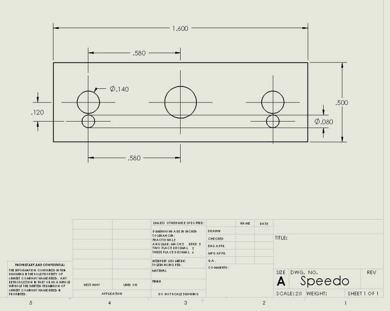
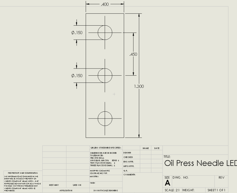
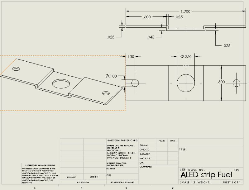
The above drawings should be right, but I had to make adjustments and I'm not positive I went back to edit all the cad files. So use that info at your own risk, lol.
Once I had everything modeled it was time to start building. A pair of locking foreceps was key to soldering with the SMD's. My soldering iron is a basic POS and made this more difficult that it could have been with a good iron. I found some proto board about 2 inches square and 2mm thick. I used a dremel to cut the boards into the correct size and then proceeded to start the wiring. The pieces all needed to be pretty thin. The speedo especially has very little clearance and has a very delicate piece of the gauge directly underneath where the LEDs are mounted. This means you have to be very sure your LED inserts will not touch the instrument. The needles on all gauges are very delicate. Any slight rubbing means the gauge is worthless and you have very little margin for error.
I had a great picture of the speedo showing exactly how tight it is, but I seem to have lost it. Imagine a very small space....
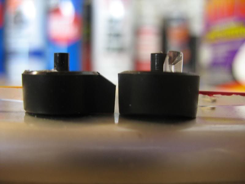
The smaller gauges all have a light guide system that relies on the face lighting to carry into the center of the gauge face, where a semicircular extrusion of clear plastic grabs the light and throws it out onto the needle. Clever design, but unfortunately it wont work with what we're doing and you need to cut it off. I used a dremel and was very, very careful.
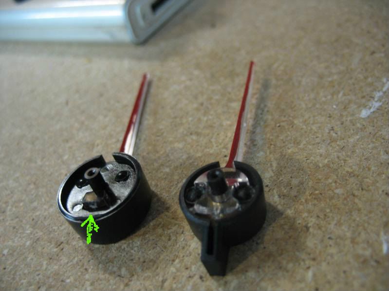
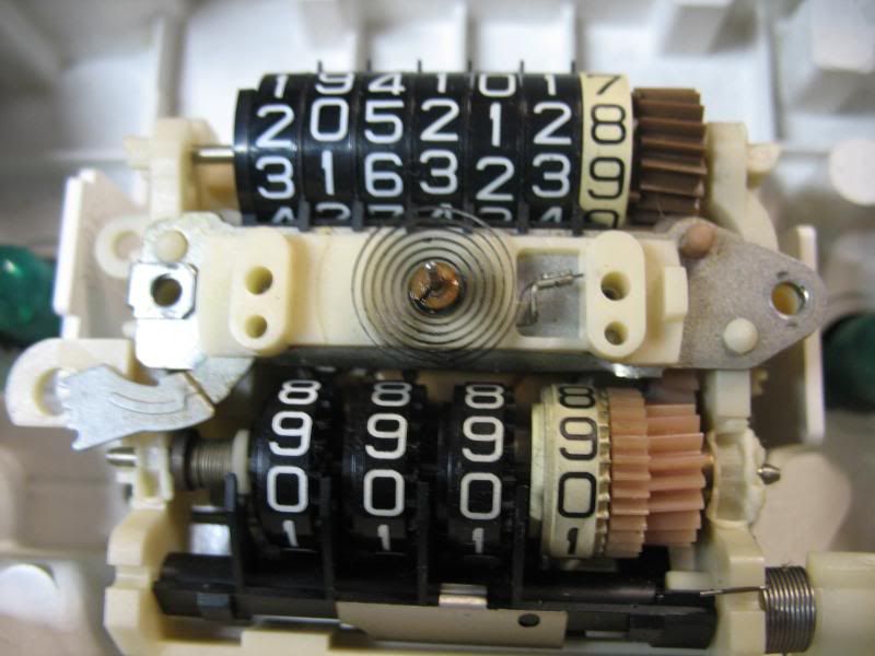
Below you can see the difference between pre 89 (my prototype dash) and 89+ (My actual car). The pre 89's have a TON of space for the needle to catch light from below. The 89+ on the left have just a small square (green arrow) to catch light for the needle. This affects how much light is needed and determines whether or not you need to drill out the gauge plastic to let more light through. My proto board (pre89) was fine leaving the plastic backing alone, but on my actual car (89+) I had to drill out the plastic entirely underneath the needle.
This is what I'm talking about:
Left alone:
Drilled out:
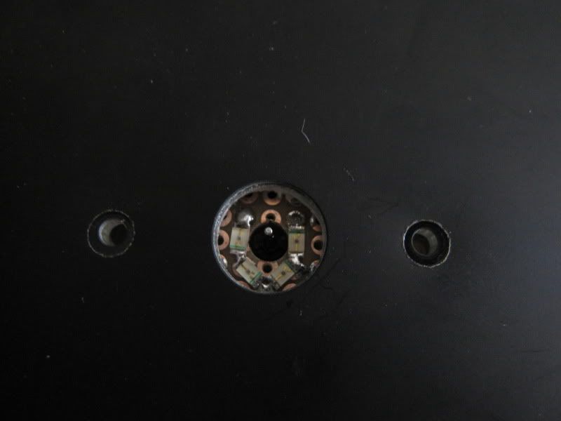
In the picture above you can see how the LED's are mounted. It's pretty basic, really. You just need to measure everything and know where you need to center the LED's.
Here's the Speedo finished:
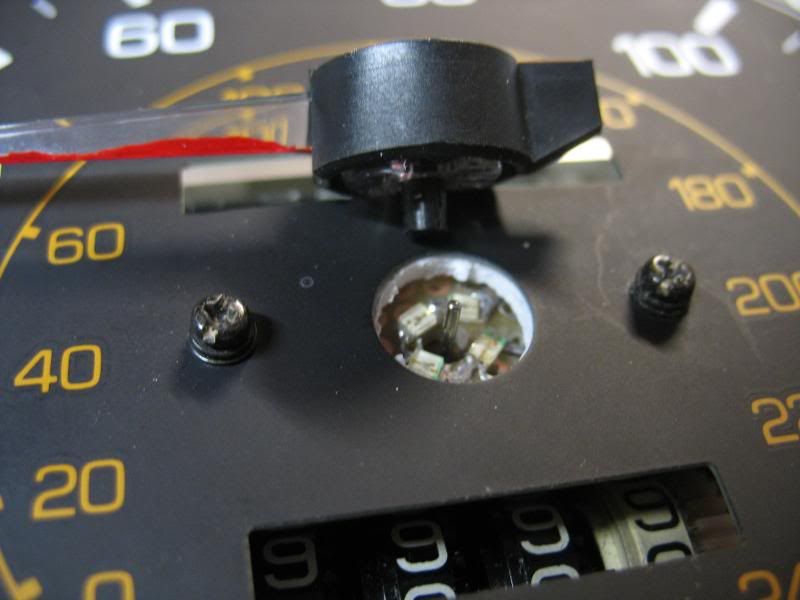
And here's what the board looked like more or less when I was done with the speedo. I had to use my dremel drill press as a mill and mill a channel for the wire. The clearance was so low that the board plus the wire (22AWG) was too thick. The problem with the speedo is that you cant have anything hanging down under the board, so the wires cant be underneath, they have to be on top.
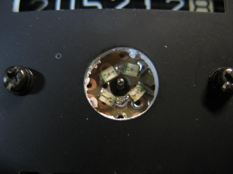
This is the speedo unit. That coil is the gauge and is incredibly sensitive. Nothing can touch it.
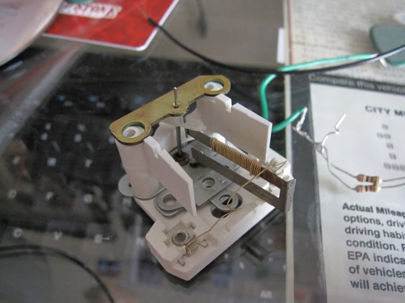
Just for shits, here is the oil pressure gauge. I dont understand how the gauge actually moves, but the whole thing is so flimsy I just cant grasp how it could be very accurate.
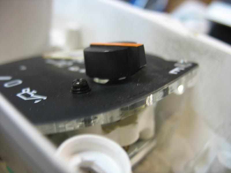
Here is one of the small gauges after already having shaved the bottom of the needle base. Clearance are very, very tight. You want to keep this clearance minimal so you have less light escaping from the center of the gauge. Light bleed will be noticable when you use two different colors for the needles vs gauges.
Continued in another post since I think i'm getting close to the one post pic limit. This will all end up in the lighting thread as well.
Well here it goes. This took a ton of labor to perfect. I'm no wiring genius and until this my circuit prototyping experience was practically zero. I'd worked on basic breadboard projects in my electronics 101 engineering course, but that was about it.
First, for a perspective, these are the SMT LED I'm dealing with.
They are far from the smallest available, but are plenty small for this project. They are a 1206 package. Digikey part number 160-1167-1-ND. I got 50 of them for under $5 a year ago thinking they might come in handy at some point.
This is my power source. 8 1.5 AA batteries in series. That makes 12V for those scoring at home.
And just for shits, a picture of my garage. Nothing special, but I love it. It's a rental, but if I owned it you'd see finished walls, epoxy floor and wall storage galore. But alas, I'm still young so home ownership isn't under my belt yet and my garages are pretty basic.
So the gauge lighting concerns starts with the fact that once you update the face lighting with LED's, the needles fail to glow as brightly, especially if you pain the needles. I wanted a crisp white face and deep red needle. This means White leds in the face and red SMT (surface mount technology) LED's or SMD (surface mount diode). Mine were roughly 1mm tall which means they can fit between the gauge face and the component behind the gauge. The amount of clearance available varies from gauge to gauge. The speedometer and oil pressure gauge likely have the least amount of clearance. They were the most difficult for me. The easiest is probably the tach.
So onto design. I started with a search for a substrate. Having no experience with circuits I was lost. All i knew was I needed something very thin and something that I could stick some LED's to. To try my plan I and to make sure the LED's would light the needle correctly, I started with cardboard and an old credit card. LED's worked and lit the needle perfectly. The cardboard and/or credit card as a substrate was a horrible idea, but you probably could have guessed that.
Somehow I lost a ton of photos which would have shown exactly how I made each circuit board. At some point I'll add them back in if I find them. For now, I'll have to skip some pictures and bore you with words.
Before actually doing anymore building I measured the hell out of the gauges and the mounting areas. I measured everything in inches and to an accuracy of 0.01". I wasn't able to hold that same accuracy during the build part, but the accurate measurements were definitely helpful. The only gauges that were similar were the water temp and gas gauge; and even those had minor differences if i recall correctly. Once I had all my measurements I modeled the baords I had in mind in SolidWorks (CAD).
The above drawings should be right, but I had to make adjustments and I'm not positive I went back to edit all the cad files. So use that info at your own risk, lol.
Once I had everything modeled it was time to start building. A pair of locking foreceps was key to soldering with the SMD's. My soldering iron is a basic POS and made this more difficult that it could have been with a good iron. I found some proto board about 2 inches square and 2mm thick. I used a dremel to cut the boards into the correct size and then proceeded to start the wiring. The pieces all needed to be pretty thin. The speedo especially has very little clearance and has a very delicate piece of the gauge directly underneath where the LEDs are mounted. This means you have to be very sure your LED inserts will not touch the instrument. The needles on all gauges are very delicate. Any slight rubbing means the gauge is worthless and you have very little margin for error.
I had a great picture of the speedo showing exactly how tight it is, but I seem to have lost it. Imagine a very small space....
The smaller gauges all have a light guide system that relies on the face lighting to carry into the center of the gauge face, where a semicircular extrusion of clear plastic grabs the light and throws it out onto the needle. Clever design, but unfortunately it wont work with what we're doing and you need to cut it off. I used a dremel and was very, very careful.
Below you can see the difference between pre 89 (my prototype dash) and 89+ (My actual car). The pre 89's have a TON of space for the needle to catch light from below. The 89+ on the left have just a small square (green arrow) to catch light for the needle. This affects how much light is needed and determines whether or not you need to drill out the gauge plastic to let more light through. My proto board (pre89) was fine leaving the plastic backing alone, but on my actual car (89+) I had to drill out the plastic entirely underneath the needle.
This is what I'm talking about:
Left alone:
Drilled out:
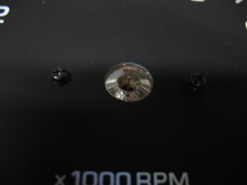
In the picture above you can see how the LED's are mounted. It's pretty basic, really. You just need to measure everything and know where you need to center the LED's.
Here's the Speedo finished:
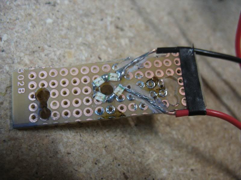
And here's what the board looked like more or less when I was done with the speedo. I had to use my dremel drill press as a mill and mill a channel for the wire. The clearance was so low that the board plus the wire (22AWG) was too thick. The problem with the speedo is that you cant have anything hanging down under the board, so the wires cant be underneath, they have to be on top.
This is the speedo unit. That coil is the gauge and is incredibly sensitive. Nothing can touch it.
Just for shits, here is the oil pressure gauge. I dont understand how the gauge actually moves, but the whole thing is so flimsy I just cant grasp how it could be very accurate.
Here is one of the small gauges after already having shaved the bottom of the needle base. Clearance are very, very tight. You want to keep this clearance minimal so you have less light escaping from the center of the gauge. Light bleed will be noticable when you use two different colors for the needles vs gauges.
Continued in another post since I think i'm getting close to the one post pic limit. This will all end up in the lighting thread as well.
Last edited:
nice progress, you should try doing the printable circuit board with laser printers it worked really well for Albert and I when we were doing our needle lights. The supplies are cheap and make life easier for sokdering in the smd leds. Also if u get to much splash on the top of the face put a little brass ring in the bass of the needle, it can be made from brass tubing from an ACE hardware or craft store. Cant wait for the other pics your going to post up.
Well the wiring harness is still under way. Tracking down brand new terminal pins is a BITCH. Very difficult to source.
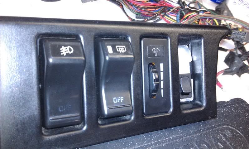
Anyways, while waiting to find all the terminals, I made a little bracket/brace for some switches I got. Doesn't look pretty now, but after a matte black paint job it should blend it pretty well. The first switch will be for a diagnostics jumper. Checking codes you say? Simply flip the switch and turn the key.
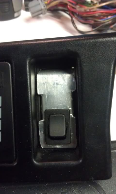
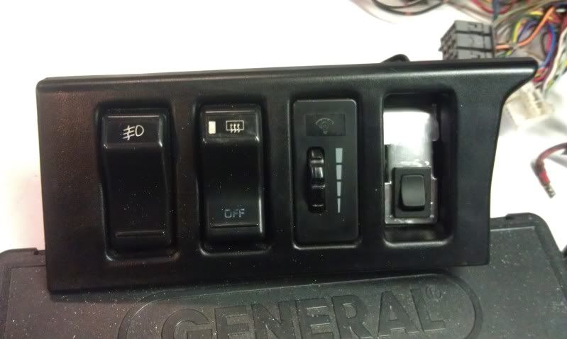
Before I start the harness assembly I'll take a picture of all the parts laid out. Should be a BIG picture, lol.
Anyways, while waiting to find all the terminals, I made a little bracket/brace for some switches I got. Doesn't look pretty now, but after a matte black paint job it should blend it pretty well. The first switch will be for a diagnostics jumper. Checking codes you say? Simply flip the switch and turn the key.
Before I start the harness assembly I'll take a picture of all the parts laid out. Should be a BIG picture, lol.