Hi guys, thought i should start a thread about the new engine i'm building for my Cressida (yeah yeah, its not a supra, but close enough!)
For those that dont know, 7m's are kinda my thing, GE's in particular. I'm not really into turbos.
What i do like is a nice responsive high rpm NA screamer, which built properly the 7m-ge is quite good at.
The motor will be run on dedicated LPG (Propane) which is great as the 110RON out of the bowser means you can run silly compression and it loves ignition timing. Not to mention it is cheap as chips here in Australia and allows a lot of the EFI crap to be deleted from the engine.
Let's start with the head. Last year i bought a big new milling machine which i converted to CNC, and i wanted to CNC port a 7m head. There was so much f'ing work in coding this up, and a lot of machine time for the actual porting!
Being only a 3 axis CNC i cant get absolutely everywhere in the ports, but i was able to work on the important bits, being the valve bowls and combustion chambers. Still, being CNC it has one very distinct advantage in that each port/bowl/chamber is exactly the same as the next. Also it beats the hell out of spending 40 hours with your die grinder....
All the machining work was done concentric to each valve seat (or port)
The intake ports were left alone past the bowls as they are already too big, however the exhausts were opened up by 1mm at the port exit to maintain a reversion dam, and this bigger diameter was carried back to where the 2 valves join into 1 port which according to my cross sectioning was the most restricted part of the exhaust port.

you can sort of see here how much meat was taken out of the mid-port area

end result without valves

with valves

While we're on the exhaust side, remember that pesky EGR hole in the #6 exhaust port, normally blanked off by a plate on the rear of the head in ADM cars... well that's gone now.

as in completely gone, i press fit a plug in the hole before milling out the port and the extra bits of plug were cut away with the rest of the port....

The chambers were actually left with the standard cloverleaf shape to maintain squish, but the shrouding around the valves was heavily cut back. I did a 3 angle valve job and the 3rd angle then leads into a large radius into the chamber. The radius is in fact the same as the valve radius so in theory maximising the flow without removing more meat than necessary (cant loose to much comression!)
So here is the original chamber, complete with valve shrouding. at low lift in particular they are quite restricted, with max lift not a lot better TBH

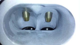
New chambers and bowls. The seats were bored out 2mm and again there are some funky radii going on in the bowl. The valve guides were also milled with an aerofoil shape on the inlet to split air around the valve stem, and create a low pressure point behind it which is otherwise a dead area of the port. a simple chamfer is enough on the exhaust.


An idea of the various curves and arcs involved in the valve bowl toolpath. No CAM, the code was all written in MS Excel

For those that dont know, 7m's are kinda my thing, GE's in particular. I'm not really into turbos.
What i do like is a nice responsive high rpm NA screamer, which built properly the 7m-ge is quite good at.
The motor will be run on dedicated LPG (Propane) which is great as the 110RON out of the bowser means you can run silly compression and it loves ignition timing. Not to mention it is cheap as chips here in Australia and allows a lot of the EFI crap to be deleted from the engine.
Let's start with the head. Last year i bought a big new milling machine which i converted to CNC, and i wanted to CNC port a 7m head. There was so much f'ing work in coding this up, and a lot of machine time for the actual porting!
Being only a 3 axis CNC i cant get absolutely everywhere in the ports, but i was able to work on the important bits, being the valve bowls and combustion chambers. Still, being CNC it has one very distinct advantage in that each port/bowl/chamber is exactly the same as the next. Also it beats the hell out of spending 40 hours with your die grinder....
All the machining work was done concentric to each valve seat (or port)
The intake ports were left alone past the bowls as they are already too big, however the exhausts were opened up by 1mm at the port exit to maintain a reversion dam, and this bigger diameter was carried back to where the 2 valves join into 1 port which according to my cross sectioning was the most restricted part of the exhaust port.
you can sort of see here how much meat was taken out of the mid-port area
end result without valves
with valves
While we're on the exhaust side, remember that pesky EGR hole in the #6 exhaust port, normally blanked off by a plate on the rear of the head in ADM cars... well that's gone now.
as in completely gone, i press fit a plug in the hole before milling out the port and the extra bits of plug were cut away with the rest of the port....
The chambers were actually left with the standard cloverleaf shape to maintain squish, but the shrouding around the valves was heavily cut back. I did a 3 angle valve job and the 3rd angle then leads into a large radius into the chamber. The radius is in fact the same as the valve radius so in theory maximising the flow without removing more meat than necessary (cant loose to much comression!)
So here is the original chamber, complete with valve shrouding. at low lift in particular they are quite restricted, with max lift not a lot better TBH
New chambers and bowls. The seats were bored out 2mm and again there are some funky radii going on in the bowl. The valve guides were also milled with an aerofoil shape on the inlet to split air around the valve stem, and create a low pressure point behind it which is otherwise a dead area of the port. a simple chamfer is enough on the exhaust.
An idea of the various curves and arcs involved in the valve bowl toolpath. No CAM, the code was all written in MS Excel


")