
hey i guys i got another question i was examining my ecu and then looking at the "pre 89 diagram" and my ecu clips are totally the opposite way....my HAC is on the left and the clips go in direct opposite order...this is confusing me and i dont wanna mess up the harness or the ecu because the car needs to be done by the 1st because it is going to the track in mission b.c.
As Requested: MaftPro Install writeup
- Thread starter NJsupraA70
- Start date
You are using an out of date browser. It may not display this or other websites correctly.
You should upgrade or use an alternative browser.
You should upgrade or use an alternative browser.
indy_mk3;1061117 said:hey i guys i got another question i was examining my ecu and then looking at the "pre 89 diagram" and my ecu clips are totally the opposite way....my HAC is on the left and the clips go in direct opposite order...this is confusing me and i dont wanna mess up the harness or the ecu because the car needs to be done by the 1st because it is going to the track in mission b.c.
Two things.... first some help, and then some advice:
The help:
You are most likely looking at the diagram from the wrong orientation. The other possibility is that you have a crossover year ecu. The best thing to do is get ahold of a TSRM for your EXACT model year, and look in the EFI section at the ECU connector diagrams. Then you'll know exactly which terminal, and hence which harness wire to tap into.
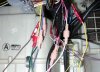
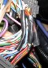
Secondly, get yourself some proper crimp connectors which look like my example pic. You solder the wires into the ECU harness wires, and then simply plug and unplug the maftpro harness as needed.
The advice:
Trying to do this work on a deadline is a recipe for trouble. Even after you get the maftpro properly hooked up, you still need to get a handle on the correct basic parameters, and after that you have to tune the car so you don't run too lean or rich. How do you expect to do all this in five days?
You can try of course, but I am worried that if you cut corners to get it done on time so you can drag race at mission, then shit tends to happen!
")
Attachments
ok thanks man and i was just gonna ask in the pic it looks like you cut the wires coming from the ecu and connected them straight to the maft pro harness leaving the harness side all disconnected...i thought you only do that to the KS green wire and for the rest you cut your supposed to cut the wires from the ecu and then connect the maft pro wires in with the wires coming from the harness side as well. And my car has had a weird life and about 4 different engines that i know of and who know's how many owners and by looking at the ecu im positive it has been swapped but it does say "87 supra M/T"
indy_mk3;1062118 said:ok thanks man and i was just gonna ask in the pic it looks like you cut the wires coming from the ecu and connected them straight to the maft pro harness leaving the harness side all disconnected...i thought you only do that to the KS green wire and for the rest you cut your supposed to cut the wires from the ecu and then connect the maft pro wires in with the wires coming from the harness side as well. And my car has had a weird life and about 4 different engines that i know of and who know's how many owners and by looking at the ecu im positive it has been swapped but it does say "87 supra M/T"
Do not cut ANY ecu wires besides the KS! There is no need to unless you are getting into more advanced things like timing control.
If the manual says "tap into", then take the insulation off a 2cm section of the ecu harness about 6-10cm back from the connector (I use a small wire stripper to pinch the plastic at each end and an exacto knife to cut along the length), but do NOT cut the wires.
Then take the correct maftpro harness wire, cut a 10-20cm length off, strip one end, and wrap it around the exposed section on the ecu harness wire. Align the wires parallel to eachother as opposed to perpendicular. Solder this piece. Then wrap it in electrical tape.
Strip the other end of the short piece, and crimp one of the connectors you see in place. Connect it to the crimp connector you put on the maftpro harness wire, and you're done.
If the manual says "splice", that is the only time you actually need to cut an ecu wire.
The pic I attached shows tapped wires coming from the ecu harness. The extra wires coming out the top of the tape go to the connectors you can see in the previous picture. If you can get shrinking tape for this, it's even better!
Attachments
Last edited:
JimR;1062478 said:Do not cut ANY ecu wires besides the KS! There is no need to.
Just for clarification purposes, there are a couple configurations where this isn't the case. A couple features have been added since that manual was written that do require more wires to be cut and spliced. Examples: ETPS and timing control.
CRE;1062482 said:Just for clarification purposes, there are a couple configurations where this isn't the case. A couple features have been added since that manual was written that do require more wires to be cut and spliced. Examples: ETPS and timing control.
Good call. I was actually second guessing that myself when I started thinking about ALL applications and configs.
ok so i got the maft pro all wired up into the ecu and know i have more questions! yay!
soo my question is that ive got an LC-1 innovate wideband but i have not hoooked it up yet...but on the diagram it says the "orange" wire goes to the wideband controllers's "output" signal and that the "purple" wire goes to the wideband's ground. Know my question is that can i run these wires into my stock 02 sensor?? Do i really have to hook up my LC-1 for the maftpro to work properly?
soo my question is that ive got an LC-1 innovate wideband but i have not hoooked it up yet...but on the diagram it says the "orange" wire goes to the wideband controllers's "output" signal and that the "purple" wire goes to the wideband's ground. Know my question is that can i run these wires into my stock 02 sensor?? Do i really have to hook up my LC-1 for the maftpro to work properly?
indy_mk3;1069162 said:ok so i got the maft pro all wired up into the ecu and know i have more questions! yay!
soo my question is that ive got an LC-1 innovate wideband but i have not hoooked it up yet...but on the diagram it says the "orange" wire goes to the wideband controllers's "output" signal and that the "purple" wire goes to the wideband's ground. Know my question is that can i run these wires into my stock 02 sensor?? Do i really have to hook up my LC-1 for the maftpro to work properly?
I'm not sure why you'd want to run those wires to the stock o2 sensor, you can program the second output to emulate the narrowband o2 and feed that signal to the ecu, replacing the stock o2's signal
Do you need to hook up the LC-1 to the MAFT Pro? No, but to get all the functionality and logging abilities, you do need to, and it's only 2 wires to hook up, so simple, it's stupid not to!
http://www.fullthrottletech.com/showthread.php?t=2223
Oh, and btw, in the context you are using it, it is spelled now
If anyone has updated or better diagrams, and any additional info to add in regards to new features please PM me with them and I will add them to the original post. Keep in mind I havent been in the game for 2 years so I am sure there is alot out there that could be added. thanks
ok so ive got the maft pro's wires all wired in and now i started to wire in the LC-1 and ran into one issue. On the diagram that "Jaguar 5" posted from throttle tech it shows that you attach the brown analog wire into the maft pro's orange wire but what i dont understand is that in my LC-1 kit it shows the brown wire being "analog output 2".....so what do i do with the yellow wire? because its the "analog output 1" ..?
indy_mk3;1070165 said:ok so ive got the maft pro's wires all wired in and now i started to wire in the LC-1 and ran into one issue. On the diagram that "Jaguar 5" posted from throttle tech it shows that you attach the brown analog wire into the maft pro's orange wire but what i dont understand is that in my LC-1 kit it shows the brown wire being "analog output 2".....so what do i do with the yellow wire? because its the "analog output 1" ..?
Please go read the LC-1 manual. It tells you what each analog output does. It should then be clear what you need to do. If not, post up that you have read the LC-1 and the maftpro user manuals so we know you have done your homework.
JimR;1071091 said:Please go read the LC-1 manual. It tells you what each analog output does. It should then be clear what you need to do. If not, post up that you have read the LC-1 and the maftpro user manuals so we know you have done your homework.
ok first of all chill...ive read all the pages on the maftpro and LC1 manuals and ive talked to duane and dave, and im just trying to get this thing set. And you know what i actually got it figured out and YES the LC1 is working properly now and the car is running properly. Now i just have to tune the AFR and then the boost slowly. But thanks for checking on my homework. :sadwavey:
FYI: Timing control has been fixed.
See here for details
http://www.fullthrottletech.com/showthread.php?t=4152&page=4
See here for details
http://www.fullthrottletech.com/showthread.php?t=4152&page=4
I encountered the same problems with the instructions and the diagrams being in disagreement. I finally figured it out and got it running. I also went ahead and made a more proper diagram that actually shows which wires to splice and which to tap. I posted this in one of the many threads, can't remember which one. Keep in mind, this is for the 89+ 7mgte ECU.

ok, i've read all the posts on this, i'm on the edge of buying one, but i got a few newb questions.
1.where can i get just the wideband O2 sensor for it.-i wouldn't need a gauge right because it takes it place??
2.if i get the boost solenoid(70$) can i control boost on a upgraded CT-26
3. what does the 3 Bar MAP sensor do for me(70$)
i got a 86.5 Doing the NA-Turbo upgrade. i think this would be VERY important for me to control A/F ratio.
ANY advice is greatly appreciated.
thanks guys.
dumbo;1089198 said:ok, i've read all the posts on this, i'm on the edge of buying one, but i got a few newb questions.
1.where can i get just the wideband O2 sensor for it.-i wouldn't need a gauge right because it takes it place??
2.if i get the boost solenoid(70$) can i control boost on a upgraded CT-26
3. what does the 3 Bar MAP sensor do for me(70$)
i got a 86.5 Doing the NA-Turbo upgrade. i think this would be VERY important for me to control A/F ratio.
ANY advice is greatly appreciated.
thanks guys.
1. you really should also have a wideband gauge attached as well for visual warning while driving. innovate LC1 with no gauge is fairly cheap. Zeitronix with no gauge is also comparable. I still say you should have a gauge but you can get a cheaper analogue wideband gauge to attach to the analogue output of either wideband controller.
2. the boost controller can controll the boost signal to ANY turbo.
3. the MAP sensor allows you to DELETE your MAF (air flow sensor) to run speed density mode. Well worth the $$