
I have just finished my Walbro install and 12V Relay mod in my car with the help of earlier threads by Shaeff (who held my hand through this process) and another thread that I can't find right now. Shaeff's relay thread is very good, and should be enough for most everyone to follow. He had diagrams to look at, but the Walbro thread I read had none. I hope I can lay this out where others like me who have no idea what to expect can now have a better idea what to do before they start. I'm gonna try to show every steap along the way, and I will try my best to describe what to do the best that I can. There will be quite a few pictures, but there are a couple that I failed to take a picture of. I did not take any pictures of the re-installing of any of the parts, as they should be self explanatory.
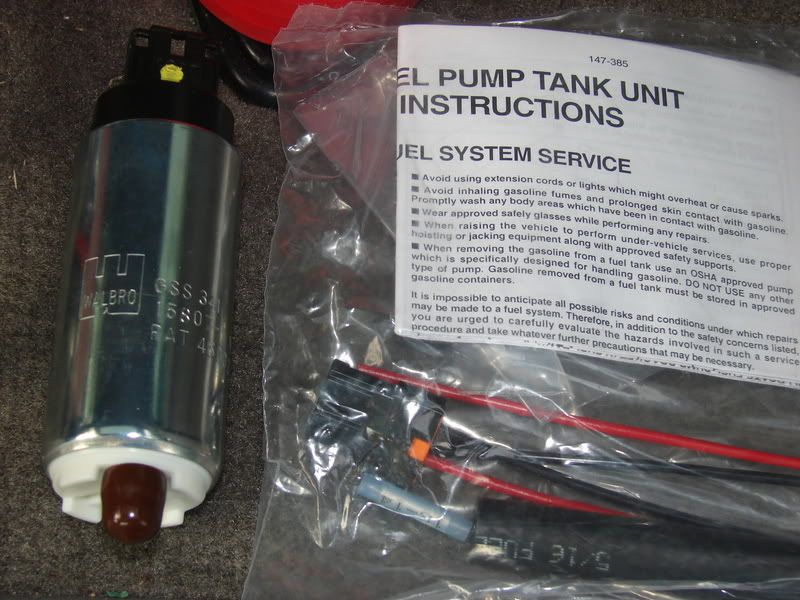
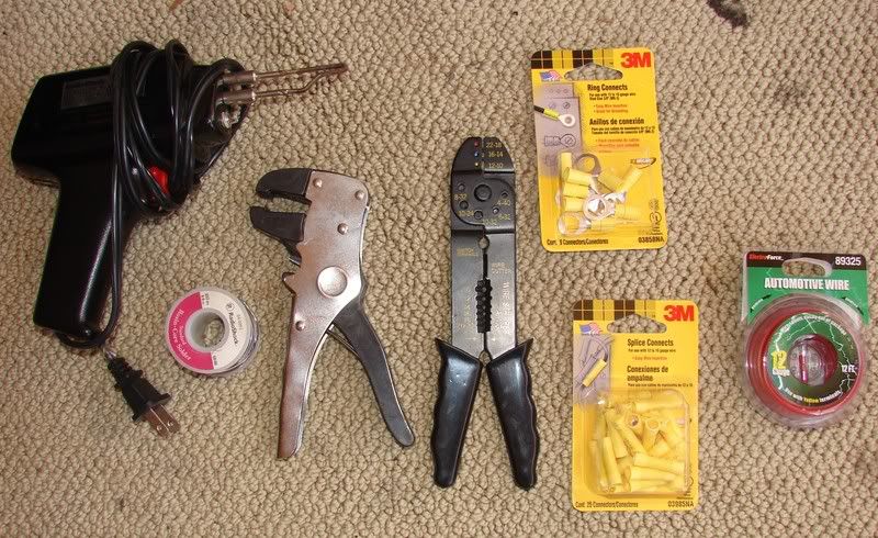
Before we get started we must first see the parts in question, and what you are gonna need to do the job. I'm assuming that if you are going to do the job that you do have a jack, jackstands, and basic hand tools. Here you will see pictures of the Walbro pump kit, and most of the electrical pieces needed. I'm showing my sodering tool that I personally did not use. I used the butt connectors provided in the kit, and crimped them on.
Use a fuse holder like this, its water proof, uses a more common style of fuse, and all around is just better.

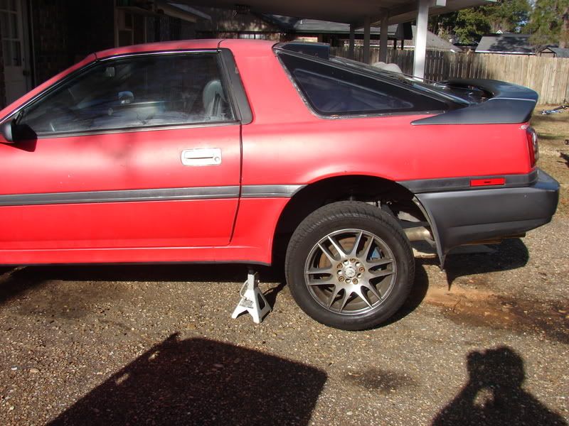
Next, we are going to prepare the car for the job by jacking the car from under the differential, and place jackstands in front of the rear wheels. I chocked the front wheel of the car to keep it from rolling backwards as the jack goes up. Then once the car was on the stands, I chocked it from rolling forward and falling off the stands with me under the car. Sorry no pictures of the chocks. You can use all types of things to do it with. A 2x4 or brick will work fine. I use a triangle rubber truck chock.
Now we're ready to pull the tank. You must first drain the tank, so try to plan this when you are low on fuel. I drained my little bit of fuel into a 5 gallon bucket. My car had been a shell fo so long I wouldn't dare re-use mine, but you can if you have fresh gas. All you need to drain the tank is a 3/8 extension on your ratchet. You then remove the round cover over the wires in your hatch. You only have to disconnect two plugs in there. Remove the 4 screws on the black plastic cover in your gas compartment, and remove the gas cap. Next you will disconnect the 3 fuel lines found on the back side of the tank. I used two crescent wrences, so I can't give you sizes here. The metal fuel line is said to give many people trouble, and may need to be replaced if you tear it up getting it loose. I used some PB Blaster on mine, and went and read my Walbro instructions while it worked it's magic. Mine came off without any trouble. Then you have two brackets with 2 12mm bolts each just inside the rear metal bumper, and 2 17mm nuts on the other end of the gas tank straps near the fuel lines. That's all you do to get the tank out. Here's pictures of everything mentioned there. Only one of the two brackets, and one of the two 17mm nuts are shown.
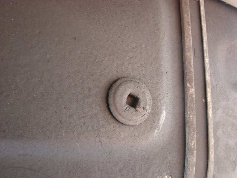
drain plug:
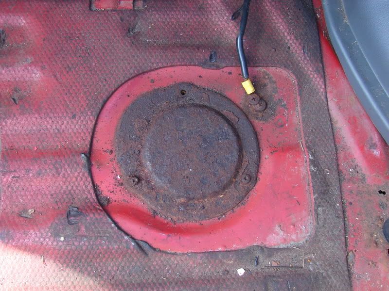
Hatch access panel (this rusty panel was pitched for a better one from my parts car)
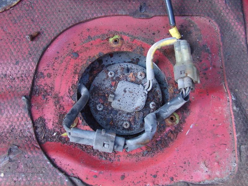
Fuel pump wiring plugs
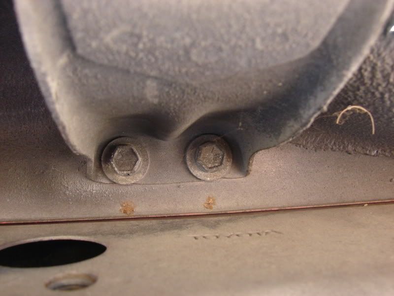
rear brakets (2 of these)
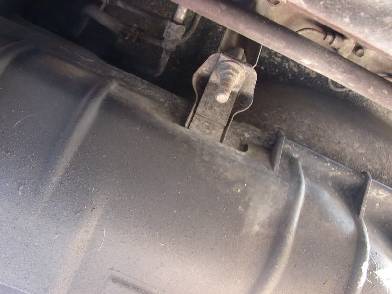
17mm nuts near fuel lines (2 of these)
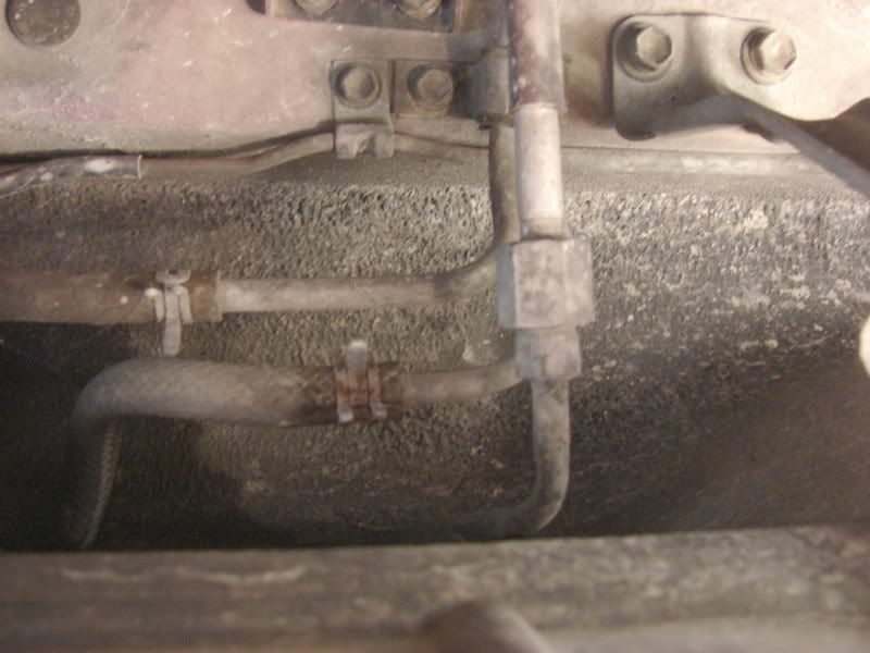
Fuel Lines Just squeeze the clamps and move the back. Twist hose around in the line, and pull it free.
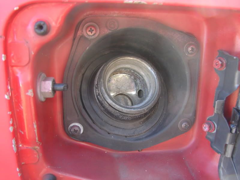
Remove gas cap and these 4 screws
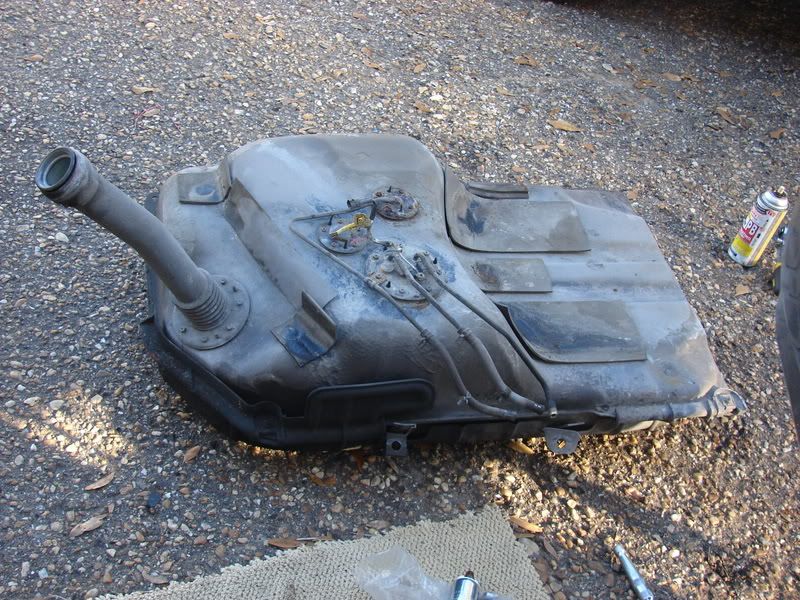
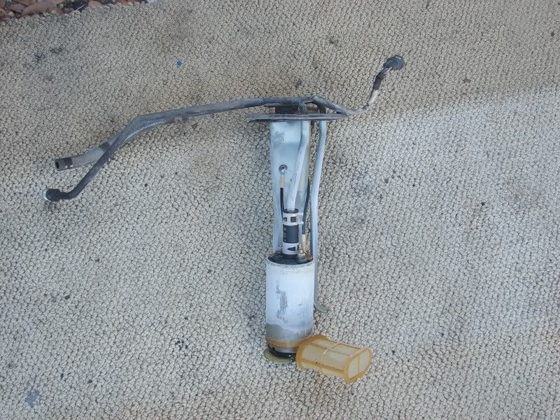
Tank removed from the car with fill nozzle still attatched
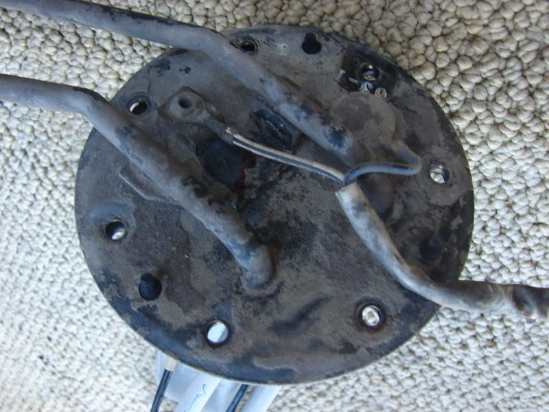
Now that the tank is out, you are at the easy part, which is actually swapping out the fuel pump. I found this to be the easiest part of the three phases (removal/install of the tank, pump swap, wiring 12V mod) of this job. You are taking out the piece with the two hoses running from it. There are 8 screws (you can use an 8MM socket too). Once it is out, you cut the two wires leading from the pump to the top of the bracket you just removed. You will plug in the harness into the pump, and use the butt connectors provided in the kit to connect the wires to the that you cut. Pay attention to positive negative here! You can soder these wires if you would like, and even use shrink tubing to cover that if you wish. Replace the hose at the top with the new hose provided. Place the new pump into the bracket, and zip tie it to the bracket. You just installed your pump, put it back into the tank. I waited until I had my wires for my 12Vmod wer done there. I used a lot of wire, and cut it down later.
Pump bracket
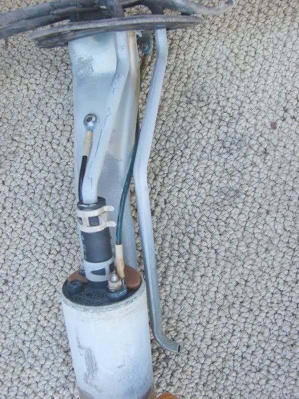
old pump
close up to see wires you will cut
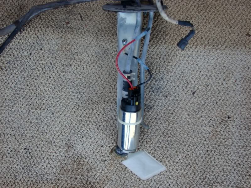
New pump installed
I will update again with 12V mod info and pics as soon as I get time this evening.
Now onto the wiring. I leaned heavily on this thread from Shaeff, as I am not very electrically inclined. Make sure you disconnect the negative battery cable before you proceed with this part.
http://www.supramania.com/forums/showthread.php?t=9417
That thread has a shot of a 12V relay, and a diagram of what wires to put where, with a list of what each wire is. He tells the story almost exactly as I did mine. I ran my relay to the bolt on the passenger side of the black part that supports the trunk board. Located there, it is raised just enough off of the floor, and just barely under the trunk board surface. Then I ran my wires underneath the trunkboard out of the way.I will show in pictures what Shaeff describes so well in his thread. He also uses this wonderful diagram.
http://www.supramania.com/forums/attachment.php?attachmentid=3420&d=1133647348
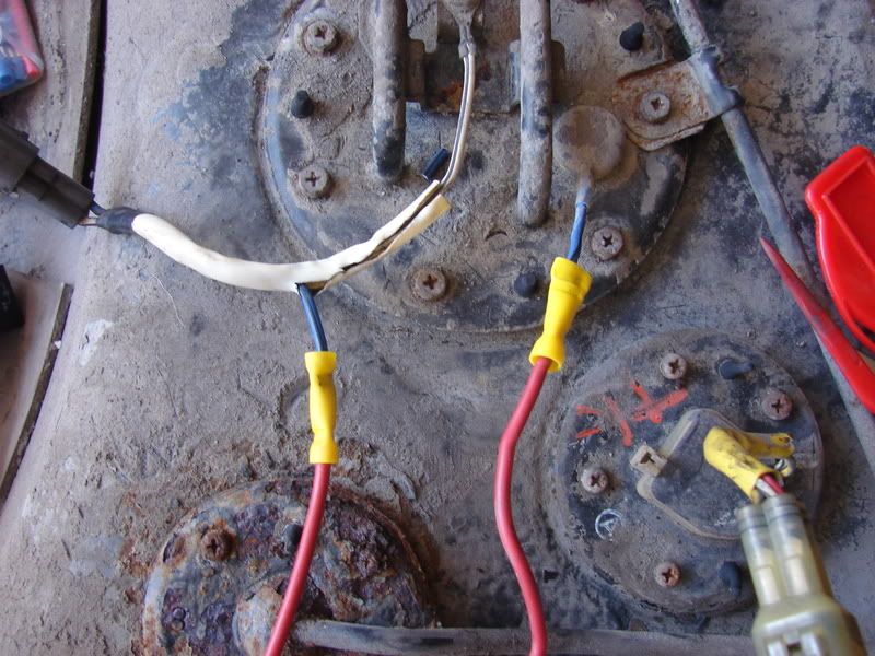
This is wires 1 and 4. You will cut the blue wire on top of the fuel pump bracket. Wire 1 will go to the piece of that blue wire that goes into the pump for power (wire on the right). Wire 4 connects to the other piece of the cut wire (wire on left). When your key is on, power comes from the harness, and runs through Wire 4 to the relay.
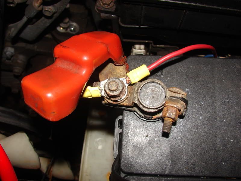
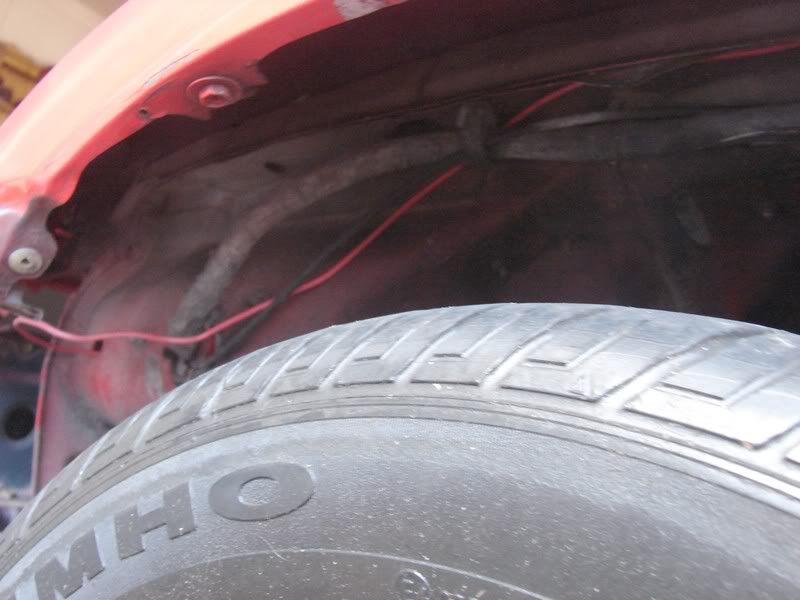
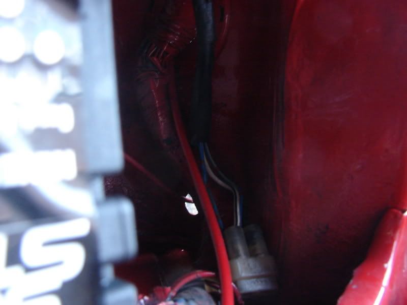
Wire 3 is the fused wire that you run from your battery to the relay. With my car still in the build stages, I had a real easy time with this wire. Double check now that your negative battery cable is taken off of the battery. I ran mine out of a small hole down in the corner on the negative side of the battery. Then once in the inner fender, I put my fuse into the wire. The inner fender is held in place with simple screws. Take it out, so you can run your wiring under there in the wiring clips, and into the car where the body wiring harness goes in. This is where you want to attach your wire to a coat hanger with Duct or Electrical Tape. It comes into the car near the fuse box or clutch pedal. (My mud flap is off, and the lower two bolts of my fender were out, so I could move my fender enough to see where I was going and find the hole. I don't think this is necessary, but it certainly seemed easier with it moved) Then I worked it over to the steering column, and into the area where the stereo is. You will remove the stereo bezel, stereo, console and lower rear seat. Run your wire (still on coat hanger) under the carpet from where it starts under the console to where it comes out at the tip of where the rear seat sits. Then run it under the rear seat top on the passenger side to the hatch area. I pushed my wire under the side interior plastic to where the trunk board support is, and around the corner unseen to the first bolt on that part. I will show several pictures here.
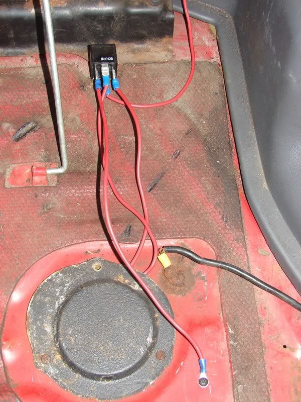
Wire 2 is a simple ground wire from the relay to the trunk floor. Do as I have been instructed to do, and sand the area that you plan to make your ground. I drilled a pilot hole, and used one of the little black screws that our cars are full of.
Wire at the battery
Through this hole

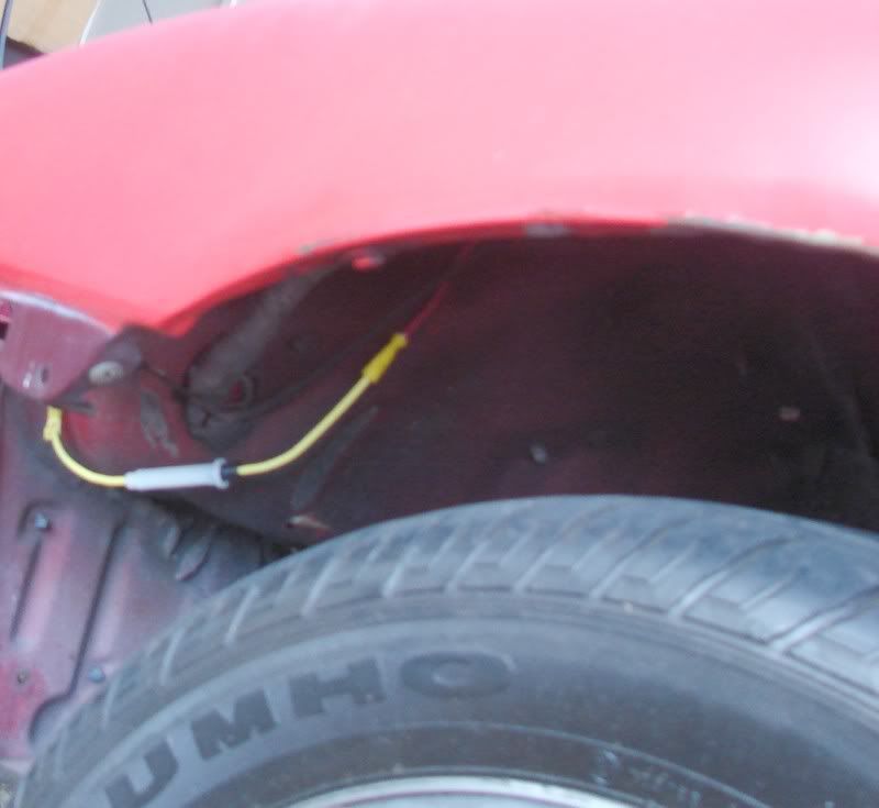
Here is my inline fuse that will be protected by the inner fender

Wire continuing through the fender tucked into the wire clips already under there. Picture taken before I put the fuse in.
Then through the hole into the car, coming out near clutch/fuse box , and across to the stereo area. Sorry no pictures of this more critical part!
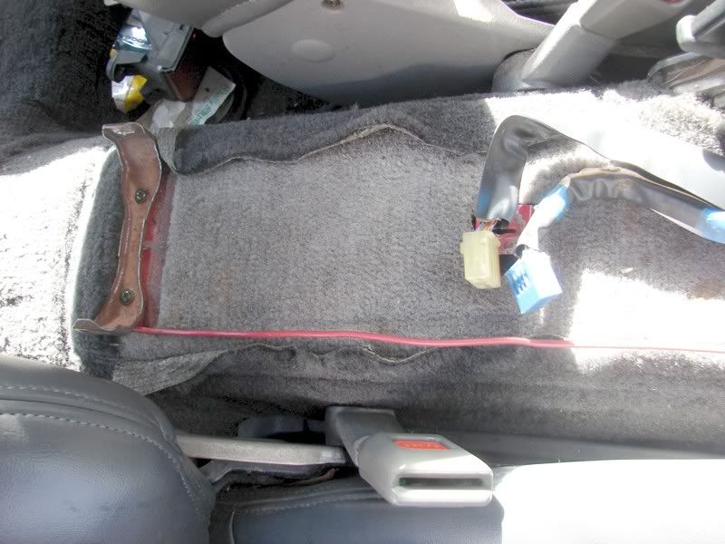
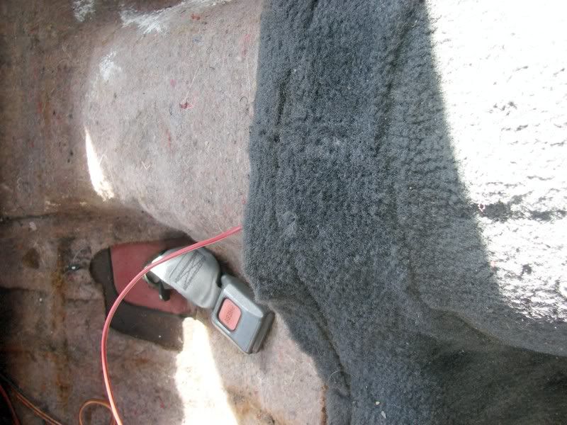
Now under the carpet and to the rear seat. My car has a second carpet glued on top of the original, and this was much more difficult than it should have been for me.


Then push it through to the hatch area and to the first bolt on the trunk board support. Here is how I mounted it. You can now see wire 2 in this pic. Be sure to sand off the paint.
Also, I have been warned that I might want to cut a hole in the access panel and use a gromment, rather than screwing the panel down on the wires. I still have to do that.

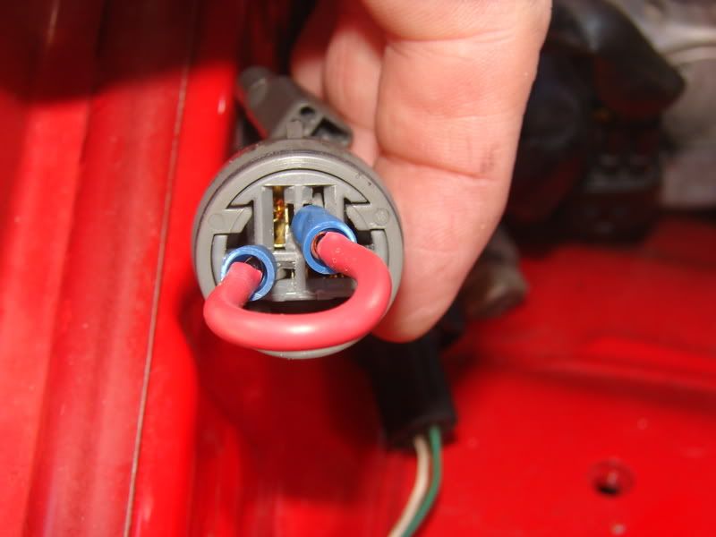
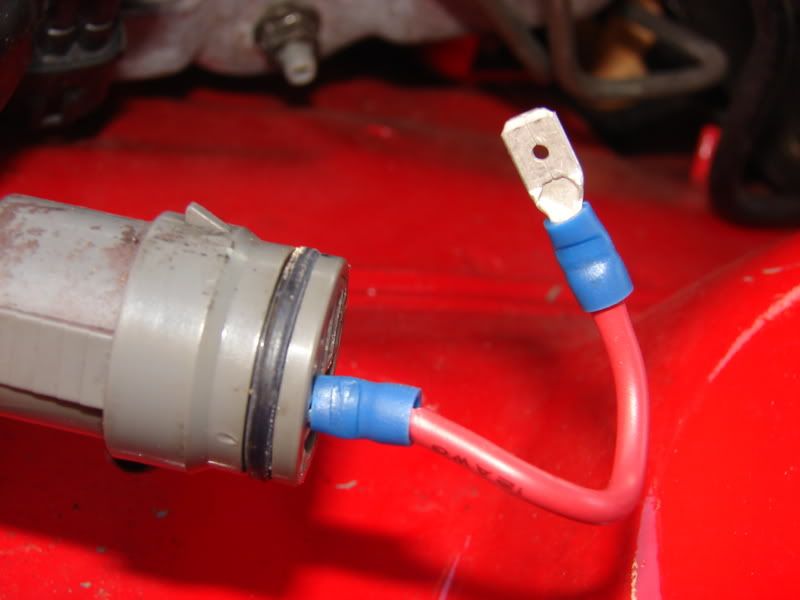
Now, the last step is to bypass the fuel pump relay and resistor. They are pretty much useless when upgrading the fuel system. Here's a picture of it done, and of the connector you need to use.

GOOD LUCK WITH YOUR INSTALL!
If you have any questions, please don't hesitate to ask. I will do my best to answer. I am no expert myself, and that's why I posted this tutorial to help those of you who have no idea what to do even after reading what to do. Sometimes a picture takes away all of the fear. I hope this helps. It's really not that hard of a swap.
Wiring diagram
[thumb]http://www.supramania.com/forums/attachment.php?attachmentid=25197&d=1223779257[/thumb]
Before we get started we must first see the parts in question, and what you are gonna need to do the job. I'm assuming that if you are going to do the job that you do have a jack, jackstands, and basic hand tools. Here you will see pictures of the Walbro pump kit, and most of the electrical pieces needed. I'm showing my sodering tool that I personally did not use. I used the butt connectors provided in the kit, and crimped them on.
Use a fuse holder like this, its water proof, uses a more common style of fuse, and all around is just better.
Next, we are going to prepare the car for the job by jacking the car from under the differential, and place jackstands in front of the rear wheels. I chocked the front wheel of the car to keep it from rolling backwards as the jack goes up. Then once the car was on the stands, I chocked it from rolling forward and falling off the stands with me under the car. Sorry no pictures of the chocks. You can use all types of things to do it with. A 2x4 or brick will work fine. I use a triangle rubber truck chock.
Now we're ready to pull the tank. You must first drain the tank, so try to plan this when you are low on fuel. I drained my little bit of fuel into a 5 gallon bucket. My car had been a shell fo so long I wouldn't dare re-use mine, but you can if you have fresh gas. All you need to drain the tank is a 3/8 extension on your ratchet. You then remove the round cover over the wires in your hatch. You only have to disconnect two plugs in there. Remove the 4 screws on the black plastic cover in your gas compartment, and remove the gas cap. Next you will disconnect the 3 fuel lines found on the back side of the tank. I used two crescent wrences, so I can't give you sizes here. The metal fuel line is said to give many people trouble, and may need to be replaced if you tear it up getting it loose. I used some PB Blaster on mine, and went and read my Walbro instructions while it worked it's magic. Mine came off without any trouble. Then you have two brackets with 2 12mm bolts each just inside the rear metal bumper, and 2 17mm nuts on the other end of the gas tank straps near the fuel lines. That's all you do to get the tank out. Here's pictures of everything mentioned there. Only one of the two brackets, and one of the two 17mm nuts are shown.
drain plug:
Hatch access panel (this rusty panel was pitched for a better one from my parts car)
Fuel pump wiring plugs
rear brakets (2 of these)
17mm nuts near fuel lines (2 of these)
Fuel Lines Just squeeze the clamps and move the back. Twist hose around in the line, and pull it free.
Remove gas cap and these 4 screws
Tank removed from the car with fill nozzle still attatched
Now that the tank is out, you are at the easy part, which is actually swapping out the fuel pump. I found this to be the easiest part of the three phases (removal/install of the tank, pump swap, wiring 12V mod) of this job. You are taking out the piece with the two hoses running from it. There are 8 screws (you can use an 8MM socket too). Once it is out, you cut the two wires leading from the pump to the top of the bracket you just removed. You will plug in the harness into the pump, and use the butt connectors provided in the kit to connect the wires to the that you cut. Pay attention to positive negative here! You can soder these wires if you would like, and even use shrink tubing to cover that if you wish. Replace the hose at the top with the new hose provided. Place the new pump into the bracket, and zip tie it to the bracket. You just installed your pump, put it back into the tank. I waited until I had my wires for my 12Vmod wer done there. I used a lot of wire, and cut it down later.
Pump bracket
old pump
close up to see wires you will cut
New pump installed
I will update again with 12V mod info and pics as soon as I get time this evening.
Now onto the wiring. I leaned heavily on this thread from Shaeff, as I am not very electrically inclined. Make sure you disconnect the negative battery cable before you proceed with this part.
http://www.supramania.com/forums/showthread.php?t=9417
That thread has a shot of a 12V relay, and a diagram of what wires to put where, with a list of what each wire is. He tells the story almost exactly as I did mine. I ran my relay to the bolt on the passenger side of the black part that supports the trunk board. Located there, it is raised just enough off of the floor, and just barely under the trunk board surface. Then I ran my wires underneath the trunkboard out of the way.I will show in pictures what Shaeff describes so well in his thread. He also uses this wonderful diagram.
http://www.supramania.com/forums/attachment.php?attachmentid=3420&d=1133647348
This is wires 1 and 4. You will cut the blue wire on top of the fuel pump bracket. Wire 1 will go to the piece of that blue wire that goes into the pump for power (wire on the right). Wire 4 connects to the other piece of the cut wire (wire on left). When your key is on, power comes from the harness, and runs through Wire 4 to the relay.
Wire 3 is the fused wire that you run from your battery to the relay. With my car still in the build stages, I had a real easy time with this wire. Double check now that your negative battery cable is taken off of the battery. I ran mine out of a small hole down in the corner on the negative side of the battery. Then once in the inner fender, I put my fuse into the wire. The inner fender is held in place with simple screws. Take it out, so you can run your wiring under there in the wiring clips, and into the car where the body wiring harness goes in. This is where you want to attach your wire to a coat hanger with Duct or Electrical Tape. It comes into the car near the fuse box or clutch pedal. (My mud flap is off, and the lower two bolts of my fender were out, so I could move my fender enough to see where I was going and find the hole. I don't think this is necessary, but it certainly seemed easier with it moved) Then I worked it over to the steering column, and into the area where the stereo is. You will remove the stereo bezel, stereo, console and lower rear seat. Run your wire (still on coat hanger) under the carpet from where it starts under the console to where it comes out at the tip of where the rear seat sits. Then run it under the rear seat top on the passenger side to the hatch area. I pushed my wire under the side interior plastic to where the trunk board support is, and around the corner unseen to the first bolt on that part. I will show several pictures here.
Wire 2 is a simple ground wire from the relay to the trunk floor. Do as I have been instructed to do, and sand the area that you plan to make your ground. I drilled a pilot hole, and used one of the little black screws that our cars are full of.
Wire at the battery
Through this hole
Here is my inline fuse that will be protected by the inner fender
Wire continuing through the fender tucked into the wire clips already under there. Picture taken before I put the fuse in.
Then through the hole into the car, coming out near clutch/fuse box , and across to the stereo area. Sorry no pictures of this more critical part!
Now under the carpet and to the rear seat. My car has a second carpet glued on top of the original, and this was much more difficult than it should have been for me.
Then push it through to the hatch area and to the first bolt on the trunk board support. Here is how I mounted it. You can now see wire 2 in this pic. Be sure to sand off the paint.
Also, I have been warned that I might want to cut a hole in the access panel and use a gromment, rather than screwing the panel down on the wires. I still have to do that.
Now, the last step is to bypass the fuel pump relay and resistor. They are pretty much useless when upgrading the fuel system. Here's a picture of it done, and of the connector you need to use.
GOOD LUCK WITH YOUR INSTALL!
If you have any questions, please don't hesitate to ask. I will do my best to answer. I am no expert myself, and that's why I posted this tutorial to help those of you who have no idea what to do even after reading what to do. Sometimes a picture takes away all of the fear. I hope this helps. It's really not that hard of a swap.
Wiring diagram
[thumb]http://www.supramania.com/forums/attachment.php?attachmentid=25197&d=1223779257[/thumb]


 ).
).