
So I took out my rear on the dyno so I had to do something I have wanted to do for a long time. I'm going to cover a complete rebuild of the differential including all bearings, seals, clutches and setup. I have lots of pictures but it was hard to get a picture of everything. I tried to take pictures of the hard to explain things so it would be easier for someone who never had one apart.
Want to send a big thanks to Joliroger4 and Piratetip for sharing there knowledge and experience. It was a big help with this project. Thanks guys!
First and foremost, Rebuilding a differential requires the use of a press. Presses are extremely dangerous. If you do not know how to use a press, are unfamiliar, or feel there not dangerous, PLEASE have a professional press your bearings/races onto the carrier/pinion/housing. Especially if you fall into that last category. They are not toys and you can be seriously hurt using one. Tens of thousands of pounds of force are stored in all of the parts of a press when pressing something and if something slips/breaks it can become a single or multiple deadly projectile(s) in an extremely short period of time. Especially on a smaller press (like mine) where you have to stand directly in front of it to operate it putting the object being pressed directly in front of your stomach/groin
To start out this is what you will need to rebuild this differential.
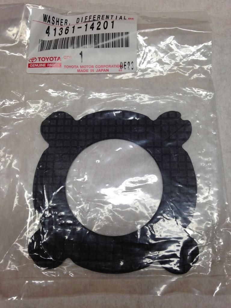
These are the parts I sourced from Toyota with the part numbers.
Two side carrier Bearings
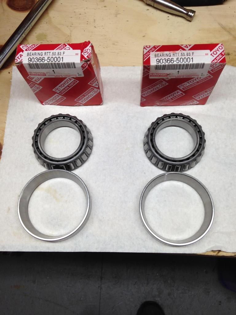
Pinion inner and outer bearings
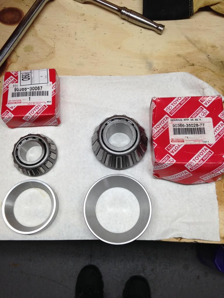
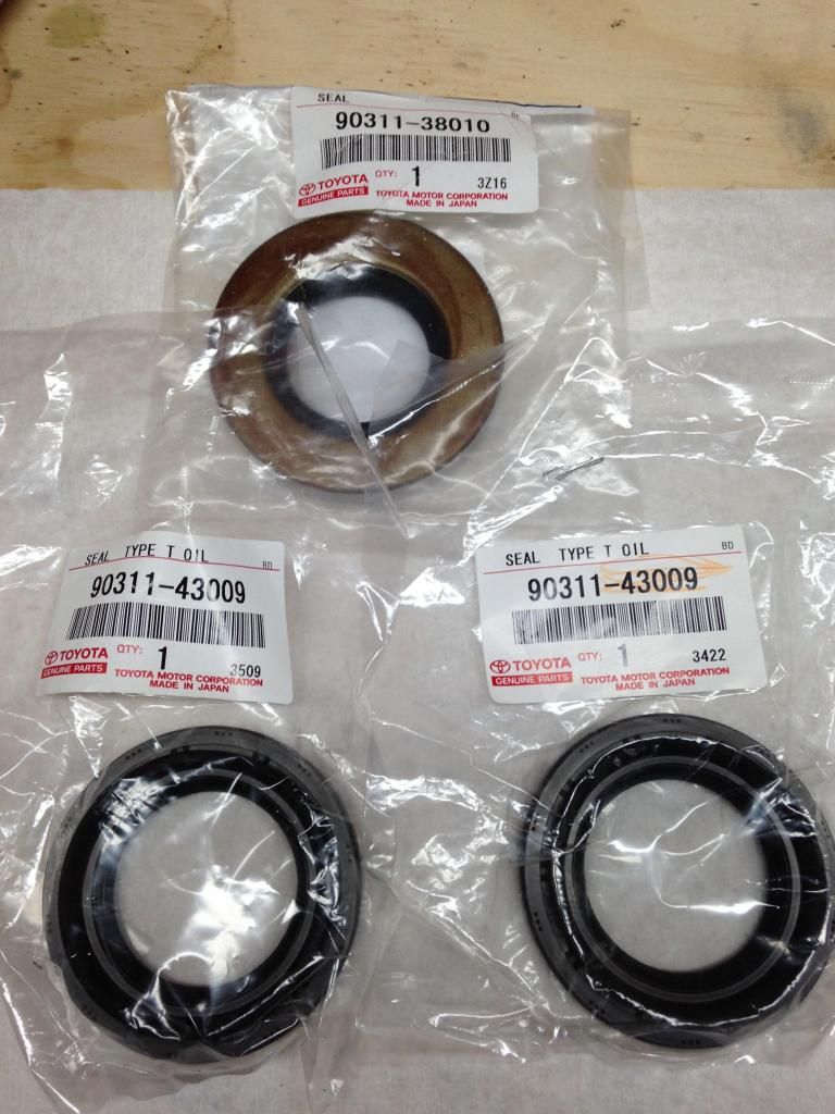
Pinion and axle stub seals
These are the "Clutch plates" as Toyota lists them. As you can see these are blank steel plates.
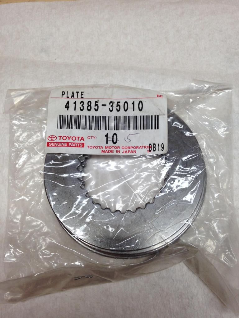
These are the "Thrust washers" as Toyota lists them, these are the plates with the clutch material on them.
I opted to use a solid spacer instead of using a crush sleeve on the pinion. I ordered the crush sleeve eliminator and the MAX GRIP LSD kit #1 from WEIR performance. The parts I got were high quality and it came with everything needed to install.
This is what it looks like.
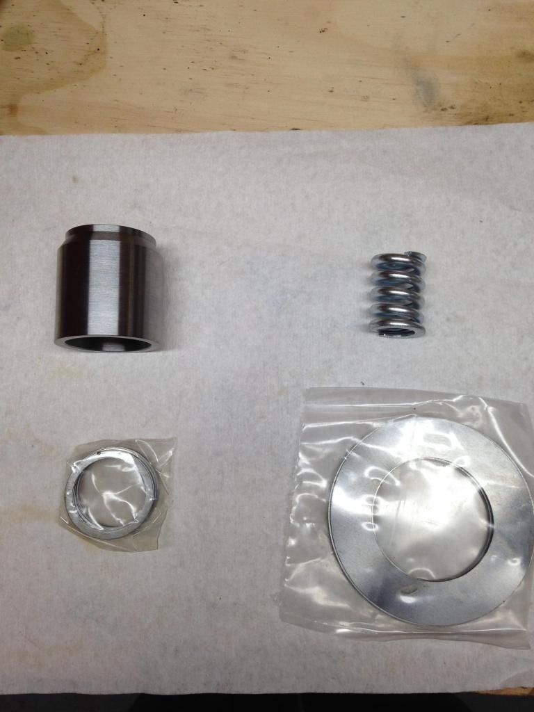
The MAX GRIP LSD kit is just a spring that goes INSIDE the stock spring that applies pressure to the outer spider gears and clutches.
OK enough of the parts on to the rebuild. Im only going to talk about tear down briefly as its a simple device and its not hard to get apart. There is just a few things you need to pay attention to before/as it comes apart.
Once the diff is removed from the car and the cover is taken off, your looking at the carrier/ring gear and the main bearing caps that hold the carrier into the housing. Before taking anything else off after the cover is off you need to wipe/clean the oil off the gears as much as you can so you can do a pattern check. I didn't have any gear marking compound so i used oil based paint.
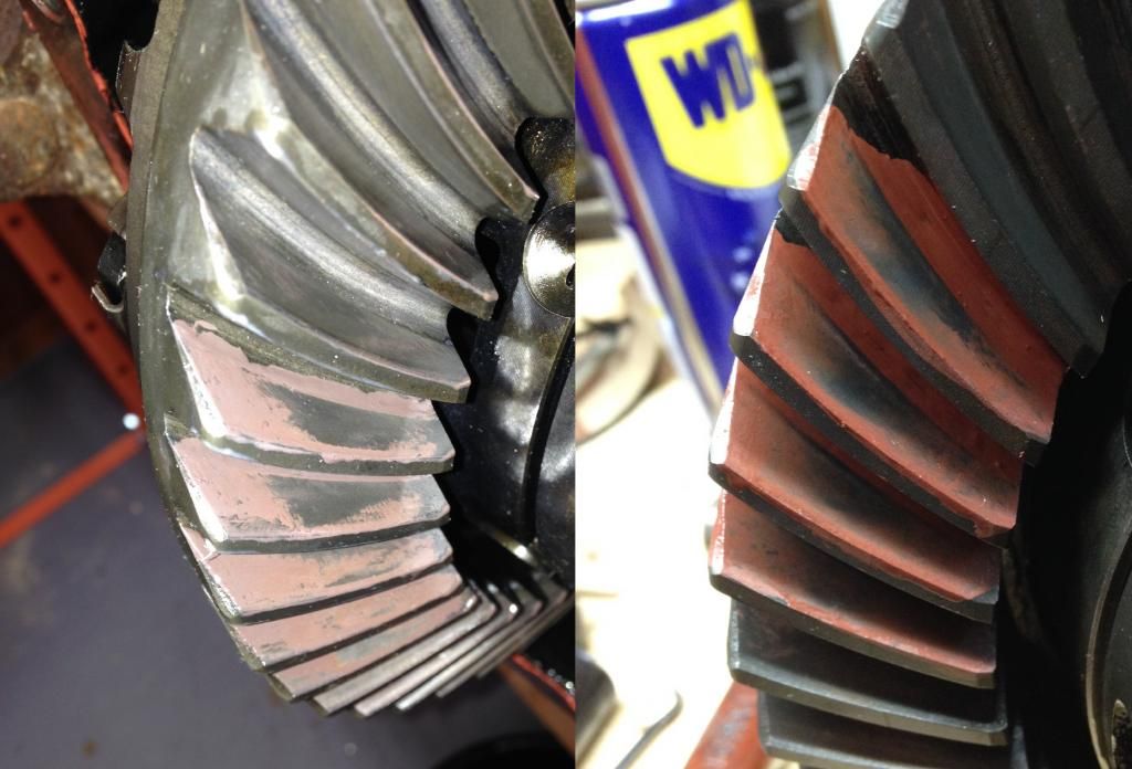
Paint a few teeth on the ring gear and roll the carrier around a few times making sure to put a resistance across the teeth to get a good reading. My pattern looked like this.
Drive side
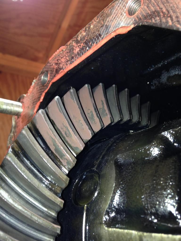
Coast side
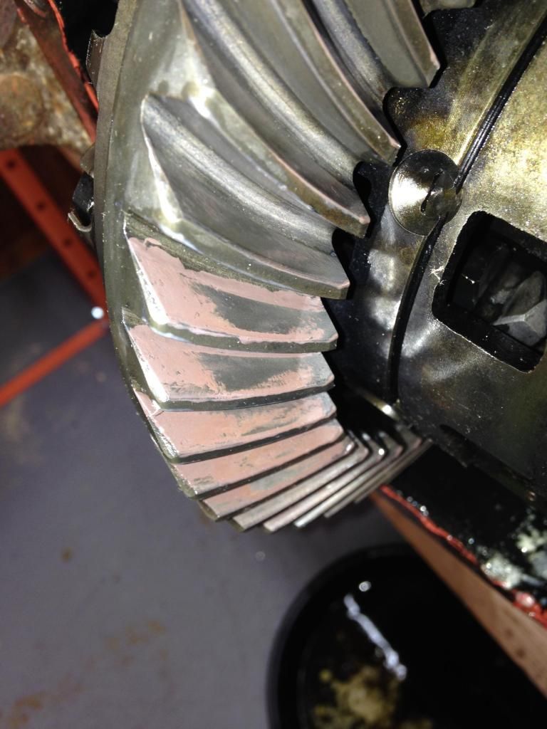
I would recommend doing each side individually and taking a picture of each side for comparison later after reassembly.
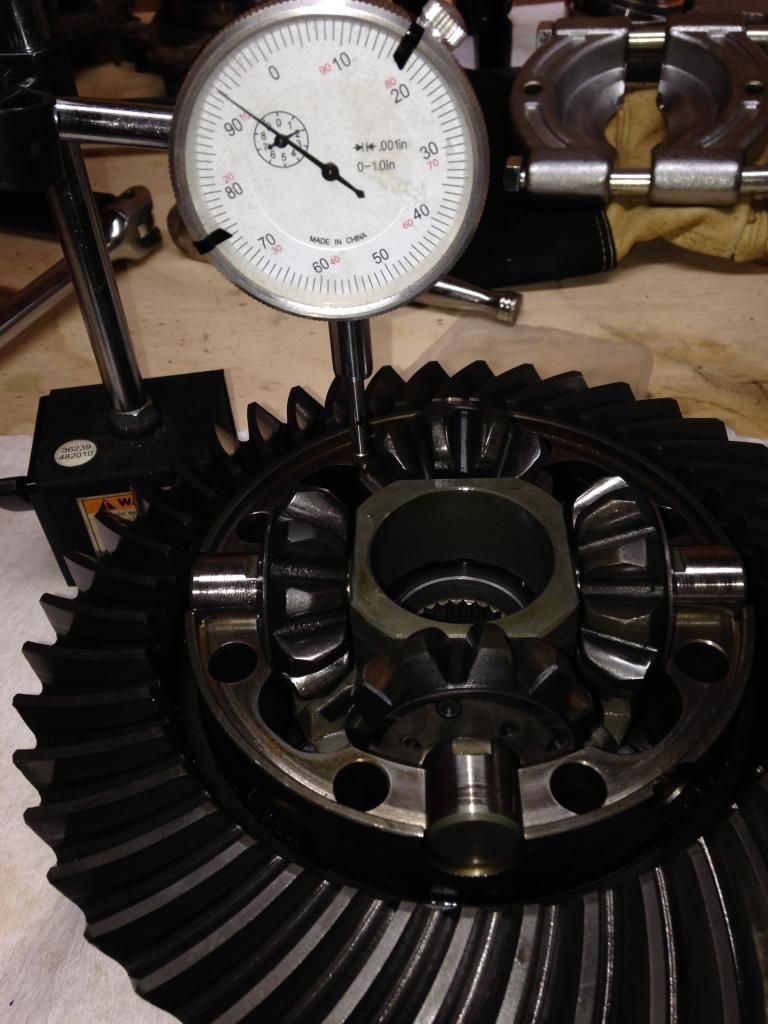
At this time it would be a good idea to get a backlash reading. I took one reading in four (4) places on the ring gear. My numbers were .009" - .0095" all around.
Now that you have this information you can continue disassembling. You'll need this information later on reassembly to ensure that the gears aren't noisy. It would also help to know if you have a serious problem now rather then later. First you'll need to remove the stub axles as they pass threw the housing and into the carrier. Use a slide hammer that attaches to the axle studs to pop them out. Mine didn't take much force to get them out. 2-3 good whacks should have them popped out. They are held in with a spring clip that sits in a groove around the splines of the axle stub.
Then remove the 4 bolts that hold the main bearing caps in and remove the bearing caps. Remember witch cap goes where, if you have to mark/label the caps then do so one at a time so you do not get them mixed up.
You will need to carefully pull out the carrier. Its wedged in there by the shims behind the carrier bearing races so its going to be tight. As you slide the carrier out the shims will come out with it. Make sure you catch these and remember witch side they come from. It would likely be obvious if there wrong when you try to put it back together because the backlash will be way off, but its good practice to keep track of what goes where as it comes apart.
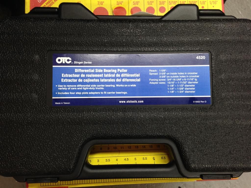
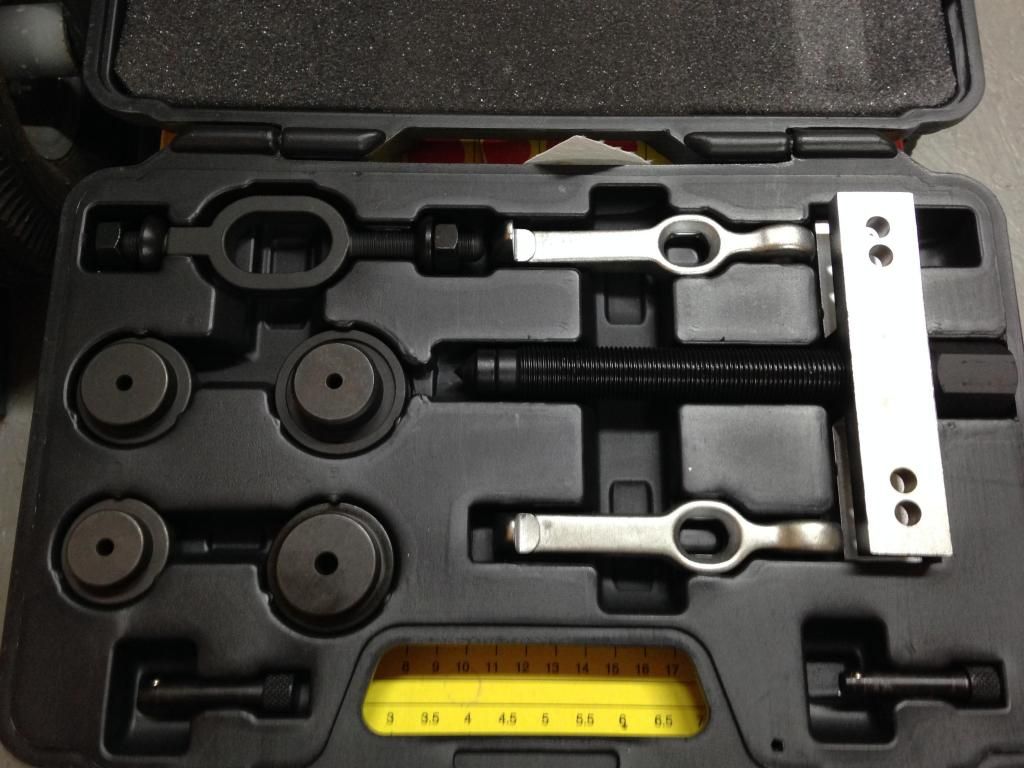
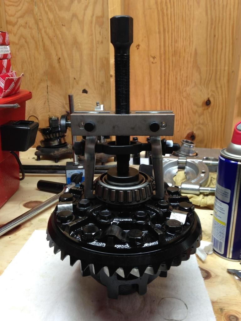
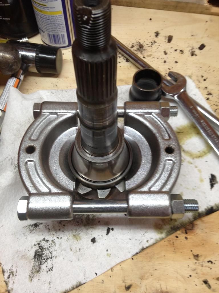
Once the carrier is out, put the rest of the housing assembly to the side, well get back to that later. IF your changing the carrier bearings I would remove the old ones now. I used an OTC tool that was about $75 dollars part number 4520. It removes them with ease. Here is a picture of the tool and how it is set up on the carrier to remove the bearings. It works awesome, i highly recommend it.
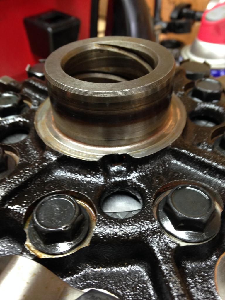
There are two indents cast into the carrier that allow the tool to grab underneath the bearing race. You cannot grab the bearing unless you put the arms in these notches, or you pull on the outer race. I wouldn't recommend pulling it by the outer race as it could snap and send roller bearing shrapnel everywhere. This picture shows the indents.
After you removed the bearings you need to split the carrier. You'll notice that one side has a ring of 8 bolts around it. I'm not talking about the ring gear bolts, there's another set that hold the two halves of the carrier together. The carrier should have a half way drilled dimple where the two halves meet as a match mark, but it wouldn't hurt to scribe another if you feel it necessary. You have to reassemble the halves back together in the same orientation as they came apart when your finished so this is important to make sure it is done right.
Remove the ring of bolts a little at a time to evenly split the carrier. The spring in the middle of the carrier will push the two halves apart. Once the bolts are removed you can carefully lift the half of the carrier up and over the clutches to reveal the inner workings of the carrier. It looks like this. This picture is missing two plates, the oil stuck it in the case.
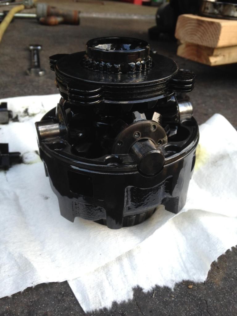
You can see the clutch arrangement on the spider gears. It is important to note how this is assembled to be sure that this goes back together the same way with the only difference being the new clutches/steels and the MAX GRIP LSD spring.
Now you grab the upper (in the picture) spider gear and lift it off the center gears and put it somewhere clean. Remove the clutches noting how they were put together. Grab the 4 pinion center cross support and remove that noting its orientation to the carrier.
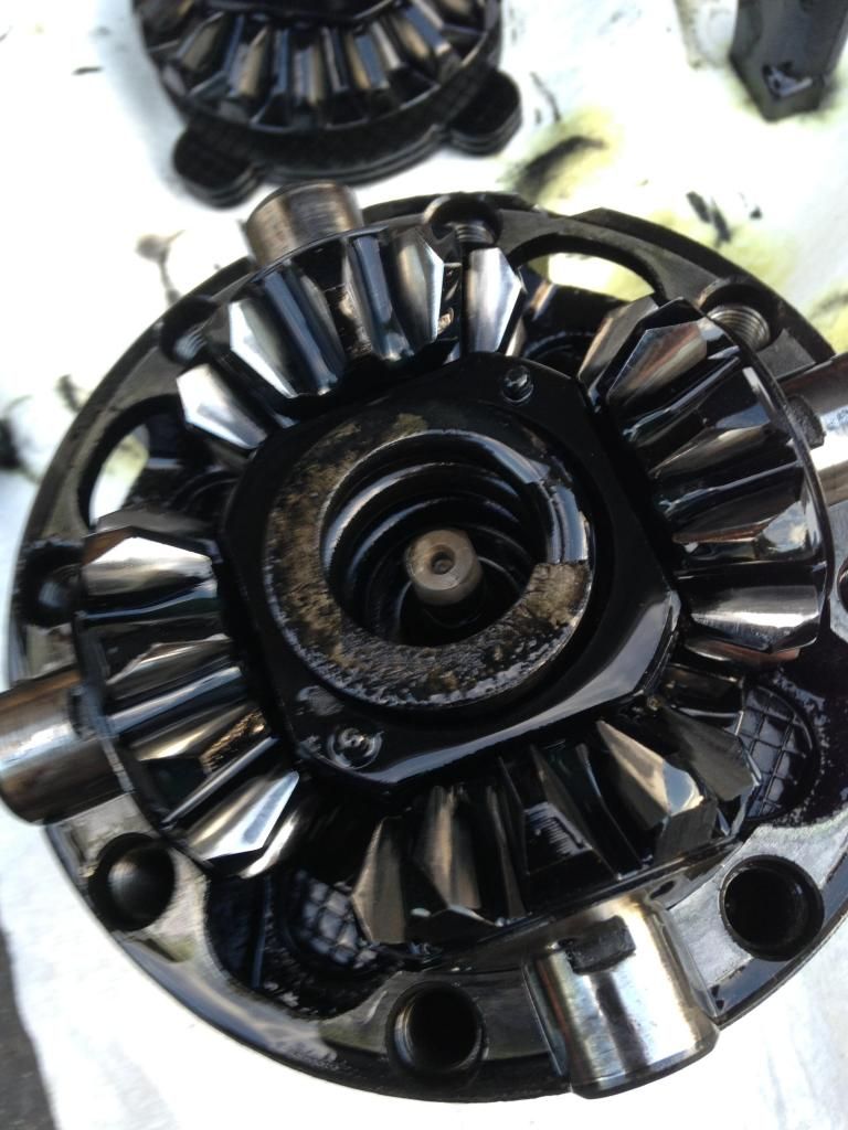
The cross support is different on the top and bottom. One side is smooth and the other side has two bumps that key into a plate so be sure to note its orientation or else it will not go back together properly. With the side spider gear removed you can see this in this picture. The post sticking up in the center of the spring is the smooth plate on the other side of the center support/spring. They key to each other with that post.
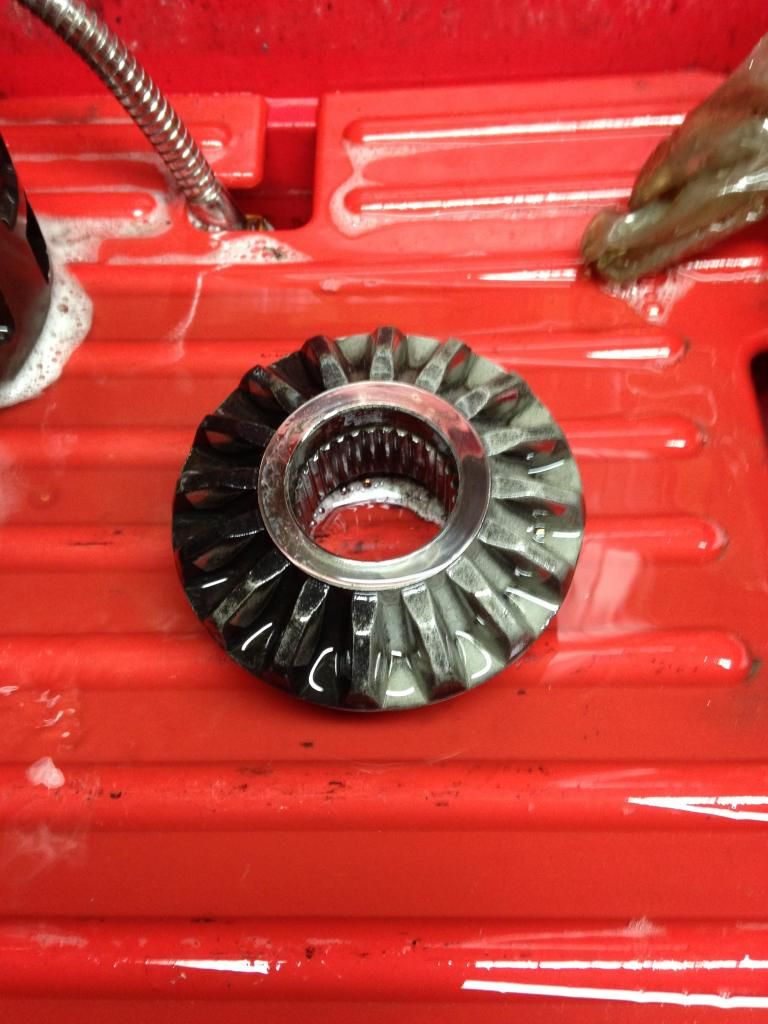
After removing all the spider gears/clutch packs from the carrier it is now bare. Thoroughly clean the carrier haves and spider gears and dry them good. I would shoot a light coat of WD40 or similar light oil on the parts because they are bare steel and will develop surface rust VERY quickly. These parts are likely to be very dirty as there isn't a ton of gear oil in these differentials and it typically doesn't get changed very often. Add in some worn clutch material and its a pretty slimy mess. This is the difference from dirty to clean on one of my spider gears. As you can see its quite the difference.
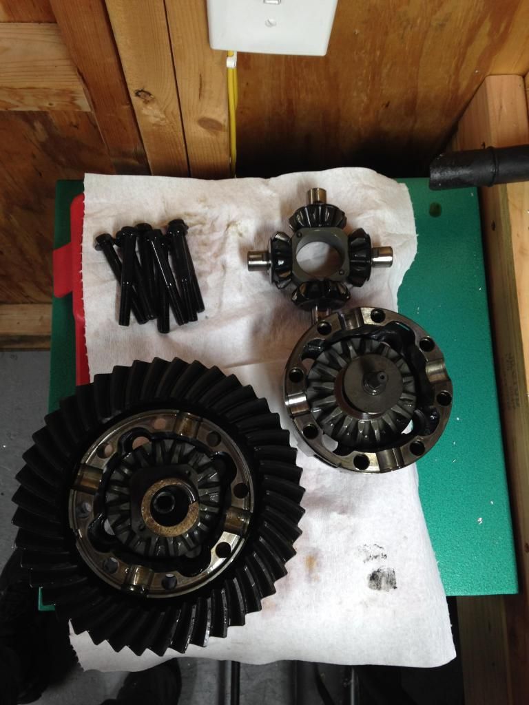
This is a view of all the parts clean without the clutches in the way. You can see the round smooth plate with the post and the square plate with the two holes and center tube in this picture.
OK! On to reassembly of the carrier!
First you need to grab your NEW "thrust washers" and "Clutch plates" and stack them onto the stub axle. Wipe the transport oil off of them with a clean towel before hand so there clean. There are 5 "thrust washers" and 4 "Clutch plates" on each side, in an alternating pattern. Here's the tricky part. The TSRM HERE says that you need to measure the depth of each side of the carrier and measure the height of the assembled clutches. Then subtract the measured clutch height from the case depth. Then subtract 16.15mm from that, to get your shim thickness. I tried this and then went with a slightly different approach.
I measured each of the housings and clutch packs as best i could with the tools i had as shown here.
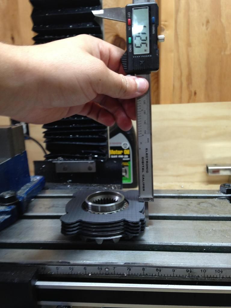
But i didn't like this method because i couldn't get (in my opinion) an accurate enough measurement for this. SO I measured the best I could and selected the indicated shim. I don't remember what it was off hand now. But what the TSRM says to do on the next page is to measure the backlash of the spider gear pinions.
What I did was a trial and error type arrangement where I swapped shims until I got the backlash of the spider gear pinions acceptable and stuck with that. The WEIR performance MAX GRIP kit comes with the necessary shims for this. The thicker the shims, the less backlash you will in the spider pinions. This is because those shims increase the installed height of the clutch pack, witch moves the outside spider gear closer to the pinions. I believe I ended up with .015" shims on both sides.
Once you get that shim sorted out the clutches on that side spider gear are now going to be used for that side. Do not use the same clutches/gear to adjust the shims on both sides.
After the shims are sorted out you can then begin to assemble the carrier halves back together. I found it easier to stack the clutches into the case and wiggle the spider gear into them rather then stack them on the spider gear and wiggle it into the case. Assemble one side at a time.
Make sure you put a good coating of gear oil on all the parts, especially the clutches and plates, you don't want them to be dry.
Stack the clutches and spider gear into the case half that the bolts thread into. Then put the plate with the post/tube depending on how yours came apart on the face of the spider gear. Next put the cross support.
My differential had the thicker of the factory LSD springs (pre 89) so the MAX GRIP spring was a tight fit inside of it but it did fit. I used a vice to carefully press the MAX GRIP spring into the center of the stock spring.
Place the spring threw the center of the pinion cross support and key the matching plate into the tube/post. Then you need to put the spider gear with the clutches stacked on it on top of that and gently slide the case over the top of it.
I struggled the most with the assembling the case halves together. THE SPIDER GEARS MUST LINE UP When you attempt to bolt the sides of the carrier together!
If you do not have the spider gears lined up perfectly, the spring pressure on the clutches will prevent the gears from turning and meshing properly, and you will be likely to crack the teeth of gears. If your tightening the bolts and it gets tight before the cases meet, stop and adjust the gears. It took me 5-7 tries to get them together smoothly.
When you put the case over the top, before tightening the bolts you can see the spider gear thru one of the windows. Ensure it is lined up the best you can BEFORE tightening the bolts.
AGAIN WARNING: PRESSES ARE EXTREMELY DANGEROUS! DO NOT ATTEMPT TO PRESS ANYTHING IF YOUR NOT SURE WHAT YOU ARE DOING!
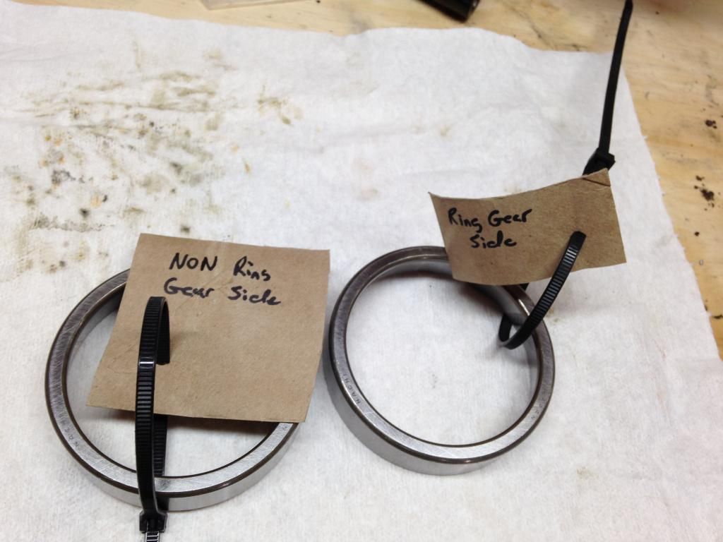
Once you get the carrier bolted together you need to press the new carrier bearings on if you removed them previously. This is most easily done with a press and using one of the old inner races. When you remove the new carrier bearings from the box, mark the outer races with which side the bearing is going to be on. You want to keep the bearing and the race as a matched set. I'm not sure if it would be a problem to mix them as there both brand new, but I'm not willing to take that chance so I labeled them and put the bearing on the corresponding side. These bearings go on pretty easily with a 12 ton press but if your not quite sure what your doing, have a professional press the bearings for you. PRESSES ARE EXTREMELY DANGEROUS.
I had a near 3 inch round chunk of 3/4" aluminum from when I made my throttle body flange so I used that on top of the old race to press the new bearing on.
The only thing about using the old race is that it will VERY SLIGHTLY get pressed on in the process. With a very delicate tap of a light hammer it pops right off. It only gets pressed on about .010-.015" so it does come back off very easily. This is the lip is presses on to.
This video shows how easy it is to get off.
[video=youtube;qgee45hjZ5k]https://www.youtube.com/watch?v=qgee45hjZ5k[/video]
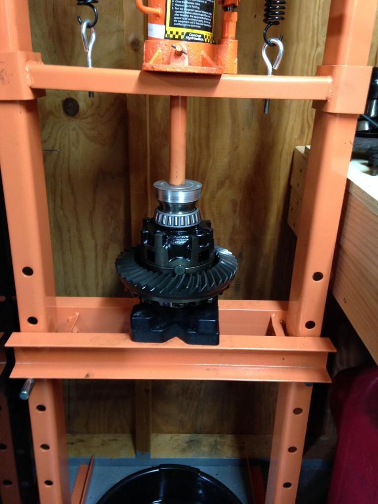
After you have pressed the bearings on the carrier is now complete. That was the most work. The pinion can be a pain to set up with the crush sleeve eliminator but its ONE thing you need to do. So set the carrier aside somewhere safe and clean, put some gear lube on the side bearings and bring out the housing with the pinion.
If your going to change the pinion bearings you need to take everything apart. The pinion nut IIRC (did this about a month ago) is 30mm. I made a tool from a piece of 3/8 rod and some scrap angle iron to hold the drive shaft flange while i tightened/loosened the nut. As you can see i took this picture after using it a few times so it got a little bent, but it held just fine.
After carefully knocking the stake out of the pinion nut use something to hold the drive shaft flange (besides a screwdriver, I herd it can warp the flange) and back off the nut. The first differential I took apart (the old worn out one) the pinion slid right out after loosening the nut. The second diff (The new good one) I had to press it out.
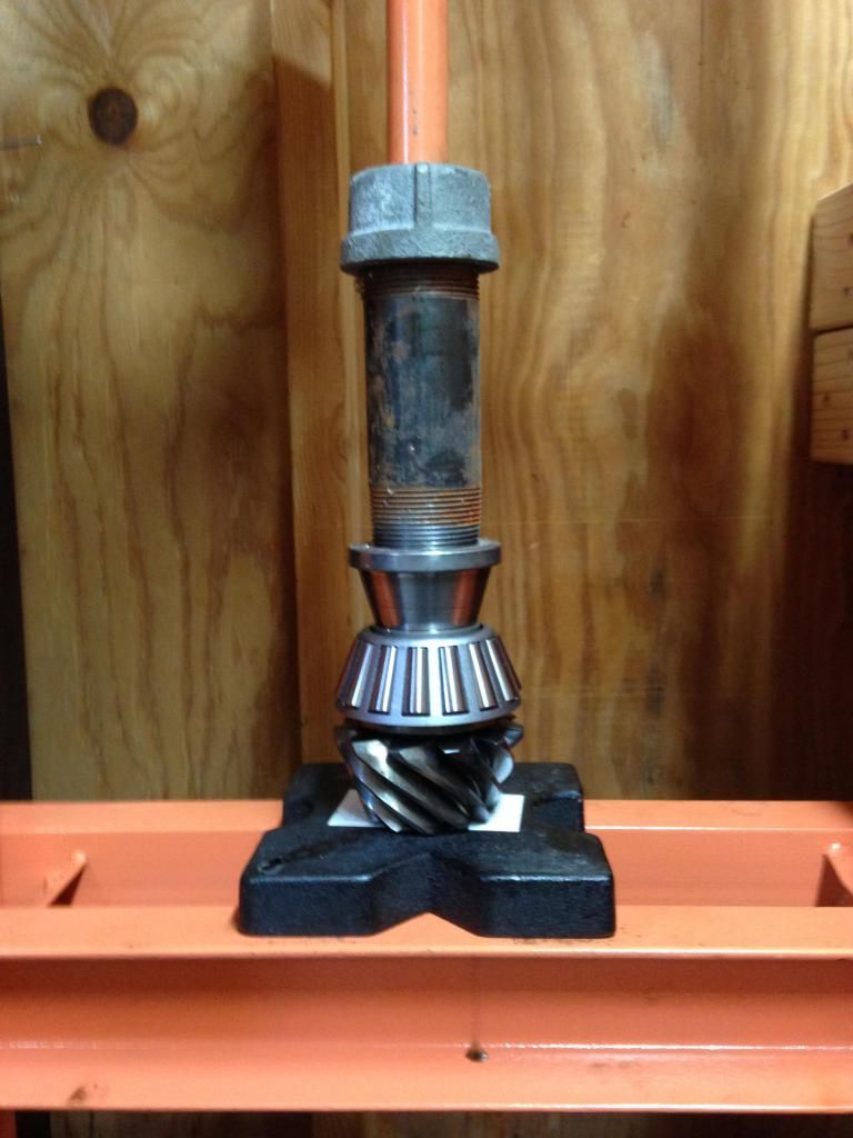
I pressed it out on my press carefully and put a rag beneath the pinion in case it slid out it wouldn't bash down on the metal bed of the press. Once it started moving it moved easily and i was about to put my and up underneath and grab it so it didn't fall.
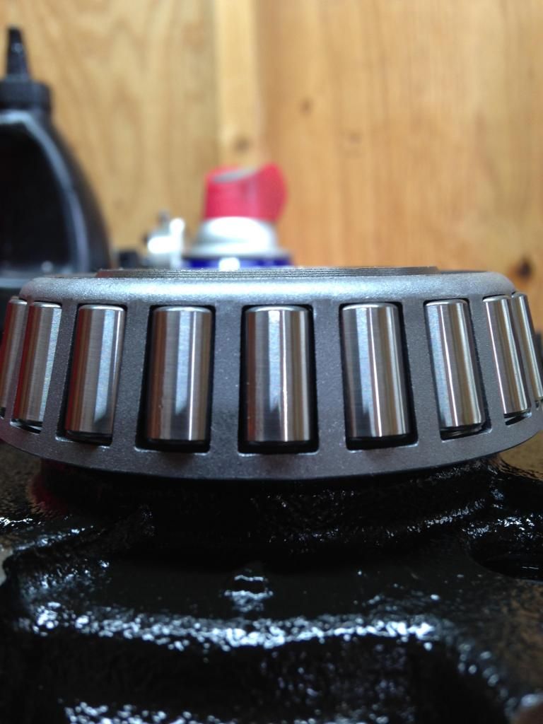
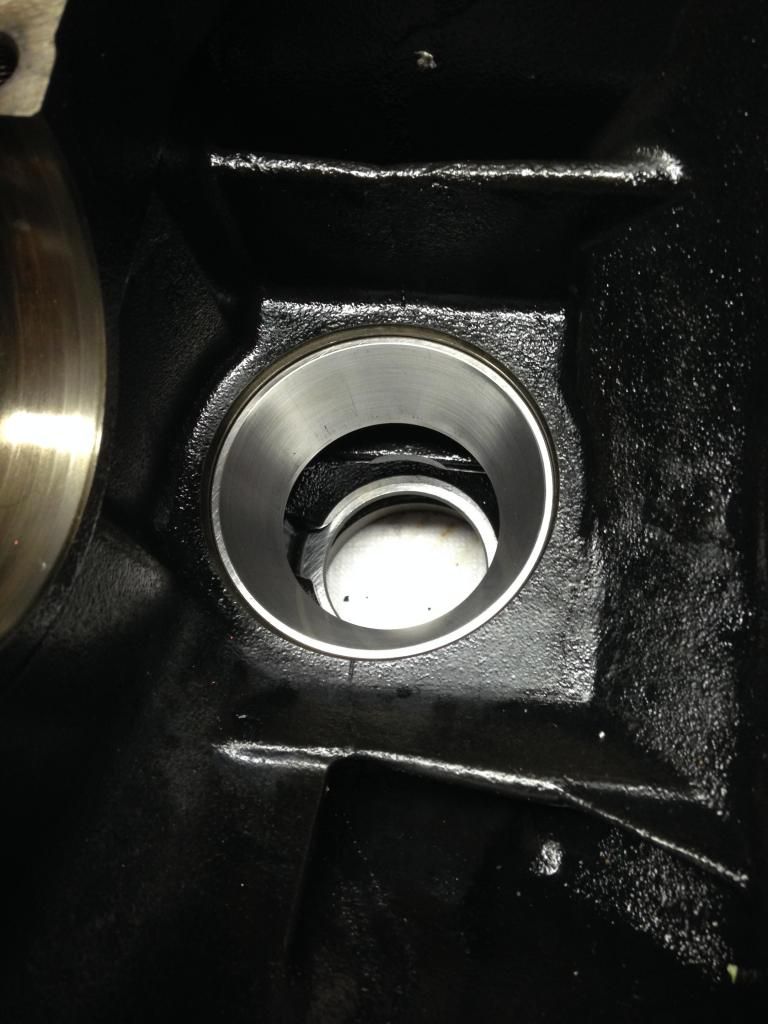
Once the pinion was out the outer bearing is just sitting in the outer race. Remove that bearing from the housing and observe the races and the pinion gear to make sure nothing jumps out at you as being broken/worn as this is the first time you can really actually see them. This is what you get when you press the pinion out.
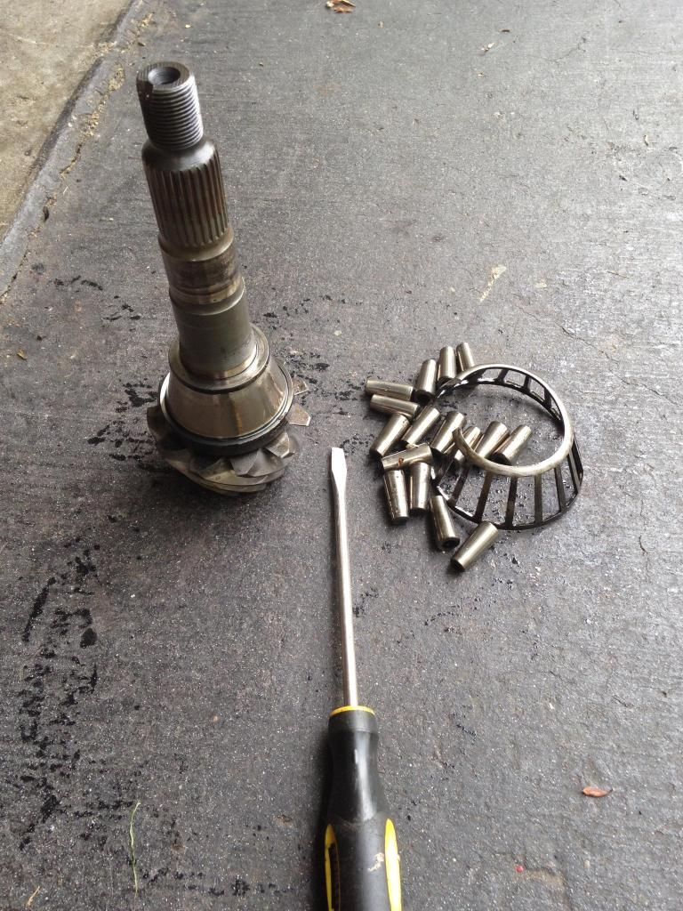
On to the hardest part of the rebuild. Removing that G*D D**M inner pinion bearing is a real BI*CH. I cut the bearing cage off so that i could get under the outer race with a bearing separator plate. I had to get longer bolts because the studs that came with the plate kit were not long enough for it to grab around the bearing. A larger plate would likely have worked better but i made use with what i had at the time.
AGAIN WARNING: PRESSES ARE EXTREMELY DANGEROUS! DO NOT ATTEMPT TO PRESS ANYTHING IF YOUR NOT SURE WHAT YOU ARE DOING!
I put the bearing separator plate on the two press plates my press came with a had to REALLY pull on the handle to get it to break free. I have a Harbor Freight 12 ton press. Its not bad, but for this bearing, it barely had enough. This bearing is REALLY REALLY on there. You cant see in the picture but I have my press to the side of my tool box. I was using my toolbox for cover as i was pressing this bearing off because i was legitimately concerned that metal might go flying.
When this bearing moves, You will know it. It will sound like a gunshot and you will likely need a change of drawers. I used an acetylene torch to heat the bearing race up moderately (not glowing red, just hot, like 2-300 degrees) and then slapped it in the press. I didn't think it was going to move until, BANG! It moved. After the initial BANG it moved much easier. But I cannot stress enough how hard it was to remove this bearing race from the pinion. This is the reason I don't have a picture of how I had it set up in the press is because it was that much of a Bi*ch to get off.
Anywho, once that bearing race is off take notice of the shim that was under the old bearing race. This MUST be installed under the new bearing when it is pressed on or you will be tearing this all back apart. It goes on a certain way so make sure you get it right so you don't have to pull the brand new bearing you just put on.
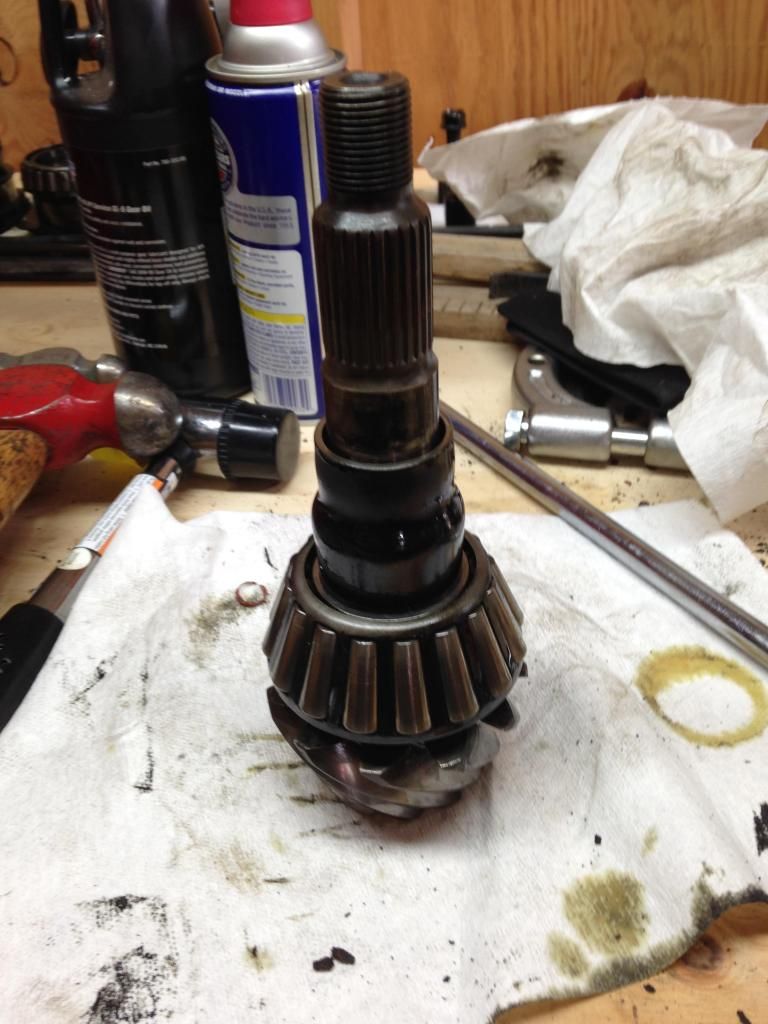
You now have a bare pinion ready for the new bearings. I pressed the new pinion inner bearing on using the old inner race. The trick to using the old inner race was putting the old race on my mill and using a boring head to take a few thousandths off the inner surface so it wouldn't get pressed onto the pinion like the carrier bearing race did. If you don't open up the inner diameter it will get pressed on and will likely be a bi*ch to get off.
I bored it out on my mill until it easily slid over the bearing surface of the pinion. Then I used a piece of steel tube with an iron end cap over the pinion to press the new bearing on. Looking back, I think the cast iron cap may have been a bad idea considering how brittle anything cast is. Being it was iron it would have been a bad thing if it became a grenade. Learn from my almost mistake and use something more solid.
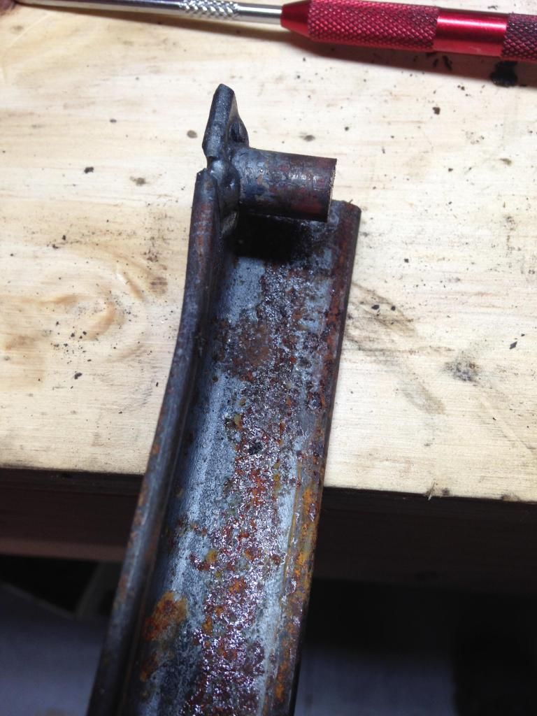
Once the inner bearing is on, your attention needs to be turned to the housing and getting the old bearing races/seals out and the new ones pressed in. I used a hammer and a long pry bar to hammer out the old pinion/axle seals and I made a tool for pressing the old bearing races out. Used some scrap angle steel and some scrap flat stock steel. I welded them together to make a triangle that would use its shape to be strong. Yea, I'm kind of an engineer, No big deal. :biglaugh:
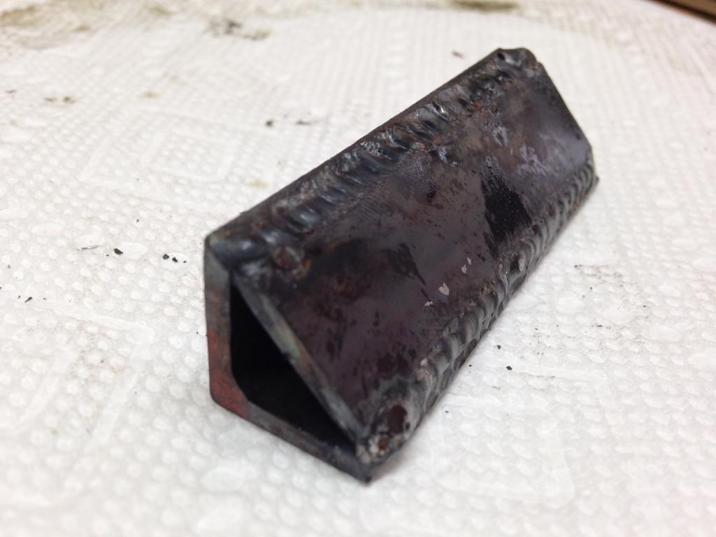
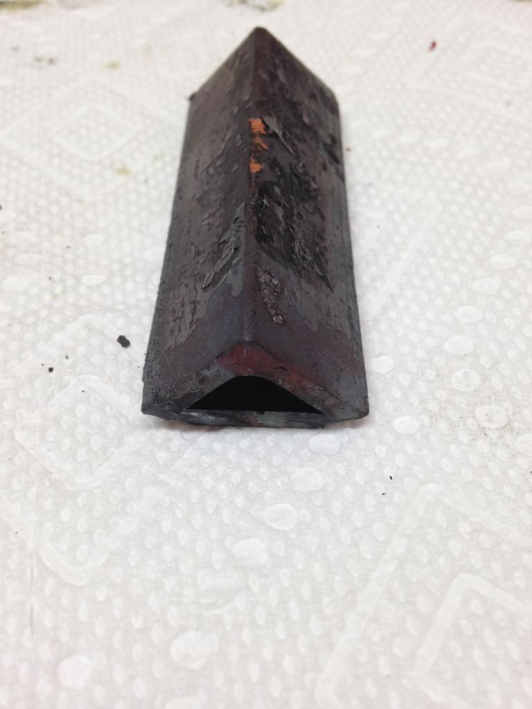
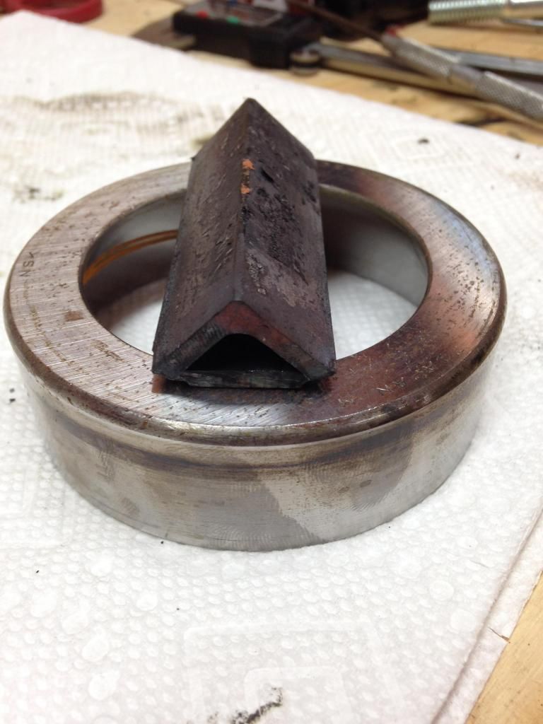
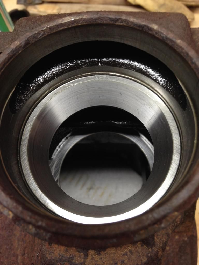
I dropped that down onto the backside of the bearing race and used the press to push down on the middle of it to press them out. Once they were out Pressing the new ones in was pretty much the same. Put the new one in the hole, put the old one on top of it upside down and use the same tool to press them in. Had a slight problem with the outer pinion race. The old race pressed itself into the housing. I used the same tool on the face of it to pop it back out. Hope that made sense, if it happens to you you'll understand what i meant by that.
Once the new pinion races are in its time to set up the crush sleeve eliminator. Don't install the seal until you get the pinion preload squared away. Start out by measuring the old crush sleeve. Its length should give you a good idea where to start. Go .002 bigger to give the bearings a little extra clearance and see what you get. If you tighten the nut and the pinion spins easily, its too thick and shim size needs to be decreased. I believe I ended up being around .020" to get mine right. The shim size is right when the pinion has 9-14 IN/LBS of preload when measured with an IN/LB beam style torque wrench. Don't forget to give the bearings a healthy coating of gear oil before installing the pinion in the case.
HERE'S A TIP, The pinion nut is apparently supposed to be a one time use nut, so get the preload right and assemble it for the final time with the old nut. Then remove the old nut, install the pinion seal and new nut, tighten it to the final torque and stake it. Before final assembly with the new nut, take a hammer and tap the housing around where the pinion bearings are. This will ensure the rollers are seated fully and will change you preload numbers. If you forget to do this, it will happen as your driving. You will likely loose all pinion preload and will be doing this job all over again. Take the time to make sure everything is right the first time.
The factory torque spec for the nut is 134FT/LBS adding 9FT/LBS at a time to achieve proper preload with a crush sleeve without going over 250Ft/Lbs. Since i wasn't using the crush sleeve my range for torque was 134-250Ft/Lbs. I went with 150Ft/Lbs.
Your pinion is now squared away ready to roll unless you have a terrible pattern from the new bearings throwing the pinion depth off.
The only thing left to do now, is to install the carrier into the housing and check backlash and gear mesh. Throw a good coating of gear oil on the carrier bearings, grab the new carrier races and place them over the matching bearings, put the original shims back on the outside of the race they originally came out from and gently begin to push the carrier into the housing. Its going to be a tight fit just like when it came out so be prepared to used a rubber mallet to gently tap it into place. Make sure the shims slide all the way in, they like to stick out and pretend there all the way in but there not. If you look in the holes in the case where the stub axles go you can see if there all the way in or not.
To make sure there seated you can use a flat blade screw driver, or a small punch and hammer to GENTLY tap them into place. If they don't move and it sounds real solid when you tap them STOP. Don't beat the hell out of them with the hammer.
Pop on the bearing caps and snug the bolts and make sure the whole assembly turns. If its locked up, Something is wrong, maybe the carrier shims are swapped. As long as all the shims are in the right place it should be good.
If it turns smooth and doesn't sound noisy and nothing is obviously wrong then torque the carrier bearing cap bolts to spec. Make sure at this point that everything still turns smooth. If it does, grab your dial indicator and take the same 4 backlash readings that you took before and compare the results. Don't forget to take a hammer and lightly tap the bearing caps to make sure the rollers are all seated fully.
My first backlash numbers were .009-.0095, after the rebuild they changed to .006-.0065. After I checked the backlash I checked the gear mesh again to make sure the pattern had not changed. Here's a comparison of the before and after.
Drive side
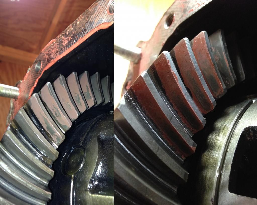
Coast Side
If your backlash looks good, and your gear mesh looks good the only thing left to check is the TOTAL preload of the differential assembly. Its a pretty specific procedure but its not very difficult. You need to put your In/Lb torque wrench on the pinion nut, apply pressure to the wrench until the pinion takes up the backlash slack. Now the pinion gear is firmly contacting the ring gear. As you apply pressure to the torque wrench it is trying to now turn the whole assembly as one. As you apply more and more pressure it will eventually break the start torque and begin to turn. It is that initial start torque of the whole assembly you need to measure. The TOTAL preload should be 3.5-5.2 In/Lbs more then the pinion preload alone.
If that all checks out the only thing left to do it install the side axle oil seals, rear cover and reinstall back into the car.
Overall I had a small shift in the pattern but its not enough to worry me and I have installed and ran this diff for about a month now at 520Whp with no noise or issues. Other things i noticed was a difference between a pre89 and post89 magnetic drain plugs. The 89+ is on the left. Its the same size thread for the drain plug and the fill plug so I put the pre89 magnetic plug in the fill hole so I have two magnetic plugs for extra protection.
I also originally filled this differential up with Carquest brand 75-90 gear oil. On the bottle is said "LSD top off only", so I figured there was no additive. When I first drove it around I noticed ZERO popping/creaking normally associated with a fresh rear and no LSD additive. After some reading on the forums and saw REDLINE 75-90NS (No LS additive) was recommended by a few people. I ordered some to give it a try. After putting the REDLINE in within minutes the rear was popping/creaking pretty fierce. I was a little nervous because it sounded like the rear sub frame was falling out, but i was very happy at the same time to know that the limited slip is much more limited now. I have added some REDLINE Additive since. They recommend a 4% solution. I added a little at a time and have reduced the popping/creaking a lot. It is still a little creaky but its MUCH better then it was before. I don't want to add anymore because i want the strong effect of the limited slip as my car makes decent power and the more traction i can get the better. I believe i ended up adding about 25 Milliliters with a small plastic syringe. I feel that I am at a good balance between traction and clutch life.
I'm sure there is a couple things I missed, or could have done better or different. This was how I did it and it worked for me. I also re-read this so many times to try to catch all of my horrible spelling and terrible grammar my head is spinning. Hope this helps someone. Feel free to ask questions/comments.
-Dan
Want to send a big thanks to Joliroger4 and Piratetip for sharing there knowledge and experience. It was a big help with this project. Thanks guys!
First and foremost, Rebuilding a differential requires the use of a press. Presses are extremely dangerous. If you do not know how to use a press, are unfamiliar, or feel there not dangerous, PLEASE have a professional press your bearings/races onto the carrier/pinion/housing. Especially if you fall into that last category. They are not toys and you can be seriously hurt using one. Tens of thousands of pounds of force are stored in all of the parts of a press when pressing something and if something slips/breaks it can become a single or multiple deadly projectile(s) in an extremely short period of time. Especially on a smaller press (like mine) where you have to stand directly in front of it to operate it putting the object being pressed directly in front of your stomach/groin
To start out this is what you will need to rebuild this differential.
These are the parts I sourced from Toyota with the part numbers.
Two side carrier Bearings
Pinion inner and outer bearings
Pinion and axle stub seals
These are the "Clutch plates" as Toyota lists them. As you can see these are blank steel plates.
These are the "Thrust washers" as Toyota lists them, these are the plates with the clutch material on them.
I opted to use a solid spacer instead of using a crush sleeve on the pinion. I ordered the crush sleeve eliminator and the MAX GRIP LSD kit #1 from WEIR performance. The parts I got were high quality and it came with everything needed to install.
This is what it looks like.
The MAX GRIP LSD kit is just a spring that goes INSIDE the stock spring that applies pressure to the outer spider gears and clutches.
OK enough of the parts on to the rebuild. Im only going to talk about tear down briefly as its a simple device and its not hard to get apart. There is just a few things you need to pay attention to before/as it comes apart.
Once the diff is removed from the car and the cover is taken off, your looking at the carrier/ring gear and the main bearing caps that hold the carrier into the housing. Before taking anything else off after the cover is off you need to wipe/clean the oil off the gears as much as you can so you can do a pattern check. I didn't have any gear marking compound so i used oil based paint.
Paint a few teeth on the ring gear and roll the carrier around a few times making sure to put a resistance across the teeth to get a good reading. My pattern looked like this.
Drive side
Coast side
I would recommend doing each side individually and taking a picture of each side for comparison later after reassembly.
At this time it would be a good idea to get a backlash reading. I took one reading in four (4) places on the ring gear. My numbers were .009" - .0095" all around.
Now that you have this information you can continue disassembling. You'll need this information later on reassembly to ensure that the gears aren't noisy. It would also help to know if you have a serious problem now rather then later. First you'll need to remove the stub axles as they pass threw the housing and into the carrier. Use a slide hammer that attaches to the axle studs to pop them out. Mine didn't take much force to get them out. 2-3 good whacks should have them popped out. They are held in with a spring clip that sits in a groove around the splines of the axle stub.
Then remove the 4 bolts that hold the main bearing caps in and remove the bearing caps. Remember witch cap goes where, if you have to mark/label the caps then do so one at a time so you do not get them mixed up.
You will need to carefully pull out the carrier. Its wedged in there by the shims behind the carrier bearing races so its going to be tight. As you slide the carrier out the shims will come out with it. Make sure you catch these and remember witch side they come from. It would likely be obvious if there wrong when you try to put it back together because the backlash will be way off, but its good practice to keep track of what goes where as it comes apart.
Once the carrier is out, put the rest of the housing assembly to the side, well get back to that later. IF your changing the carrier bearings I would remove the old ones now. I used an OTC tool that was about $75 dollars part number 4520. It removes them with ease. Here is a picture of the tool and how it is set up on the carrier to remove the bearings. It works awesome, i highly recommend it.
There are two indents cast into the carrier that allow the tool to grab underneath the bearing race. You cannot grab the bearing unless you put the arms in these notches, or you pull on the outer race. I wouldn't recommend pulling it by the outer race as it could snap and send roller bearing shrapnel everywhere. This picture shows the indents.
After you removed the bearings you need to split the carrier. You'll notice that one side has a ring of 8 bolts around it. I'm not talking about the ring gear bolts, there's another set that hold the two halves of the carrier together. The carrier should have a half way drilled dimple where the two halves meet as a match mark, but it wouldn't hurt to scribe another if you feel it necessary. You have to reassemble the halves back together in the same orientation as they came apart when your finished so this is important to make sure it is done right.
Remove the ring of bolts a little at a time to evenly split the carrier. The spring in the middle of the carrier will push the two halves apart. Once the bolts are removed you can carefully lift the half of the carrier up and over the clutches to reveal the inner workings of the carrier. It looks like this. This picture is missing two plates, the oil stuck it in the case.
You can see the clutch arrangement on the spider gears. It is important to note how this is assembled to be sure that this goes back together the same way with the only difference being the new clutches/steels and the MAX GRIP LSD spring.
Now you grab the upper (in the picture) spider gear and lift it off the center gears and put it somewhere clean. Remove the clutches noting how they were put together. Grab the 4 pinion center cross support and remove that noting its orientation to the carrier.
The cross support is different on the top and bottom. One side is smooth and the other side has two bumps that key into a plate so be sure to note its orientation or else it will not go back together properly. With the side spider gear removed you can see this in this picture. The post sticking up in the center of the spring is the smooth plate on the other side of the center support/spring. They key to each other with that post.
After removing all the spider gears/clutch packs from the carrier it is now bare. Thoroughly clean the carrier haves and spider gears and dry them good. I would shoot a light coat of WD40 or similar light oil on the parts because they are bare steel and will develop surface rust VERY quickly. These parts are likely to be very dirty as there isn't a ton of gear oil in these differentials and it typically doesn't get changed very often. Add in some worn clutch material and its a pretty slimy mess. This is the difference from dirty to clean on one of my spider gears. As you can see its quite the difference.
This is a view of all the parts clean without the clutches in the way. You can see the round smooth plate with the post and the square plate with the two holes and center tube in this picture.
OK! On to reassembly of the carrier!
First you need to grab your NEW "thrust washers" and "Clutch plates" and stack them onto the stub axle. Wipe the transport oil off of them with a clean towel before hand so there clean. There are 5 "thrust washers" and 4 "Clutch plates" on each side, in an alternating pattern. Here's the tricky part. The TSRM HERE says that you need to measure the depth of each side of the carrier and measure the height of the assembled clutches. Then subtract the measured clutch height from the case depth. Then subtract 16.15mm from that, to get your shim thickness. I tried this and then went with a slightly different approach.
I measured each of the housings and clutch packs as best i could with the tools i had as shown here.
But i didn't like this method because i couldn't get (in my opinion) an accurate enough measurement for this. SO I measured the best I could and selected the indicated shim. I don't remember what it was off hand now. But what the TSRM says to do on the next page is to measure the backlash of the spider gear pinions.
What I did was a trial and error type arrangement where I swapped shims until I got the backlash of the spider gear pinions acceptable and stuck with that. The WEIR performance MAX GRIP kit comes with the necessary shims for this. The thicker the shims, the less backlash you will in the spider pinions. This is because those shims increase the installed height of the clutch pack, witch moves the outside spider gear closer to the pinions. I believe I ended up with .015" shims on both sides.
Once you get that shim sorted out the clutches on that side spider gear are now going to be used for that side. Do not use the same clutches/gear to adjust the shims on both sides.
After the shims are sorted out you can then begin to assemble the carrier halves back together. I found it easier to stack the clutches into the case and wiggle the spider gear into them rather then stack them on the spider gear and wiggle it into the case. Assemble one side at a time.
Make sure you put a good coating of gear oil on all the parts, especially the clutches and plates, you don't want them to be dry.
Stack the clutches and spider gear into the case half that the bolts thread into. Then put the plate with the post/tube depending on how yours came apart on the face of the spider gear. Next put the cross support.
My differential had the thicker of the factory LSD springs (pre 89) so the MAX GRIP spring was a tight fit inside of it but it did fit. I used a vice to carefully press the MAX GRIP spring into the center of the stock spring.
Place the spring threw the center of the pinion cross support and key the matching plate into the tube/post. Then you need to put the spider gear with the clutches stacked on it on top of that and gently slide the case over the top of it.
I struggled the most with the assembling the case halves together. THE SPIDER GEARS MUST LINE UP When you attempt to bolt the sides of the carrier together!
If you do not have the spider gears lined up perfectly, the spring pressure on the clutches will prevent the gears from turning and meshing properly, and you will be likely to crack the teeth of gears. If your tightening the bolts and it gets tight before the cases meet, stop and adjust the gears. It took me 5-7 tries to get them together smoothly.
When you put the case over the top, before tightening the bolts you can see the spider gear thru one of the windows. Ensure it is lined up the best you can BEFORE tightening the bolts.
AGAIN WARNING: PRESSES ARE EXTREMELY DANGEROUS! DO NOT ATTEMPT TO PRESS ANYTHING IF YOUR NOT SURE WHAT YOU ARE DOING!
Once you get the carrier bolted together you need to press the new carrier bearings on if you removed them previously. This is most easily done with a press and using one of the old inner races. When you remove the new carrier bearings from the box, mark the outer races with which side the bearing is going to be on. You want to keep the bearing and the race as a matched set. I'm not sure if it would be a problem to mix them as there both brand new, but I'm not willing to take that chance so I labeled them and put the bearing on the corresponding side. These bearings go on pretty easily with a 12 ton press but if your not quite sure what your doing, have a professional press the bearings for you. PRESSES ARE EXTREMELY DANGEROUS.
I had a near 3 inch round chunk of 3/4" aluminum from when I made my throttle body flange so I used that on top of the old race to press the new bearing on.
The only thing about using the old race is that it will VERY SLIGHTLY get pressed on in the process. With a very delicate tap of a light hammer it pops right off. It only gets pressed on about .010-.015" so it does come back off very easily. This is the lip is presses on to.
This video shows how easy it is to get off.
[video=youtube;qgee45hjZ5k]https://www.youtube.com/watch?v=qgee45hjZ5k[/video]
After you have pressed the bearings on the carrier is now complete. That was the most work. The pinion can be a pain to set up with the crush sleeve eliminator but its ONE thing you need to do. So set the carrier aside somewhere safe and clean, put some gear lube on the side bearings and bring out the housing with the pinion.
If your going to change the pinion bearings you need to take everything apart. The pinion nut IIRC (did this about a month ago) is 30mm. I made a tool from a piece of 3/8 rod and some scrap angle iron to hold the drive shaft flange while i tightened/loosened the nut. As you can see i took this picture after using it a few times so it got a little bent, but it held just fine.
After carefully knocking the stake out of the pinion nut use something to hold the drive shaft flange (besides a screwdriver, I herd it can warp the flange) and back off the nut. The first differential I took apart (the old worn out one) the pinion slid right out after loosening the nut. The second diff (The new good one) I had to press it out.
I pressed it out on my press carefully and put a rag beneath the pinion in case it slid out it wouldn't bash down on the metal bed of the press. Once it started moving it moved easily and i was about to put my and up underneath and grab it so it didn't fall.
Once the pinion was out the outer bearing is just sitting in the outer race. Remove that bearing from the housing and observe the races and the pinion gear to make sure nothing jumps out at you as being broken/worn as this is the first time you can really actually see them. This is what you get when you press the pinion out.
On to the hardest part of the rebuild. Removing that G*D D**M inner pinion bearing is a real BI*CH. I cut the bearing cage off so that i could get under the outer race with a bearing separator plate. I had to get longer bolts because the studs that came with the plate kit were not long enough for it to grab around the bearing. A larger plate would likely have worked better but i made use with what i had at the time.
AGAIN WARNING: PRESSES ARE EXTREMELY DANGEROUS! DO NOT ATTEMPT TO PRESS ANYTHING IF YOUR NOT SURE WHAT YOU ARE DOING!
I put the bearing separator plate on the two press plates my press came with a had to REALLY pull on the handle to get it to break free. I have a Harbor Freight 12 ton press. Its not bad, but for this bearing, it barely had enough. This bearing is REALLY REALLY on there. You cant see in the picture but I have my press to the side of my tool box. I was using my toolbox for cover as i was pressing this bearing off because i was legitimately concerned that metal might go flying.
When this bearing moves, You will know it. It will sound like a gunshot and you will likely need a change of drawers. I used an acetylene torch to heat the bearing race up moderately (not glowing red, just hot, like 2-300 degrees) and then slapped it in the press. I didn't think it was going to move until, BANG! It moved. After the initial BANG it moved much easier. But I cannot stress enough how hard it was to remove this bearing race from the pinion. This is the reason I don't have a picture of how I had it set up in the press is because it was that much of a Bi*ch to get off.
Anywho, once that bearing race is off take notice of the shim that was under the old bearing race. This MUST be installed under the new bearing when it is pressed on or you will be tearing this all back apart. It goes on a certain way so make sure you get it right so you don't have to pull the brand new bearing you just put on.
You now have a bare pinion ready for the new bearings. I pressed the new pinion inner bearing on using the old inner race. The trick to using the old inner race was putting the old race on my mill and using a boring head to take a few thousandths off the inner surface so it wouldn't get pressed onto the pinion like the carrier bearing race did. If you don't open up the inner diameter it will get pressed on and will likely be a bi*ch to get off.
I bored it out on my mill until it easily slid over the bearing surface of the pinion. Then I used a piece of steel tube with an iron end cap over the pinion to press the new bearing on. Looking back, I think the cast iron cap may have been a bad idea considering how brittle anything cast is. Being it was iron it would have been a bad thing if it became a grenade. Learn from my almost mistake and use something more solid.
Once the inner bearing is on, your attention needs to be turned to the housing and getting the old bearing races/seals out and the new ones pressed in. I used a hammer and a long pry bar to hammer out the old pinion/axle seals and I made a tool for pressing the old bearing races out. Used some scrap angle steel and some scrap flat stock steel. I welded them together to make a triangle that would use its shape to be strong. Yea, I'm kind of an engineer, No big deal. :biglaugh:
I dropped that down onto the backside of the bearing race and used the press to push down on the middle of it to press them out. Once they were out Pressing the new ones in was pretty much the same. Put the new one in the hole, put the old one on top of it upside down and use the same tool to press them in. Had a slight problem with the outer pinion race. The old race pressed itself into the housing. I used the same tool on the face of it to pop it back out. Hope that made sense, if it happens to you you'll understand what i meant by that.
Once the new pinion races are in its time to set up the crush sleeve eliminator. Don't install the seal until you get the pinion preload squared away. Start out by measuring the old crush sleeve. Its length should give you a good idea where to start. Go .002 bigger to give the bearings a little extra clearance and see what you get. If you tighten the nut and the pinion spins easily, its too thick and shim size needs to be decreased. I believe I ended up being around .020" to get mine right. The shim size is right when the pinion has 9-14 IN/LBS of preload when measured with an IN/LB beam style torque wrench. Don't forget to give the bearings a healthy coating of gear oil before installing the pinion in the case.
HERE'S A TIP, The pinion nut is apparently supposed to be a one time use nut, so get the preload right and assemble it for the final time with the old nut. Then remove the old nut, install the pinion seal and new nut, tighten it to the final torque and stake it. Before final assembly with the new nut, take a hammer and tap the housing around where the pinion bearings are. This will ensure the rollers are seated fully and will change you preload numbers. If you forget to do this, it will happen as your driving. You will likely loose all pinion preload and will be doing this job all over again. Take the time to make sure everything is right the first time.
The factory torque spec for the nut is 134FT/LBS adding 9FT/LBS at a time to achieve proper preload with a crush sleeve without going over 250Ft/Lbs. Since i wasn't using the crush sleeve my range for torque was 134-250Ft/Lbs. I went with 150Ft/Lbs.
Your pinion is now squared away ready to roll unless you have a terrible pattern from the new bearings throwing the pinion depth off.
The only thing left to do now, is to install the carrier into the housing and check backlash and gear mesh. Throw a good coating of gear oil on the carrier bearings, grab the new carrier races and place them over the matching bearings, put the original shims back on the outside of the race they originally came out from and gently begin to push the carrier into the housing. Its going to be a tight fit just like when it came out so be prepared to used a rubber mallet to gently tap it into place. Make sure the shims slide all the way in, they like to stick out and pretend there all the way in but there not. If you look in the holes in the case where the stub axles go you can see if there all the way in or not.
To make sure there seated you can use a flat blade screw driver, or a small punch and hammer to GENTLY tap them into place. If they don't move and it sounds real solid when you tap them STOP. Don't beat the hell out of them with the hammer.
Pop on the bearing caps and snug the bolts and make sure the whole assembly turns. If its locked up, Something is wrong, maybe the carrier shims are swapped. As long as all the shims are in the right place it should be good.
If it turns smooth and doesn't sound noisy and nothing is obviously wrong then torque the carrier bearing cap bolts to spec. Make sure at this point that everything still turns smooth. If it does, grab your dial indicator and take the same 4 backlash readings that you took before and compare the results. Don't forget to take a hammer and lightly tap the bearing caps to make sure the rollers are all seated fully.
My first backlash numbers were .009-.0095, after the rebuild they changed to .006-.0065. After I checked the backlash I checked the gear mesh again to make sure the pattern had not changed. Here's a comparison of the before and after.
Drive side
Coast Side
If your backlash looks good, and your gear mesh looks good the only thing left to check is the TOTAL preload of the differential assembly. Its a pretty specific procedure but its not very difficult. You need to put your In/Lb torque wrench on the pinion nut, apply pressure to the wrench until the pinion takes up the backlash slack. Now the pinion gear is firmly contacting the ring gear. As you apply pressure to the torque wrench it is trying to now turn the whole assembly as one. As you apply more and more pressure it will eventually break the start torque and begin to turn. It is that initial start torque of the whole assembly you need to measure. The TOTAL preload should be 3.5-5.2 In/Lbs more then the pinion preload alone.
If that all checks out the only thing left to do it install the side axle oil seals, rear cover and reinstall back into the car.
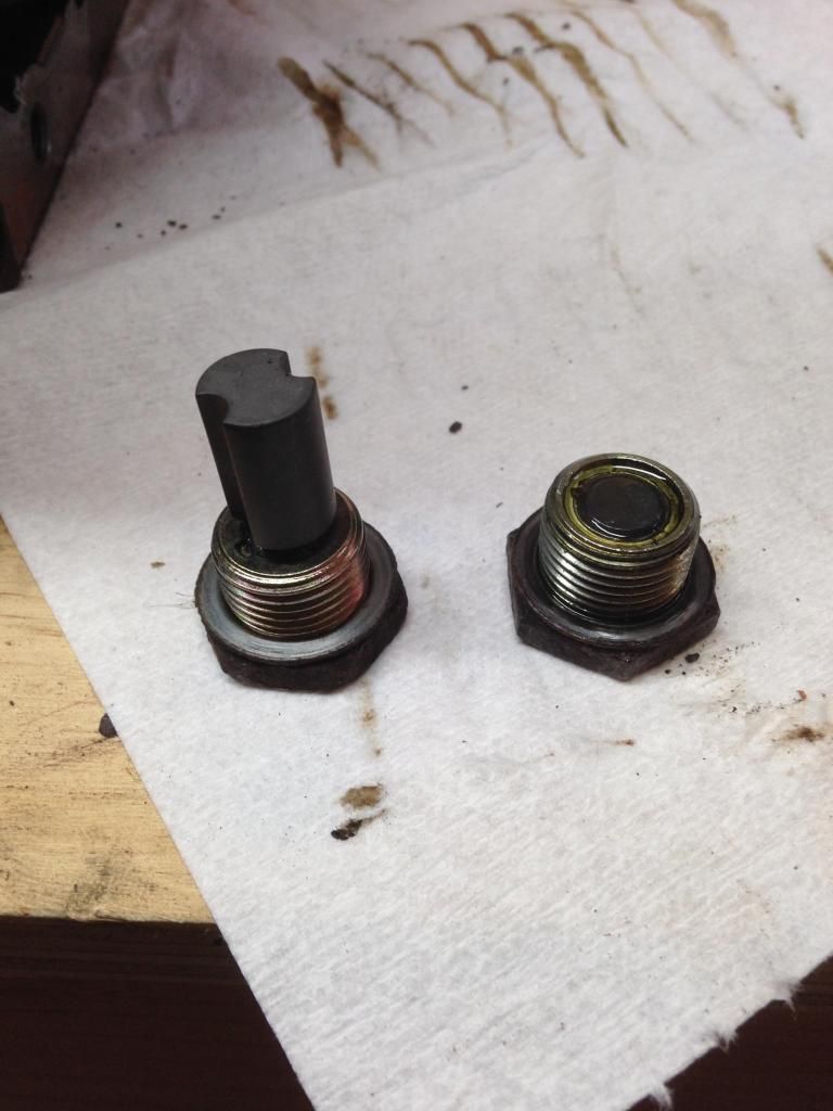
Overall I had a small shift in the pattern but its not enough to worry me and I have installed and ran this diff for about a month now at 520Whp with no noise or issues. Other things i noticed was a difference between a pre89 and post89 magnetic drain plugs. The 89+ is on the left. Its the same size thread for the drain plug and the fill plug so I put the pre89 magnetic plug in the fill hole so I have two magnetic plugs for extra protection.
I also originally filled this differential up with Carquest brand 75-90 gear oil. On the bottle is said "LSD top off only", so I figured there was no additive. When I first drove it around I noticed ZERO popping/creaking normally associated with a fresh rear and no LSD additive. After some reading on the forums and saw REDLINE 75-90NS (No LS additive) was recommended by a few people. I ordered some to give it a try. After putting the REDLINE in within minutes the rear was popping/creaking pretty fierce. I was a little nervous because it sounded like the rear sub frame was falling out, but i was very happy at the same time to know that the limited slip is much more limited now. I have added some REDLINE Additive since. They recommend a 4% solution. I added a little at a time and have reduced the popping/creaking a lot. It is still a little creaky but its MUCH better then it was before. I don't want to add anymore because i want the strong effect of the limited slip as my car makes decent power and the more traction i can get the better. I believe i ended up adding about 25 Milliliters with a small plastic syringe. I feel that I am at a good balance between traction and clutch life.
I'm sure there is a couple things I missed, or could have done better or different. This was how I did it and it worked for me. I also re-read this so many times to try to catch all of my horrible spelling and terrible grammar my head is spinning. Hope this helps someone. Feel free to ask questions/comments.
-Dan
