
Do a web search on DIY PCB's Eric it's not really hard to make them and there are a few options.
Stretch's Digidash thread
- Thread starter Stretch
- Start date
You are using an out of date browser. It may not display this or other websites correctly.
You should upgrade or use an alternative browser.
You should upgrade or use an alternative browser.
Thanks for the reply so quickly. I only fear that if I do that the board will be sone sort of rectangle, and that's just as shitty for this situation. It really has to be shaped for it to work. I'll google it right now anyway tho.
eric
eric
You could do it with wire wraps if it's not complex.
(Multi pinned board and you just run a bunch of wires instead of the printed circuits)
(Multi pinned board and you just run a bunch of wires instead of the printed circuits)
the other thing you can do is just cut the PCB and join the tracks with wire links and fold it behind if theres no components right on the cut line
Thanks for the replies. You guys got me thinking maybe i had a chance ahaha. I can't do that wire trick as there isn't room to cut any excess material off anyway, the harness plugs are the entire width of the widest part of the board! The ONLY way is to have a board custom made, since i looked and even flipping it won't work because the legs coming from the lcd screen aren't symetrical. The bottom ones are grouped large, and the top are little bunches so it wouldn't line up with the holes when flipped.. This sucks majorly.
eric
eric
Allan_MA70 said:the other thing you can do is just cut the PCB and join the tracks with wire links and fold it behind if theres no components right on the cut line
:withstupi I was going to say the same thing.
Stretch said:Thanks for the replies. You guys got me thinking maybe i had a chance ahaha. I can't do that wire trick as there isn't room to cut any excess material off anyway, the harness plugs are the entire width of the widest part of the board! The ONLY way is to have a board custom made, since i looked and even flipping it won't work because the legs coming from the lcd screen aren't symetrical. The bottom ones are grouped large, and the top are little bunches so it wouldn't line up with the holes when flipped.. This sucks majorly.
eric
Do you have any good pics of the rear of the boards?
Jimi: ROFLMAO Does Stretch have any good pics fullstop!! :wave:
(ya know I'm only teasing don't ya Eric)
(ya know I'm only teasing don't ya Eric)
Ahahah I got a bit better with my last 3 pic eh? I flashed with them, but it's still kinda shitty. I'll talk to my pops today, and see if I can get good pics of the board with either his camera, or possibly a friends'. I have to sleep now it's 3:18am here.
Later guys.
eric
Later guys.
eric
IJ. said:Jimi: ROFLMAO Does Stretch have any good pics fullstop!! :wave:
(ya know I'm only teasing don't ya Eric)
Haha.
Hey Stretch, anything can be made to work. But, if you give up, you can always give it all to me:biglaugh:
Jimi: Ya just have to look at the pics at the start of this he's got the "Turd Filter" working 100%! ")
Ya, I take blurry pics so you have to guess what it's about. Like spy photos of a concept car.
eric
eric
Stretch said:Thanks for the replies. You guys got me thinking maybe i had a chance ahaha. I can't do that wire trick as there isn't room to cut any excess material off anyway, the harness plugs are the entire width of the widest part of the board! The ONLY way is to have a board custom made, since i looked and even flipping it won't work because the legs coming from the lcd screen aren't symetrical. The bottom ones are grouped large, and the top are little bunches so it wouldn't line up with the holes when flipped.. This sucks majorly.
eric
desolder the display and put wires on it so you can move the board to the side
Here's just a small update to keep any watchers from becoming bored with my conversion :biglaugh:
I have done some fiberglassing on the left side of the cluster. I had to make this custom "pocket" to allow the depth of the board and all circuitry to fit correctly. It's the housing for the water temp screen, but I might just use it as my oil temp.
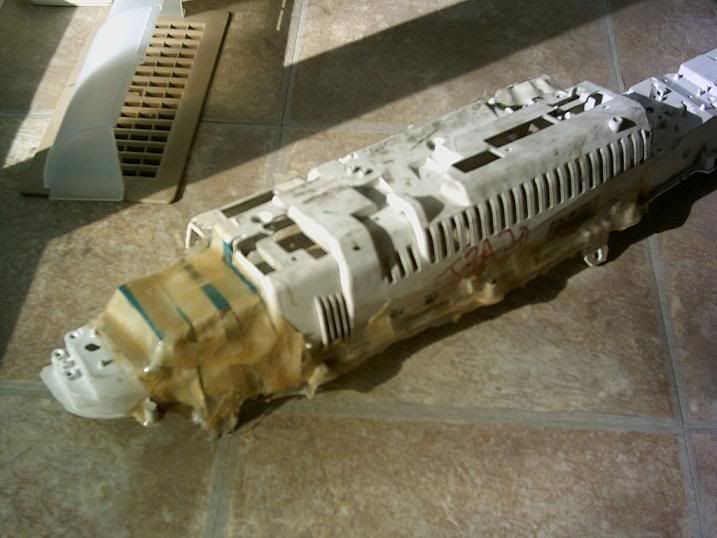
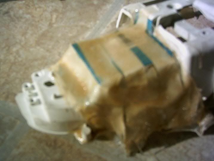
You can see in this close up the tape and blue cardboard I used as the skeleton for the fiberglass to droop over. Me not thinking enough before hand and not putting plastic wrap down over the cardboard made for a shitty turnout ahahaa.
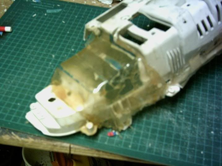
I took as much of it out as possible and put another coat of resin over it, so now it's MUCH cleaner, and the bond is better. I like how you can see through the fiberglass, I wish the whole cluster was like that.
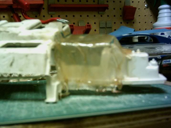
Another angle of my addition to the cluster, showing the shape better. I have a few more coats to do before I allow this to hold the electronics. I'll paint it after all so it goes better than this clear business. Either white to match the rest of the cluster, or I might do the whole cluster black to hide it incase you can see a bit of it from the driver's seat.
I'm going to my dad's house Sunday to talk about the board i had problems with. He'll most likely do the wiring work for me, since we both trust him more than me ahahaa.
eric
I have done some fiberglassing on the left side of the cluster. I had to make this custom "pocket" to allow the depth of the board and all circuitry to fit correctly. It's the housing for the water temp screen, but I might just use it as my oil temp.
You can see in this close up the tape and blue cardboard I used as the skeleton for the fiberglass to droop over. Me not thinking enough before hand and not putting plastic wrap down over the cardboard made for a shitty turnout ahahaa.
I took as much of it out as possible and put another coat of resin over it, so now it's MUCH cleaner, and the bond is better. I like how you can see through the fiberglass, I wish the whole cluster was like that.
Another angle of my addition to the cluster, showing the shape better. I have a few more coats to do before I allow this to hold the electronics. I'll paint it after all so it goes better than this clear business. Either white to match the rest of the cluster, or I might do the whole cluster black to hide it incase you can see a bit of it from the driver's seat.
I'm going to my dad's house Sunday to talk about the board i had problems with. He'll most likely do the wiring work for me, since we both trust him more than me ahahaa.
eric
neat i want to see it done just add wire to the pin outs liek what was said above and move it where ever the fuck you want
My dad's handling the board for me right now. I'll talk to him on Sunday to see if he got anywhere. I haven't done any work on the cluster since last update either. i did get a head I bought today, so I took it apart and sent it off to the machinist's to get cut/cleaned and maybe by the end of the week i can seal up my shortblock finally. I'll do more fiberglass work on Wed and post pics because I work on Tuesday and won't have time to do anything then.
eric
eric
MINI UPDATE:
Ok, I have been doing more glass work, and the pocket is almost ready for a test fit with the smallest circuit board, but that's small news right now so it won't be covered deeply.
the real news is I was over at my dad's house and he's been hard at work on the long board which was causing troubles fitting properly. I'll let the pics, aswell as some descriptions do the rest of the talking for now.
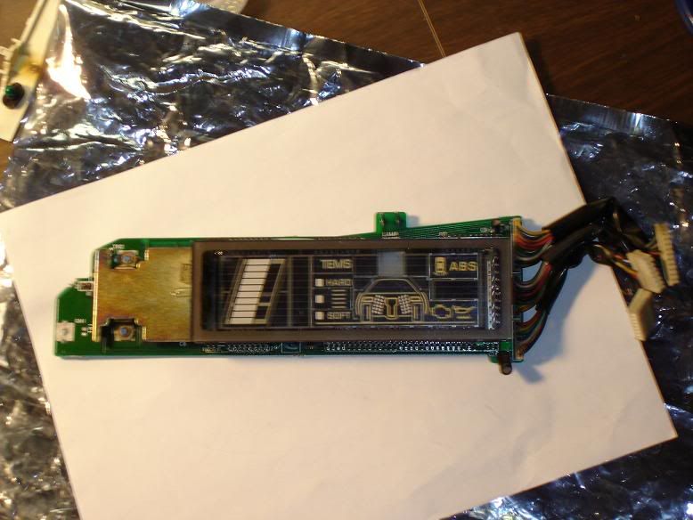
Here's a good (5.0 megapixel good, just for you IJ :biglaugh: ) pic of the board in question
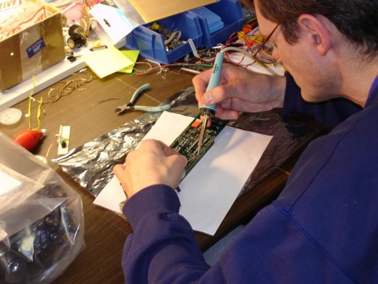
Here's a pic of my dad working on desoldering the display unit from the board. There are probably around 50-60 legs that have to be meticulously desoldered.
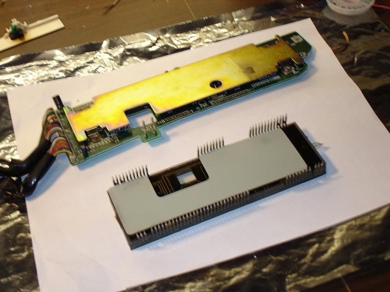
Here's an upside down view of how it looks when you first pull the display off the board. That grey piece is a rubber insolator of some kind. You can also see that metal piece which protects all the delicate chips etc...
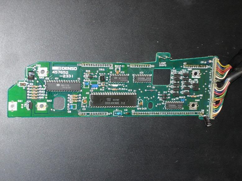
This is the board, less all of the other pieces. You can see all of the circuitry! I'm not sure if any of you have seen this part of the cluster before.
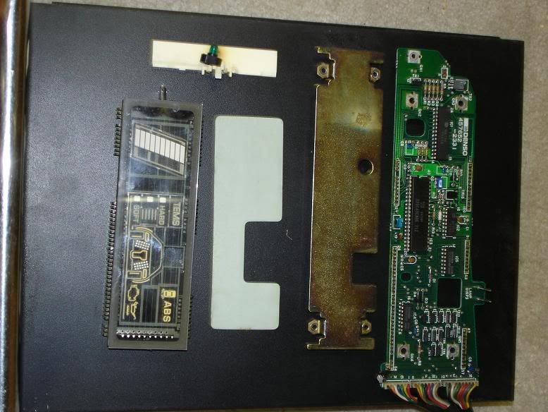
Here's all of the pieces lined up from left to right. The pieces layer from the board to the display.
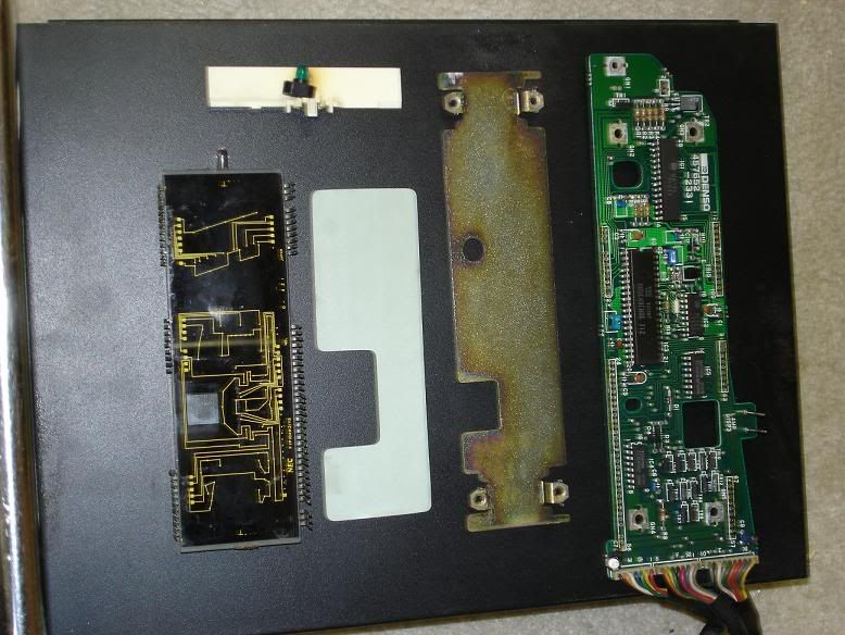
Same pic as above, except the main display is flipped over and reveals the wicked underside. It looks very interresting to say the least!
My next update will most likely be either when this board is further along, or when I test fit the mini board into the glass pocket I made.
eric
Ok, I have been doing more glass work, and the pocket is almost ready for a test fit with the smallest circuit board, but that's small news right now so it won't be covered deeply.
the real news is I was over at my dad's house and he's been hard at work on the long board which was causing troubles fitting properly. I'll let the pics, aswell as some descriptions do the rest of the talking for now.
Here's a good (5.0 megapixel good, just for you IJ :biglaugh: ) pic of the board in question
Here's a pic of my dad working on desoldering the display unit from the board. There are probably around 50-60 legs that have to be meticulously desoldered.
Here's an upside down view of how it looks when you first pull the display off the board. That grey piece is a rubber insolator of some kind. You can also see that metal piece which protects all the delicate chips etc...
This is the board, less all of the other pieces. You can see all of the circuitry! I'm not sure if any of you have seen this part of the cluster before.
Here's all of the pieces lined up from left to right. The pieces layer from the board to the display.
Same pic as above, except the main display is flipped over and reveals the wicked underside. It looks very interresting to say the least!
My next update will most likely be either when this board is further along, or when I test fit the mini board into the glass pocket I made.
eric