Wiring Injectors to eManage on 1JZ

hockysa

New Member
Hey guys, as some of you might know the 1JZ only has 3 injector feed lines.
I'm currently trying to wire up the injector harness on the 1JZ but am unsure of how to do it.

I'm aware I need to double up the wires on the EMB

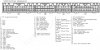
On the ECU pin out the injector feed lines go
Line1 Cylinders 1,4
Line2 Cylinders 3,5
and Line3 Cylinders 2,6

So when I double up do I wire it up

I/J CH-1 and 4 to #1
I/J CH-3 and 5 to #2
I/J CH-2 and 6 to #3

or

I/J CH-1 and 2 to #1
I/J CH-3 and 4 to #2
I/J CH-5 and 6 to #3

Cheers,
Benjamin
 

hockysa

New Member
Well this is interesting.
After some advice, I've now wired it up the ECU

EMB I/J CH-1 and 4 to #1 INJ ECU
EMB I/J CH-3 and 5 to #2 INJ ECU
EMB I/J CH-2 and 6 to #3 INJ ECU

and it won't start now.
It turns then dies almost straight away

Also I don't get why my interaction light is always lit orange without the USB cable connected
 

suprastanger507mgte

2x88+2x89+1x91+2x92=ME
Apr 5, 2005
3,148
6
38
Hayward , Ca
per diagram T-10 from the emanage manual,
Hook it up as in the emanage manual 'Example 2, inline 6 engines, the wires for channel 'A' and 'B' you can leave off, that's for driving additional injectors.
The ground wire is teed into the ecu ground wire, that's pin #E in the diagram T-10.

So for the emanage injector harness, you would connect from the Emanage side, Injector Channel 1 (Blue/Red) and Injector Channel 4 (Purple/Red) to the ECU side #1.

Injector Channel 2 (Orange/Red) and Injector Channel 6 (Light Blue/Red) to #2.

Channel 3 (Yellow/Red) and Channel 5 Pink/Red) to #3
 

hockysa

New Member
suprastanger507mgte;1520621 said:
per diagram T-10 from the emanage manual,
Hook it up as in the emanage manual 'Example 2, inline 6 engines, the wires for channel 'A' and 'B' you can leave off, that's for driving additional injectors.
The ground wire is teed into the ecu ground wire, that's pin #E in the diagram T-10.

So for the emanage injector harness, you would connect from the Emanage side, Injector Channel 1 (Blue/Red) and Injector Channel 4 (Purple/Red) to the ECU side #1.

Injector Channel 2 (Orange/Red) and Injector Channel 6 (Light Blue/Red) to #2.

Channel 3 (Yellow/Red) and Channel 5 Pink/Red) to #3

How did you come up with which channel to pair up?

Because I got those pairs from the ECU Pinout
attachment.php
 

Attachments

  • attachment.jpg
    attachment.jpg
    74.6 KB · Views: 126

johnd-mkiv

New Member
Jul 12, 2010
14
0
0
Essex
Can someone please confirm the correct way to wire these in, as there seams to be so many orders in the above :)

john