
Calling electronic gurus on the board that can help me design a circuit or modify an existing controller for PWM solenoid control.
Long and Short:
Manually control a 12v Solenoid in the transmission used to regulate pressure.
PWM from 0-100%
Problem:
Vehicle is too sluggish to fully apply/never fully applies
I have measured all aspects of the circuit that I would like to mimic.
2 wire solenoid, + comes from TCU, - grounded internally inside transmission
Driven by 12V PWM signal at a constant 50Hz
Solenoid 12.6 ohms
Typical operation:
V, A & PWM on time %
P - 0V 0A 0%
R - 3.6V 0.25A 42%
N - 0V 0A 0%
D - 3.6V 0.25A 42%
3 - 3.6V 0.25A 42%
2 - 3.6V 0.25A 42%
1 - 5.3V 0.38A 55%
Full lock up would draw 0.95A @ 100%
I do not have an oscilloscope so I would expect the voltages to actually be 12V, since my multimeter is just averaging the pulses.
The plan is to wire a switch to toggle between normal operation and manual control. Manual control will only be used under certain circumstances for short periods to achieve full or close to full lock up. A dummy load would be used during manual switch over to convince the TCU it is still in control of the Solenoid.
Another problem is that it would have to use a high side driver since there is no access to the ground wire on the solenoid.
On another board I found someone that was tackling the same issue but never finished.
Here is a circuit that was proposed.
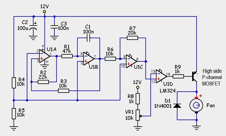
As he explained it the fan should be the solenoid and transistor should be MOSFET (IRF630B). I believe he was designing it for a 17 ohm solenoid, so that could be an issue as mine is 12.6.
I am not an electrical engineer so I am a little lost in the construction of this circuit.
Anyone know of any off the shelf units that could work or be modified to work?
http://store.qkits.com/moreinfo.cfm/MX033
I saw this one but the Hz is off and requires both the solenoid + and -, which I don't have access too.
Any help would be appreciated.
:1zhelp:
Long and Short:
Manually control a 12v Solenoid in the transmission used to regulate pressure.
PWM from 0-100%
Problem:
Vehicle is too sluggish to fully apply/never fully applies
I have measured all aspects of the circuit that I would like to mimic.
2 wire solenoid, + comes from TCU, - grounded internally inside transmission
Driven by 12V PWM signal at a constant 50Hz
Solenoid 12.6 ohms
Typical operation:
V, A & PWM on time %
P - 0V 0A 0%
R - 3.6V 0.25A 42%
N - 0V 0A 0%
D - 3.6V 0.25A 42%
3 - 3.6V 0.25A 42%
2 - 3.6V 0.25A 42%
1 - 5.3V 0.38A 55%
Full lock up would draw 0.95A @ 100%
I do not have an oscilloscope so I would expect the voltages to actually be 12V, since my multimeter is just averaging the pulses.
The plan is to wire a switch to toggle between normal operation and manual control. Manual control will only be used under certain circumstances for short periods to achieve full or close to full lock up. A dummy load would be used during manual switch over to convince the TCU it is still in control of the Solenoid.
Another problem is that it would have to use a high side driver since there is no access to the ground wire on the solenoid.
On another board I found someone that was tackling the same issue but never finished.
Here is a circuit that was proposed.
As he explained it the fan should be the solenoid and transistor should be MOSFET (IRF630B). I believe he was designing it for a 17 ohm solenoid, so that could be an issue as mine is 12.6.
I am not an electrical engineer so I am a little lost in the construction of this circuit.
Anyone know of any off the shelf units that could work or be modified to work?
http://store.qkits.com/moreinfo.cfm/MX033
I saw this one but the Hz is off and requires both the solenoid + and -, which I don't have access too.
Any help would be appreciated.
:1zhelp:

