
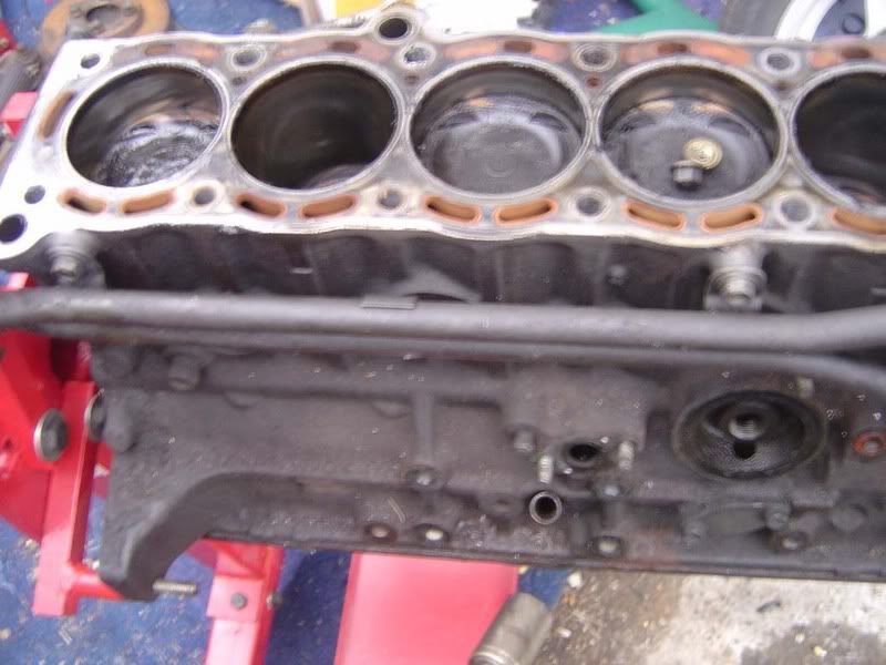
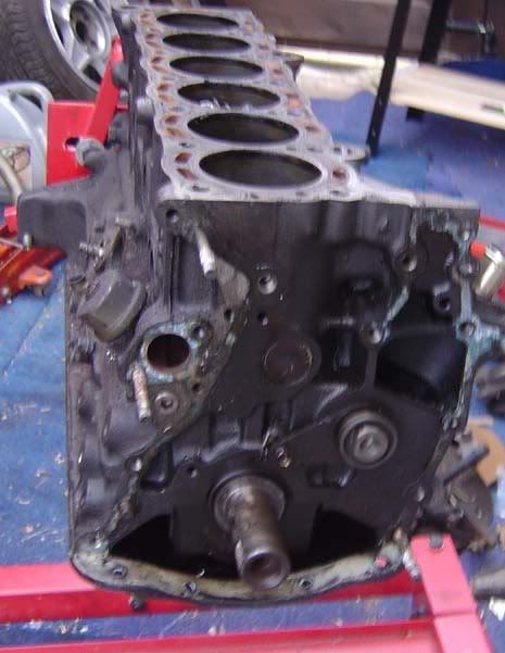
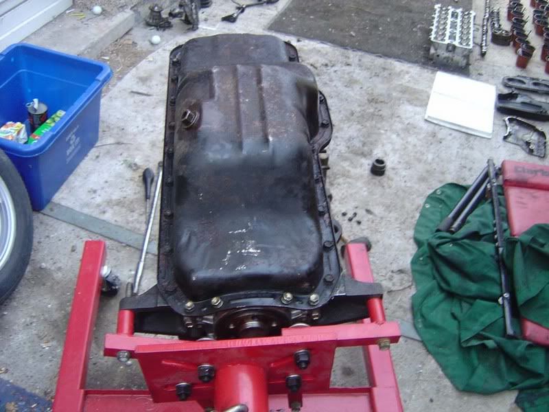
Once you've followed the guide for engine removal and cylinder head stripdown you can move on to stripping the block. A couple of bits are missing (engine mounts and a stay or two) but it's pretty much what you'll be faced with and all the important bits are here.
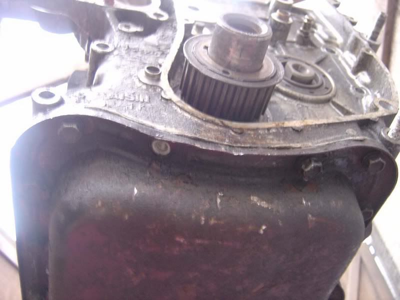
Step 1 - Start with the water pump, you've got a load of nuts and bolts holding this on, mainly 12mm but some 14mm
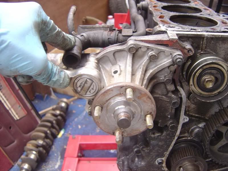
Step 2 - A tap with a rubber mallet may be needed to break the seal once you've removed all the bolts
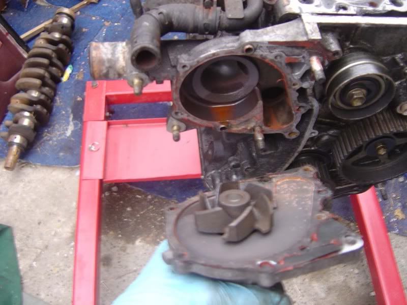
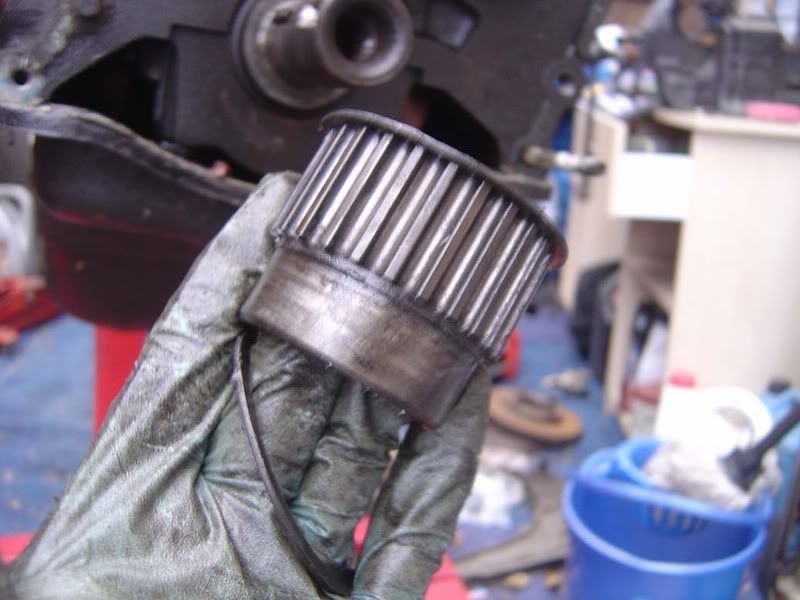
Step 3 - Pull the pump clear of the engine and check the blades for signs of corrosion. This one wasn't too bad
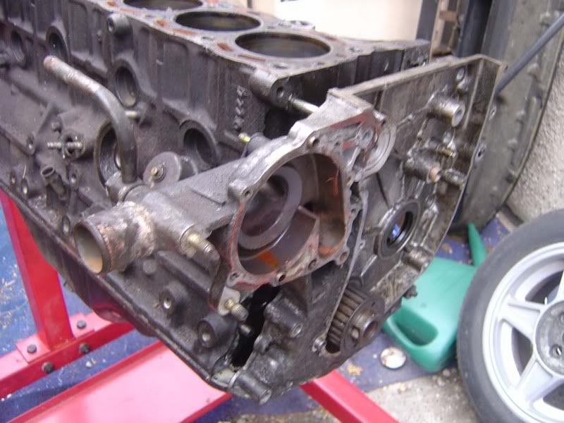
Step 4 - Remove the 14mm bolt holding the cam belt tensioner in place
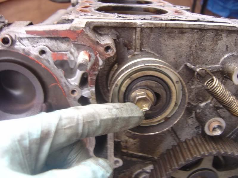
Step 5 - You'll need to unhook the spring and then pull the tensioner clear
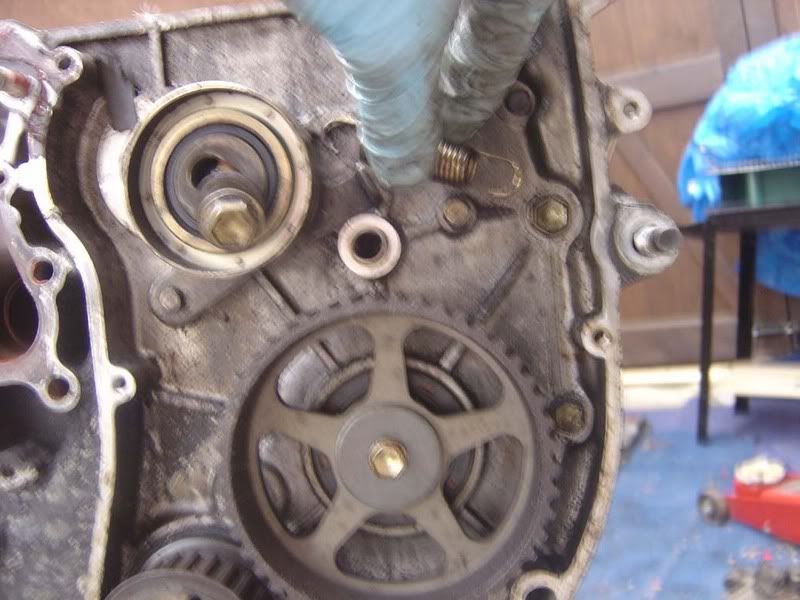
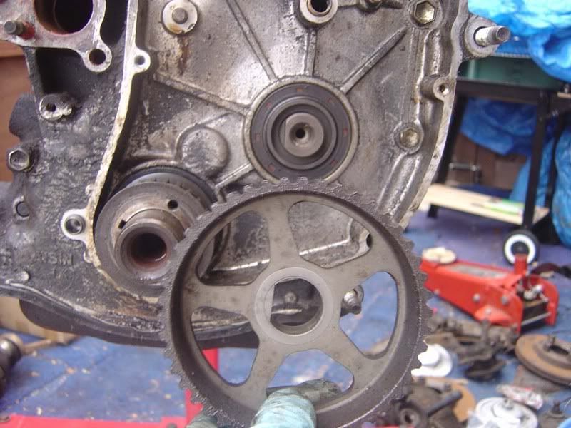
Step 6 - Lock the oil pump pulley (the big one) by sliding a screwdriver through the spokes and holding it against one of the casting masks in the block. I did it using the timing belt but that's only because I couldn't be bothered to grab a screwdriver!
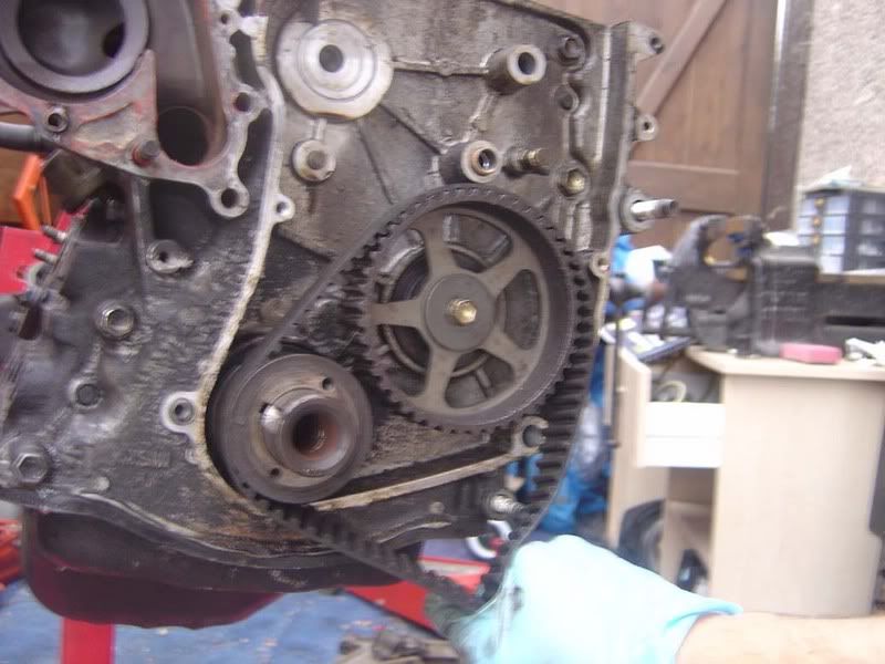
Step 7 - Remove the 14mm bolt completely and the pulley will fall away
Step 8 - Now work round removing all the 12mm bolts for the rear timing belt case
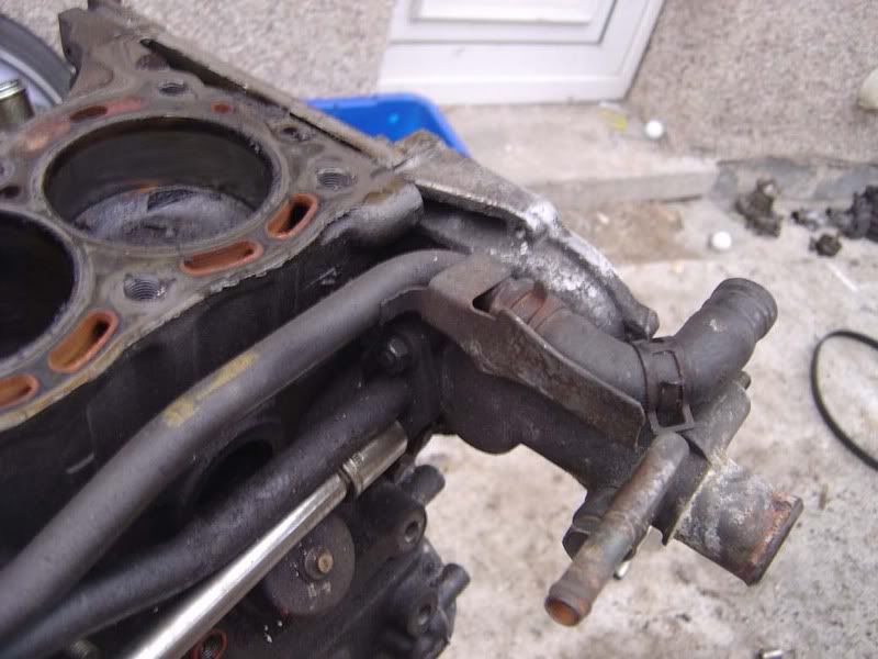
Step 9 - You'll need to remove the coolant return lines before you can remove the rear cover so get the two 12mm bolts in picture 1. Then the 12mm holding the lines to the block (picture 2). Then the final bolt holding the coolant hardpipes is on the inlet side of the engine (picture 3).
Step 10 - The front 4 bolts of the sump will need to be removed before you can take the rear timing belt case off, these are 12mm again
Step 11 - You may need to tap in a screwdriver to separate the sealant on the sump from the rear timing cover then it will pull away.
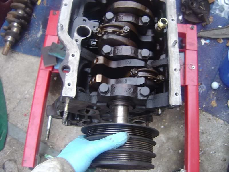
Step 12 - Note you need to remove the real crank pulley (the bit we've referred to previously is actually the harmonic damper) before the rear timing case will come off. I use the cover to help ease it off. You can get a puller to remove the pulley but if you get a long screwdriver behind the timing cover you can lever it off
Step 13 - There is another woodruff key arrangement for the crank pulley so remove this from the crankshaft and keep it safe
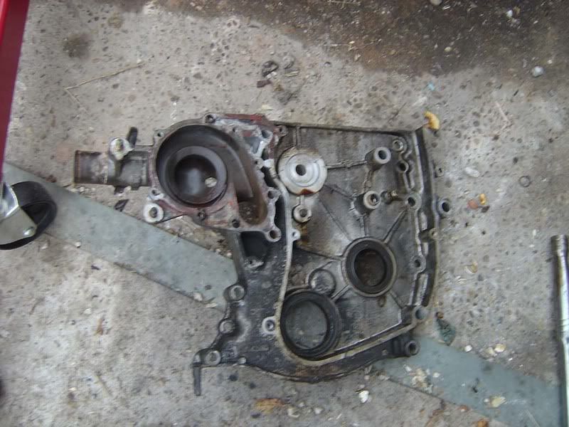
Step 14 - The rear cover can be put to one side now
Step 15 - The head is gradually shrinking to something less scary now!
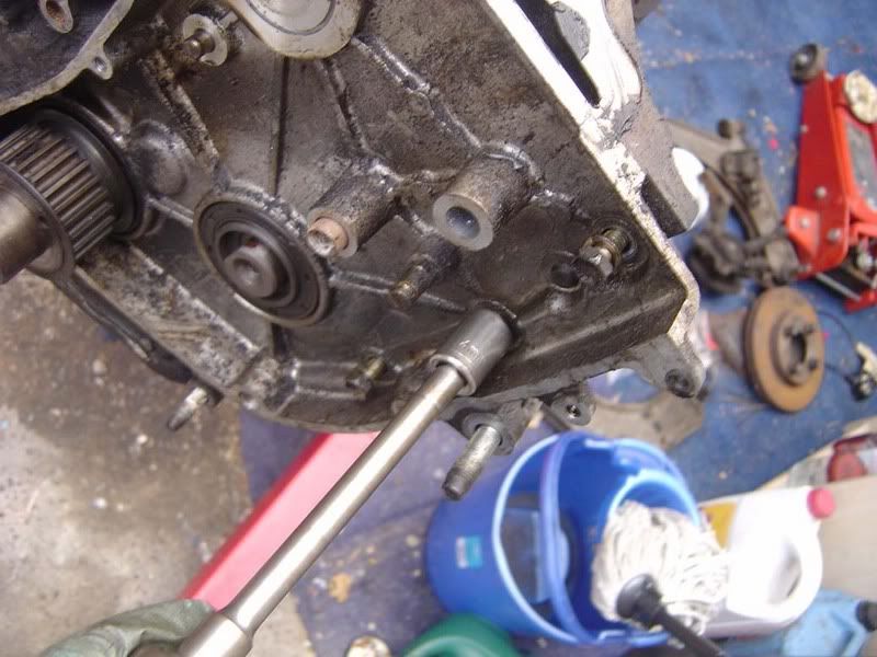
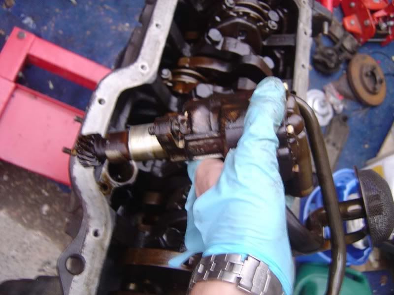
Step 16 - onto the oil pump drive shaft, remove the 14mm bolt shown in the picture
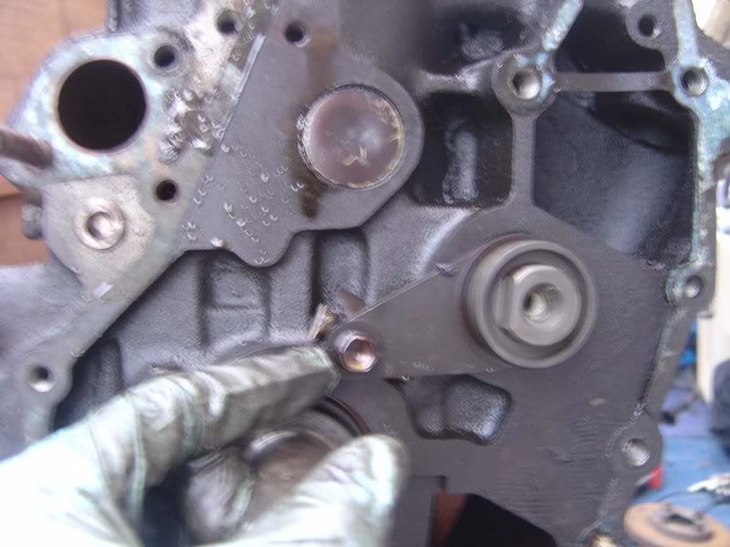
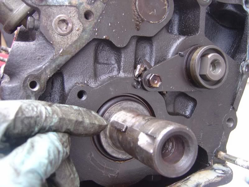
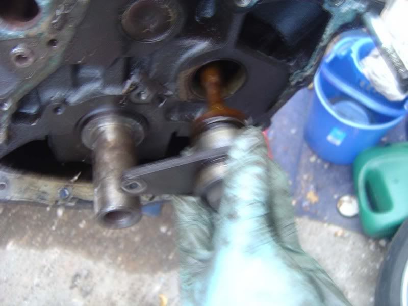
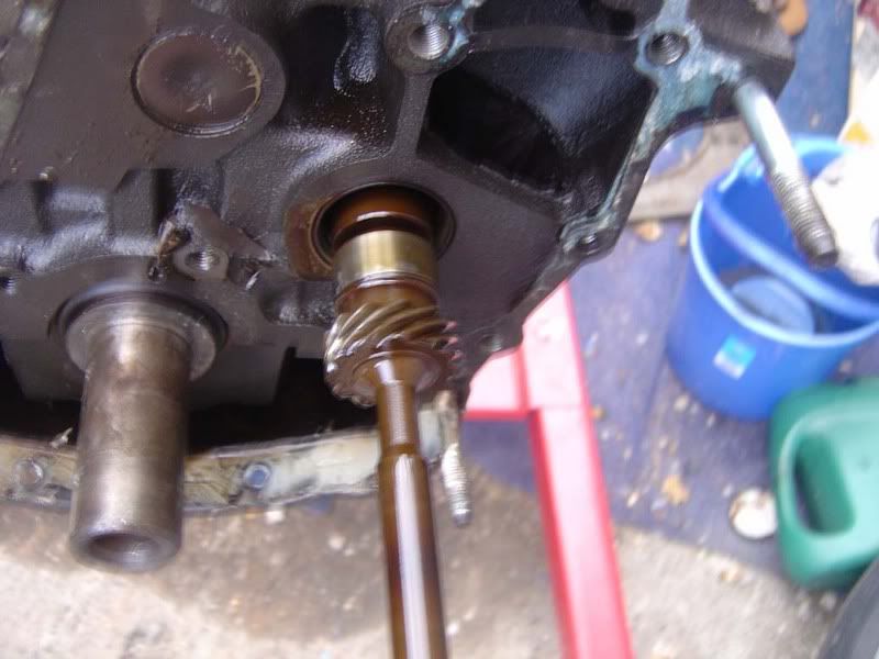
Step 17 - Now pull the drive shaft out, it might need a bit of wiggling but try not to catch it on the block on the way out. You'll need to disengage the skew gear (picture 2) as it slides out
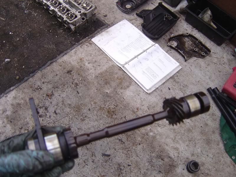
Step 18 - Here's a picture of the oil pump driveshaft, the left hand shiny silver bit is the number 1 bearing and the metal bit after the skew gear on the right is the number 2 bearing.
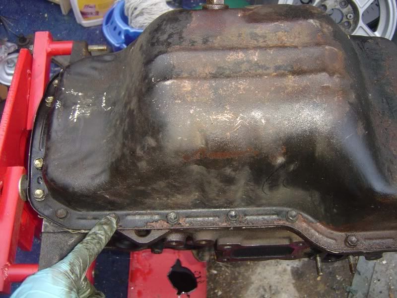
Step 19 - Spin the engine upside down (your engine stand should do this) so you can gain access to the sump
Step 20 - Remove all the 12mm bolts around the outside of the sump. Two of them are nuts and the rest are bolts
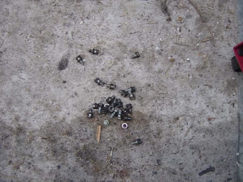
Step 21 - Once you've got all the bolts out (picture 1, there are lots!), tap a screwdriver/gasket scraper around the face of the sump where it meets the block (picture 2) to break the seal - the 'instant gasket' sealant is Toyota's recommended sealant so don't be surprised when you find that.
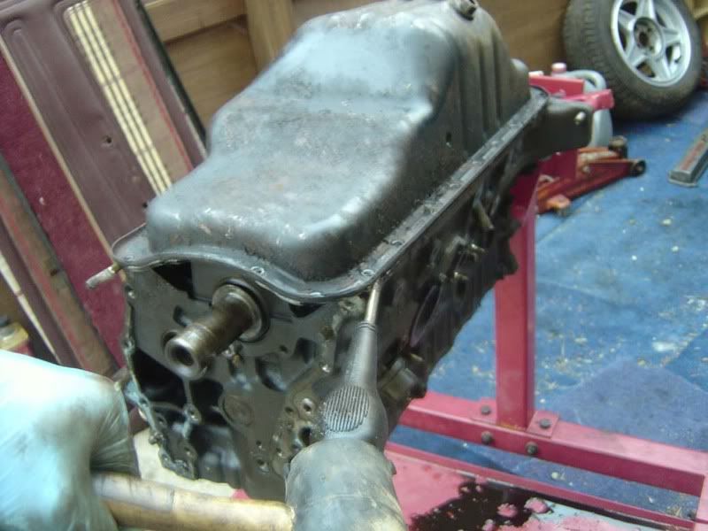
Step 22 - Once you've broken the sump's seal it will lift away to reveal the bottom end
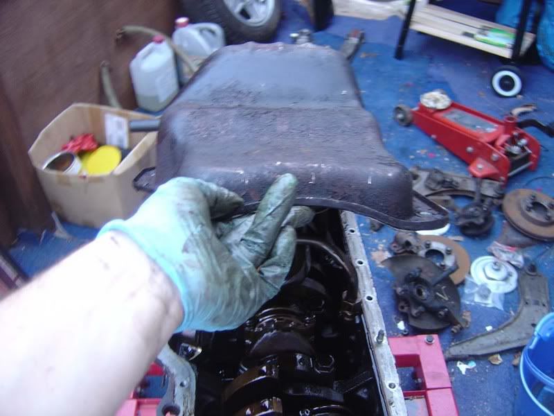
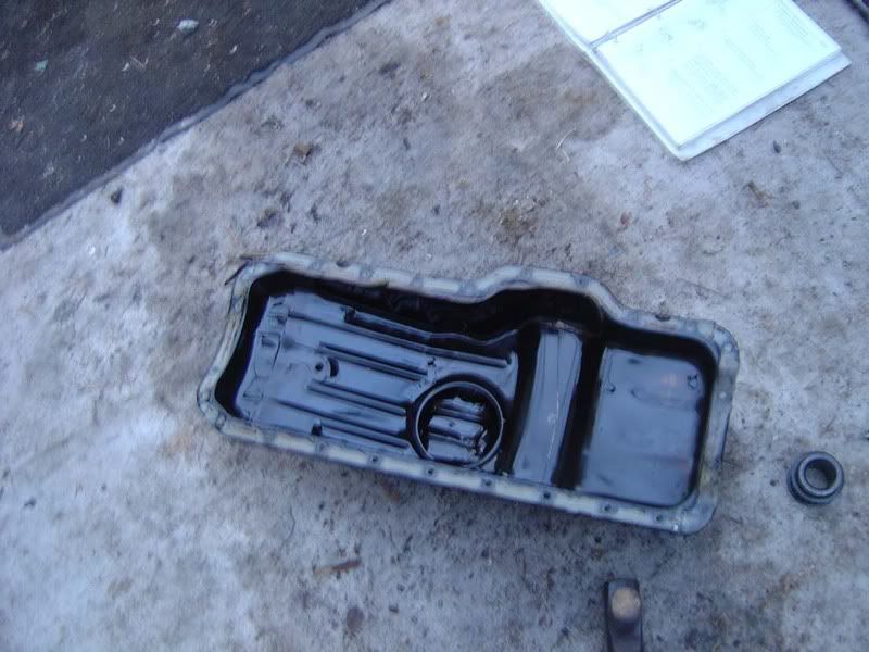
Step 23 - Now you know what the inside of a sump looks like (picture 1) and the bottom end of an engine (picture 2 which is blurry and rubbish!)
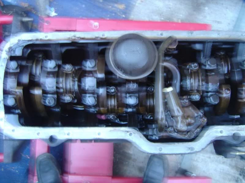
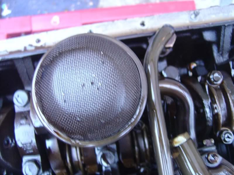
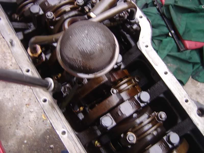
Step 24 - the strainer thing you can see is the mesh filter for the oil pump, if you find a lot of metal here then you may have other problems to start looking for
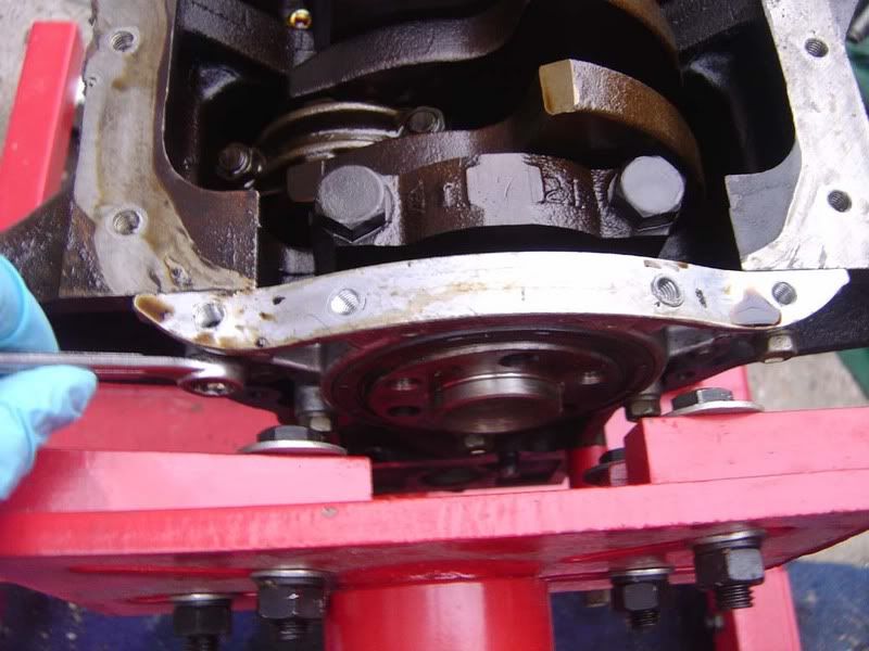
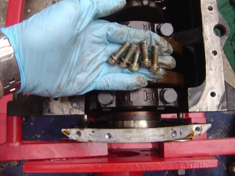
Step 25 - Take a 12mm ring spanner to the bolts holding the rear crank oil seal retainer in place. If your engine stand is like mine then this is a bit difficult to do! I removed all the bolts then eased the cover off its dowels (as shown in the second picture) so I can later remove the crank
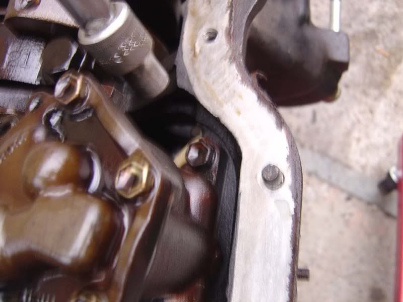
Step 26 - Remove the 10mm bolt for the oil pump (picture 1), then the 12mm on the other side (picture 2)
Step 27 - Really poor picture, sorry but take a 23mm spanner to the main oil line bolt and slacken it off completely (don't try and bend the pipe away though!)
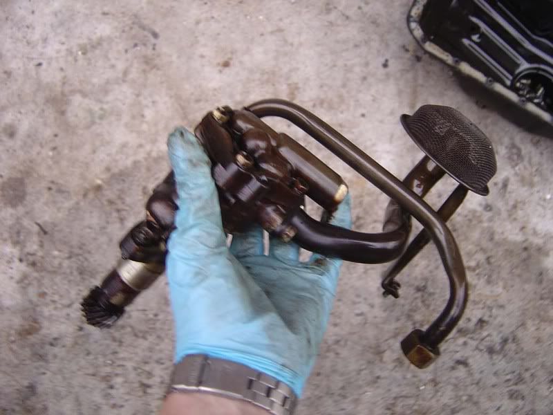
Step 28 - Lift the oil pump clear of the engine (it may need a little tug)
Step 29 - A nice shot of the pump itself, you can see the mesh use for straining the oil picked up from the sump, the skew drive gear which meshed with the oil pump driveshaft (step 15) and the outlet from the pump. The part I am holding is the main body of the pump which is spun by the skew gear causing the oil to suck through the strainer and out the main oil line
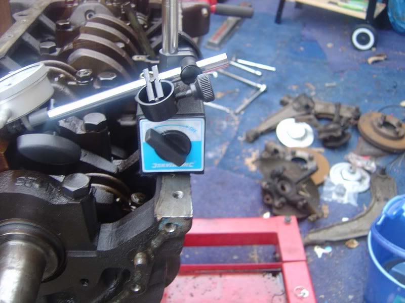
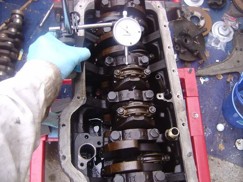
Step 30 - You need to invest in a dial indicator gauge, this is used to measure very small thrust clearances. It will cost you about £15-£20 typically and isn't the kind of tool you have lying around! You really have to have a stand with it for it to be of any use, once you've seen how sensitive they are you'll know why. I picked a cracking unit up off ebay with stand for £25 (delivered) and it had an electromagnetic stand so you could mount it on the block, turn the magnet on and forget about it - highly recommend "powertoolsukdirect" on ebay
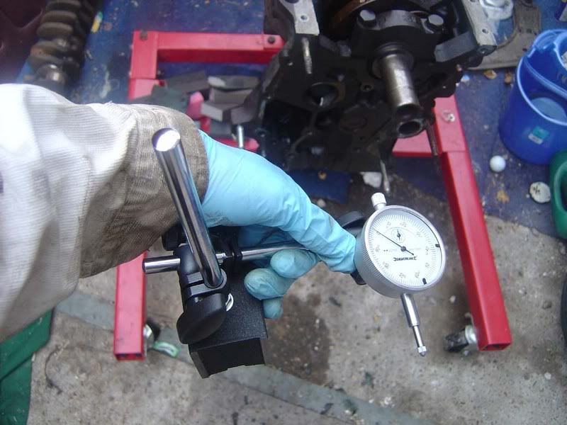
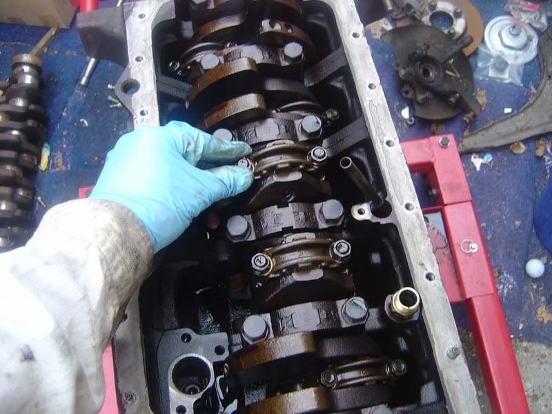
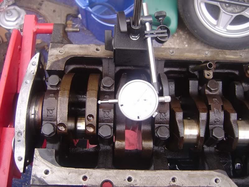
Step 31- Mount the gauge on the block somewhere, I used the face of the block that meets the sump. We are going to measure the big end bearing's movement at the base of the con rod.
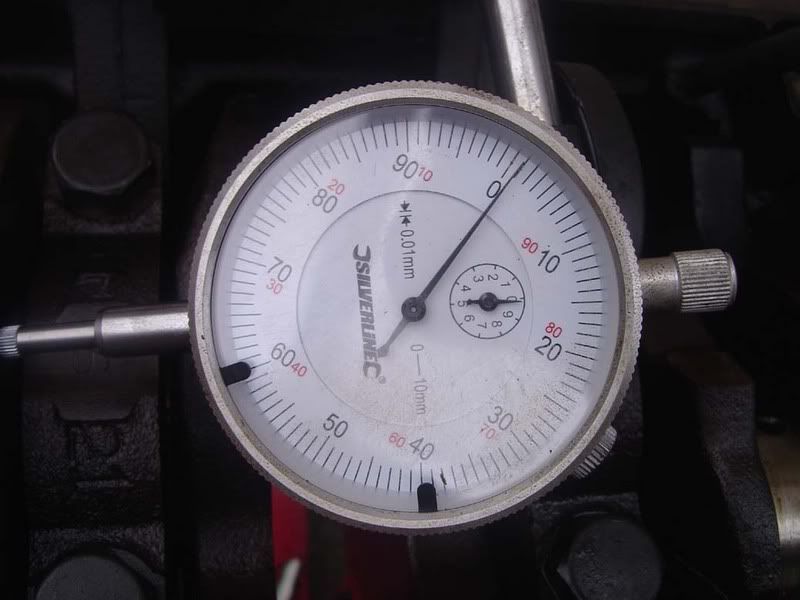
Step 32 - Carefully zero the gauge, you hopefully have a fine adjustment dial on your stand to move the gauge until it touches the part you are measuring - I set mine so it was 0.001 mm on the gauge so you knew you had no play in between the gauge and the rod.
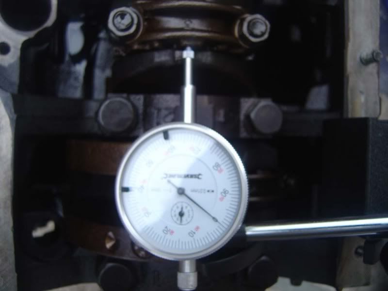
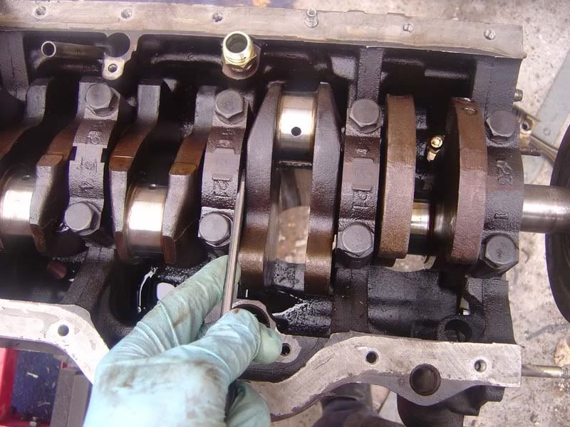
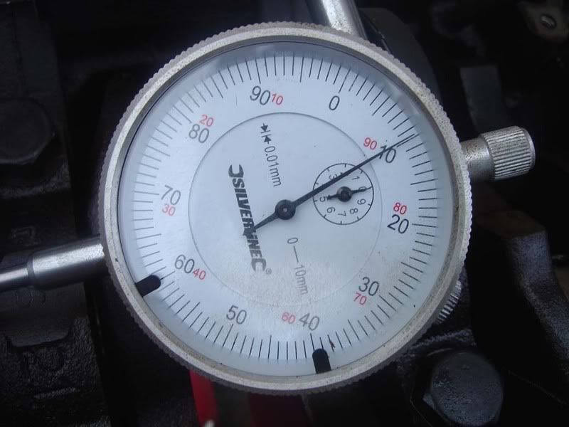
Step 33 - This shows you the part being measured. We are measuring the thrust clearance for each con rod so you push the bearing fully forward, align the dial indicator gauge then pull the bearing backwards and see how much movement you measure. Use the TSRM but anything under 0,3mm is good, mine were all fine
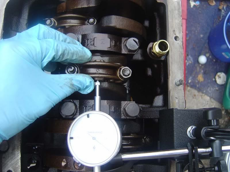
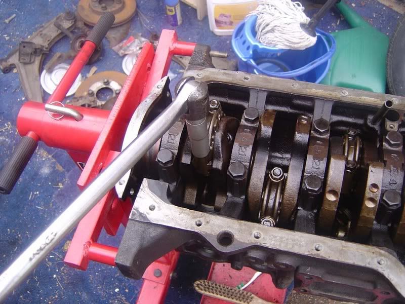
Step 34 - Note you will need to rotate the crank to get access to each of the big ends to measure thrust clearance. To do this, pop the harmonic damper onto the end of the crank (no need to a woodruff key), it will be a pretty tight fit and there's no real resistance in the engine now so you can turn it over very easily
Step 35 - You'll be able to do the cylinders in pairs, 1 and 6, 2 and 3 then 3 and 4 will be in the right positions as you rotate the crank.
Step 36 - Note for 3 and 4 it will be easier to measure the clearance from the back of the engine facing forwards as shown due to the dowels for the sump sticking out
I've attached a video here which shows:
- Mounting position for the gauge
- The dial being zeroed with the adjuster knob on the stand
- The movement in the big end we are capturing
- The amount of freeplay detected
- How the gauge works and how sensitive it is
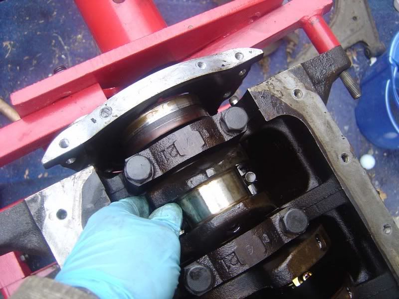
Step 37 - Once you've measure all the clearances you can start removing the rods and pistons. There are two 14mm bolts holding each one on and they will be pretty tight so use a breaker bar to crack these off (picture 1) then a turn or so with a ratchet (picture 2) is all you need before the bolts can be taken off with your fingers (picture 3. Order is not important, there are only two bolts but do each a little at a time, don't undo one then the other!
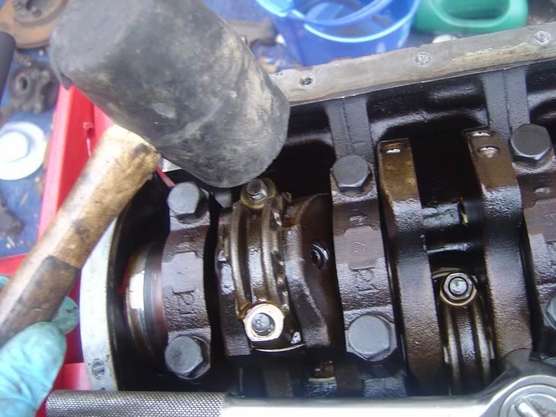
Step 38 - Now a gentle tap with a rubber mallet on the studs will drops the rod/piston a little
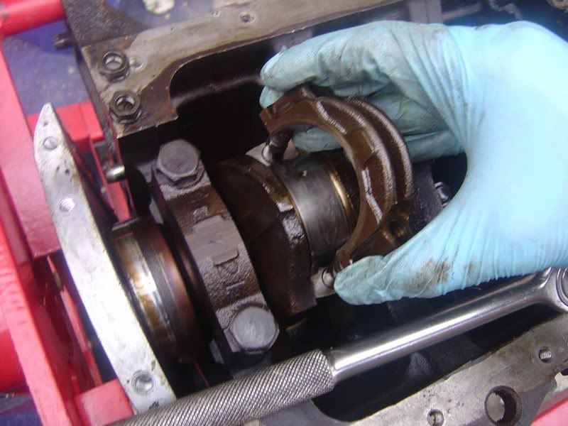
Step 39 - You should now be able to pull the big end cap and bearing out
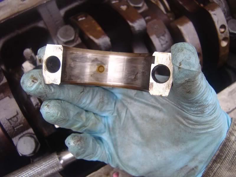
Step 40 - Take a look at the inside of the bearing and you'll see a stain where the oil hole sits. We'll talk through inspection of bearings (and everything else!) in another guide
Step 41 - A magnetic parts tool will make bearing removal easy when they stick to the crank (which they almost always do)
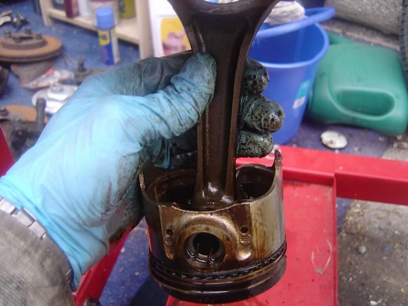
Step 42 - Working on your own you need to use a bit of ingenuity, here's my method - wrap a towel around underneath the cylinder you are working on (picture 1).
Hold the towel in place with your fingers while you push the rod bolts down with your thumbs (picture 2)
Once the piston rings leave the bore the rod and piston will glide down into the towel. Grab both ends of the towel in one hand and reach down with the other to slide out the rod/piston assembly
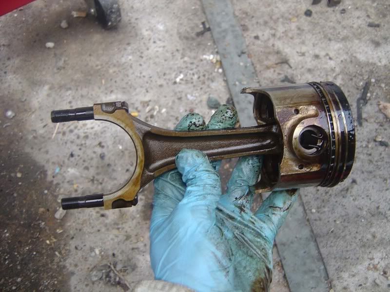
Step 43 - The TSRM suggests a piece of tube over the rod bolts to prevent damage to the crank/cylinders when removing the rod but if you're careful there's no need. A firm push is required to get the rings out the bore but easily achievable by hand pushing the rod bolts (see picture)
Step 44 - Remove each rod and piston in this manner and keep them all in order
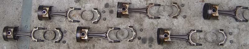
Step 45 - As always, keep everything nice and neat. Order is very important. You will end up with something like this
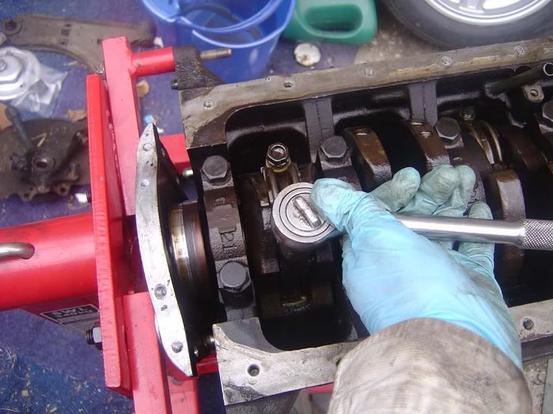
Step 46 - Crankshaft thrust clearance next, just like before with the dial indicator gauge (picture 1). Start by forcing the crank in one direction, set up the gauge then force the crank in the other direction. A screwdriver should be used between a main bearing cap and the crank to move it as shown in picture 2. Again, I set the gauge to just show a reading (picture 3) before measuring the clearance. With a max of 0.30mm allowed you should hope for something similar to the results I got (picture 4)
Step 47 - Now you've measure the crank play / 'end float' / thrust, you can start removing the main bearings and caps that hold the crank in the cylinder block. These are 19mm bolts and again will be stiff so use the breaker bar. It's very important you follow the torque pattern on these to avoid bending/snapping the crankshaft. You really don't want to stress this
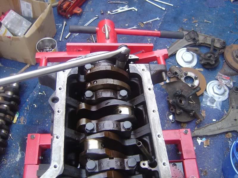
Step 48 - After a pass with the breaker bar cracking off the nuts, a couple of passes doing 1/2 turn or so with the ratchet (picture 1) is advised before undoing the bolts completely (picture 2)
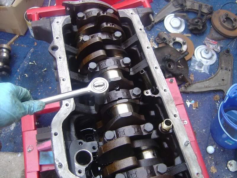
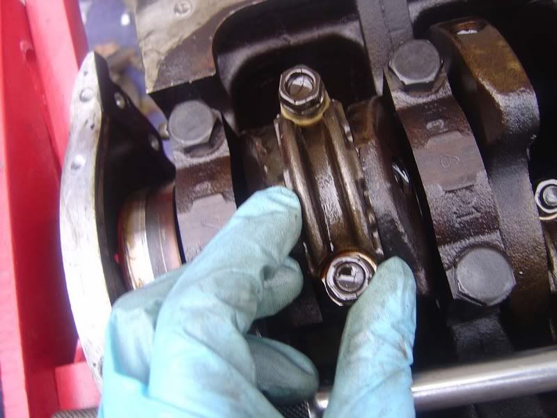
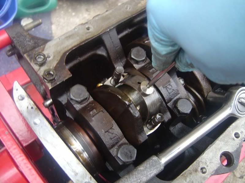
Step 49 - To remove the main bearing caps, pull the nuts up so they are protruding from the cap slightly (picture 1). Now push the cap in one direction with a steady force (I needed one hand to take the picture in pic 2 but you'd obviously use one hand on each of the bolts).
Once you've cracked the cap off, squeeze the two bolts together and wiggle it back and forth whilst pulling upwards (picture 3) and it will come away from the crank (picture 4)
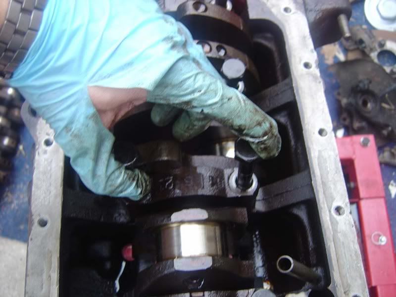
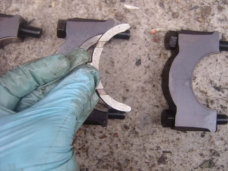
Note that the middle cap has thrust bearings to reduce crank thrust movement so you will need to pull this one up without wiggling so it can be more difficult (picture 5 shows the cap being removed with washers and picture 6 shows the thrust bearings)
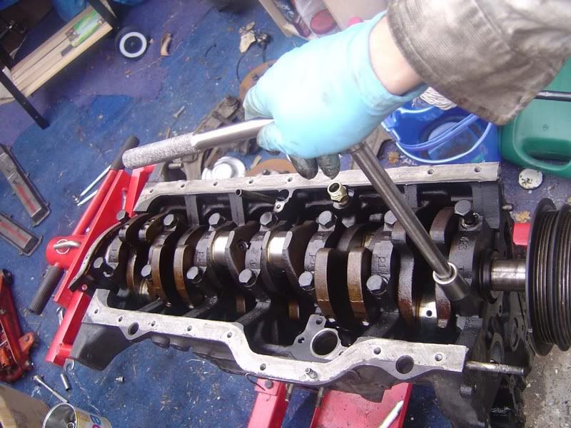
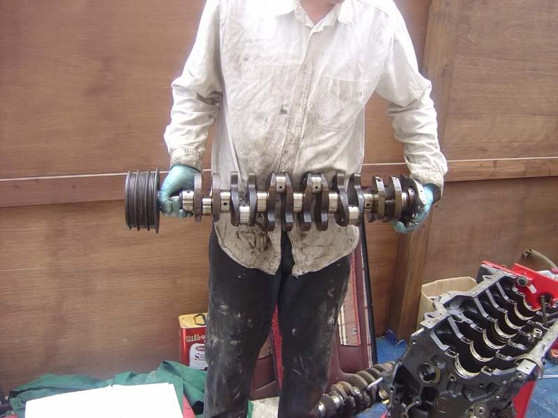
Step 50 - The crank can come out now but it's pretty heavy so make sure you can lift 60 ish kgs on your own or get a helper (I got one to take photos!)
Make sure the rear crank seal is clear of the dowels when you remove the crank.
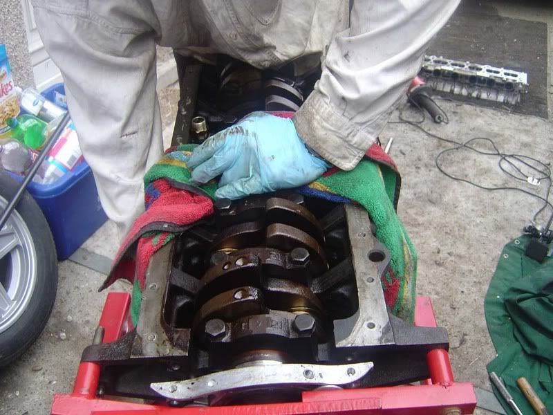
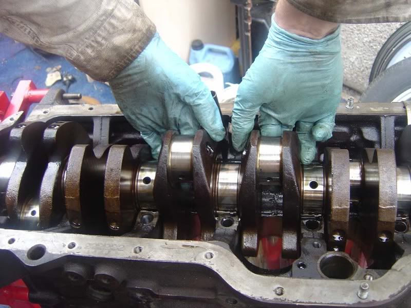
Rotate the crank so cylinders 3 and 4 are at BDC (the crank pins are sticking out the bottom of the block) as shown in picture 1
I advise you try to lift each end of the crank up slightly at this stage to break any oil seal formed
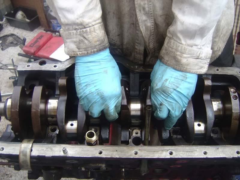
Get a firm grip on the two pins (picture 2) and rock the crank forwards then backwards (just once) as you ease it out
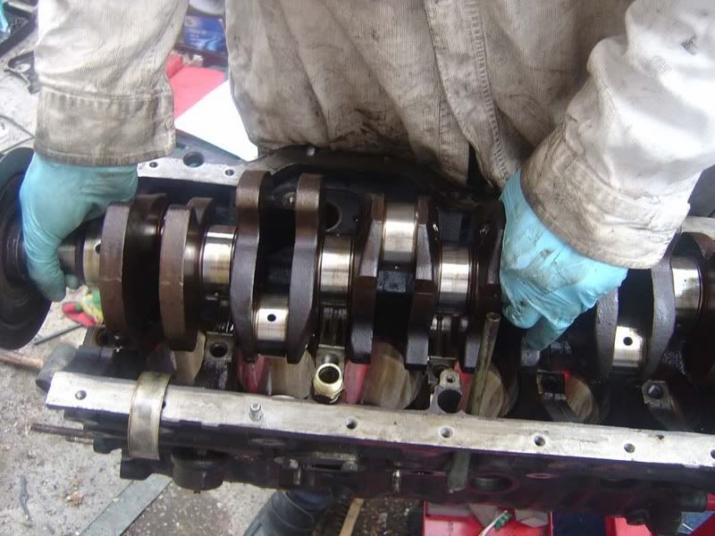
Lift the crank cleanly up then grab the nose (front) of the crank so you can carry it easily as shown in picture 3
Picture 4 shows the crank in all its glory
By the way, as you lift it and hear a clattering of metal don't panic! It's just the thrust washers on the underside dropping away and nothing to worry about.
Step 1 - Start with the water pump, you've got a load of nuts and bolts holding this on, mainly 12mm but some 14mm
Step 2 - A tap with a rubber mallet may be needed to break the seal once you've removed all the bolts
Step 3 - Pull the pump clear of the engine and check the blades for signs of corrosion. This one wasn't too bad
Step 4 - Remove the 14mm bolt holding the cam belt tensioner in place
Step 5 - You'll need to unhook the spring and then pull the tensioner clear
Step 6 - Lock the oil pump pulley (the big one) by sliding a screwdriver through the spokes and holding it against one of the casting masks in the block. I did it using the timing belt but that's only because I couldn't be bothered to grab a screwdriver!
Step 7 - Remove the 14mm bolt completely and the pulley will fall away
Step 8 - Now work round removing all the 12mm bolts for the rear timing belt case
Step 9 - You'll need to remove the coolant return lines before you can remove the rear cover so get the two 12mm bolts in picture 1. Then the 12mm holding the lines to the block (picture 2). Then the final bolt holding the coolant hardpipes is on the inlet side of the engine (picture 3).
Step 10 - The front 4 bolts of the sump will need to be removed before you can take the rear timing belt case off, these are 12mm again
Step 11 - You may need to tap in a screwdriver to separate the sealant on the sump from the rear timing cover then it will pull away.
Step 12 - Note you need to remove the real crank pulley (the bit we've referred to previously is actually the harmonic damper) before the rear timing case will come off. I use the cover to help ease it off. You can get a puller to remove the pulley but if you get a long screwdriver behind the timing cover you can lever it off
Step 13 - There is another woodruff key arrangement for the crank pulley so remove this from the crankshaft and keep it safe
Step 14 - The rear cover can be put to one side now
Step 15 - The head is gradually shrinking to something less scary now!
Step 16 - onto the oil pump drive shaft, remove the 14mm bolt shown in the picture
Step 17 - Now pull the drive shaft out, it might need a bit of wiggling but try not to catch it on the block on the way out. You'll need to disengage the skew gear (picture 2) as it slides out
Step 18 - Here's a picture of the oil pump driveshaft, the left hand shiny silver bit is the number 1 bearing and the metal bit after the skew gear on the right is the number 2 bearing.
Step 19 - Spin the engine upside down (your engine stand should do this) so you can gain access to the sump
Step 20 - Remove all the 12mm bolts around the outside of the sump. Two of them are nuts and the rest are bolts
Step 21 - Once you've got all the bolts out (picture 1, there are lots!), tap a screwdriver/gasket scraper around the face of the sump where it meets the block (picture 2) to break the seal - the 'instant gasket' sealant is Toyota's recommended sealant so don't be surprised when you find that.
Step 22 - Once you've broken the sump's seal it will lift away to reveal the bottom end
Step 23 - Now you know what the inside of a sump looks like (picture 1) and the bottom end of an engine (picture 2 which is blurry and rubbish!)
Step 24 - the strainer thing you can see is the mesh filter for the oil pump, if you find a lot of metal here then you may have other problems to start looking for
Step 25 - Take a 12mm ring spanner to the bolts holding the rear crank oil seal retainer in place. If your engine stand is like mine then this is a bit difficult to do! I removed all the bolts then eased the cover off its dowels (as shown in the second picture) so I can later remove the crank
Step 26 - Remove the 10mm bolt for the oil pump (picture 1), then the 12mm on the other side (picture 2)
Step 27 - Really poor picture, sorry but take a 23mm spanner to the main oil line bolt and slacken it off completely (don't try and bend the pipe away though!)
Step 28 - Lift the oil pump clear of the engine (it may need a little tug)
Step 29 - A nice shot of the pump itself, you can see the mesh use for straining the oil picked up from the sump, the skew drive gear which meshed with the oil pump driveshaft (step 15) and the outlet from the pump. The part I am holding is the main body of the pump which is spun by the skew gear causing the oil to suck through the strainer and out the main oil line
Step 30 - You need to invest in a dial indicator gauge, this is used to measure very small thrust clearances. It will cost you about £15-£20 typically and isn't the kind of tool you have lying around! You really have to have a stand with it for it to be of any use, once you've seen how sensitive they are you'll know why. I picked a cracking unit up off ebay with stand for £25 (delivered) and it had an electromagnetic stand so you could mount it on the block, turn the magnet on and forget about it - highly recommend "powertoolsukdirect" on ebay
Step 31- Mount the gauge on the block somewhere, I used the face of the block that meets the sump. We are going to measure the big end bearing's movement at the base of the con rod.
Step 32 - Carefully zero the gauge, you hopefully have a fine adjustment dial on your stand to move the gauge until it touches the part you are measuring - I set mine so it was 0.001 mm on the gauge so you knew you had no play in between the gauge and the rod.
Step 33 - This shows you the part being measured. We are measuring the thrust clearance for each con rod so you push the bearing fully forward, align the dial indicator gauge then pull the bearing backwards and see how much movement you measure. Use the TSRM but anything under 0,3mm is good, mine were all fine
Step 34 - Note you will need to rotate the crank to get access to each of the big ends to measure thrust clearance. To do this, pop the harmonic damper onto the end of the crank (no need to a woodruff key), it will be a pretty tight fit and there's no real resistance in the engine now so you can turn it over very easily
Step 35 - You'll be able to do the cylinders in pairs, 1 and 6, 2 and 3 then 3 and 4 will be in the right positions as you rotate the crank.
Step 36 - Note for 3 and 4 it will be easier to measure the clearance from the back of the engine facing forwards as shown due to the dowels for the sump sticking out
I've attached a video here which shows:
- Mounting position for the gauge
- The dial being zeroed with the adjuster knob on the stand
- The movement in the big end we are capturing
- The amount of freeplay detected
- How the gauge works and how sensitive it is
Step 37 - Once you've measure all the clearances you can start removing the rods and pistons. There are two 14mm bolts holding each one on and they will be pretty tight so use a breaker bar to crack these off (picture 1) then a turn or so with a ratchet (picture 2) is all you need before the bolts can be taken off with your fingers (picture 3. Order is not important, there are only two bolts but do each a little at a time, don't undo one then the other!
Step 38 - Now a gentle tap with a rubber mallet on the studs will drops the rod/piston a little
Step 39 - You should now be able to pull the big end cap and bearing out
Step 40 - Take a look at the inside of the bearing and you'll see a stain where the oil hole sits. We'll talk through inspection of bearings (and everything else!) in another guide
Step 41 - A magnetic parts tool will make bearing removal easy when they stick to the crank (which they almost always do)
Step 42 - Working on your own you need to use a bit of ingenuity, here's my method - wrap a towel around underneath the cylinder you are working on (picture 1).
Hold the towel in place with your fingers while you push the rod bolts down with your thumbs (picture 2)
Once the piston rings leave the bore the rod and piston will glide down into the towel. Grab both ends of the towel in one hand and reach down with the other to slide out the rod/piston assembly
Step 43 - The TSRM suggests a piece of tube over the rod bolts to prevent damage to the crank/cylinders when removing the rod but if you're careful there's no need. A firm push is required to get the rings out the bore but easily achievable by hand pushing the rod bolts (see picture)
Step 44 - Remove each rod and piston in this manner and keep them all in order
Step 45 - As always, keep everything nice and neat. Order is very important. You will end up with something like this
Step 46 - Crankshaft thrust clearance next, just like before with the dial indicator gauge (picture 1). Start by forcing the crank in one direction, set up the gauge then force the crank in the other direction. A screwdriver should be used between a main bearing cap and the crank to move it as shown in picture 2. Again, I set the gauge to just show a reading (picture 3) before measuring the clearance. With a max of 0.30mm allowed you should hope for something similar to the results I got (picture 4)
Step 47 - Now you've measure the crank play / 'end float' / thrust, you can start removing the main bearings and caps that hold the crank in the cylinder block. These are 19mm bolts and again will be stiff so use the breaker bar. It's very important you follow the torque pattern on these to avoid bending/snapping the crankshaft. You really don't want to stress this
Step 48 - After a pass with the breaker bar cracking off the nuts, a couple of passes doing 1/2 turn or so with the ratchet (picture 1) is advised before undoing the bolts completely (picture 2)
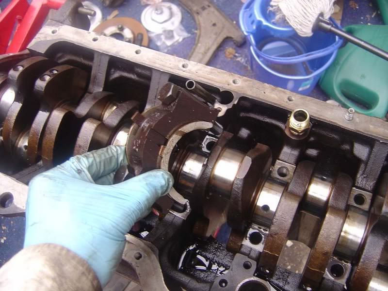
Step 49 - To remove the main bearing caps, pull the nuts up so they are protruding from the cap slightly (picture 1). Now push the cap in one direction with a steady force (I needed one hand to take the picture in pic 2 but you'd obviously use one hand on each of the bolts).
Once you've cracked the cap off, squeeze the two bolts together and wiggle it back and forth whilst pulling upwards (picture 3) and it will come away from the crank (picture 4)
Note that the middle cap has thrust bearings to reduce crank thrust movement so you will need to pull this one up without wiggling so it can be more difficult (picture 5 shows the cap being removed with washers and picture 6 shows the thrust bearings)
Step 50 - The crank can come out now but it's pretty heavy so make sure you can lift 60 ish kgs on your own or get a helper (I got one to take photos!)
Make sure the rear crank seal is clear of the dowels when you remove the crank.
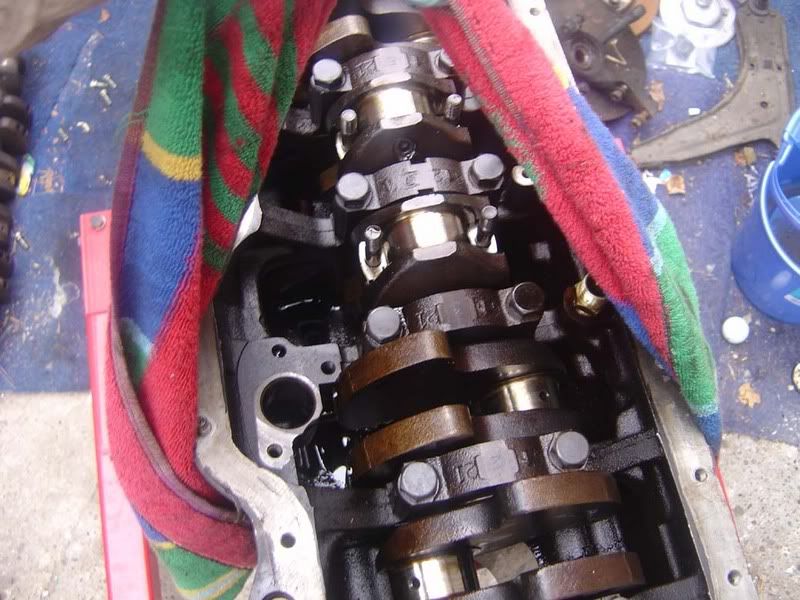
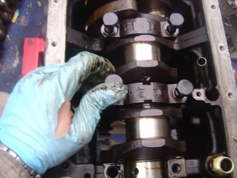
Rotate the crank so cylinders 3 and 4 are at BDC (the crank pins are sticking out the bottom of the block) as shown in picture 1
I advise you try to lift each end of the crank up slightly at this stage to break any oil seal formed
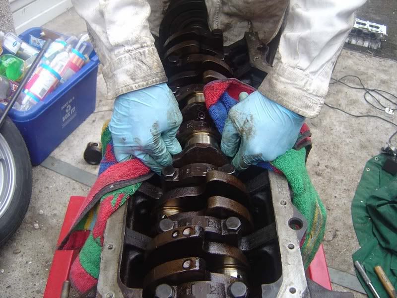
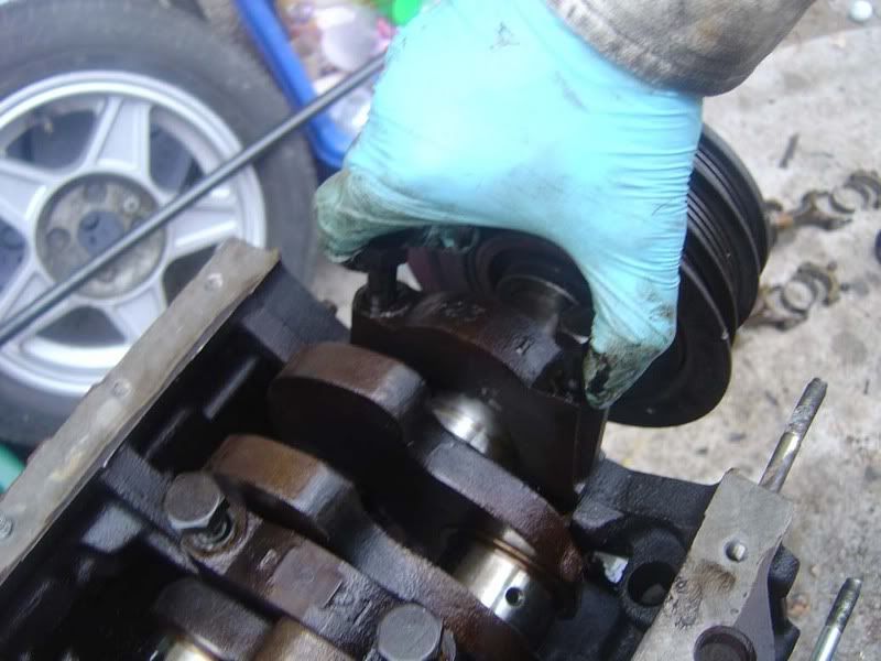
Get a firm grip on the two pins (picture 2) and rock the crank forwards then backwards (just once) as you ease it out
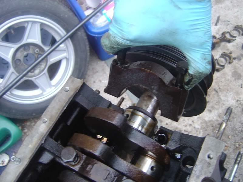
Lift the crank cleanly up then grab the nose (front) of the crank so you can carry it easily as shown in picture 3
Picture 4 shows the crank in all its glory
By the way, as you lift it and hear a clattering of metal don't panic! It's just the thrust washers on the underside dropping away and nothing to worry about.