In a 4 stroke engine the piston will :
a) Move down the chamber/cylinder/hole in the block during the intake stroke where it creates a vacuum and sucks in fresh charge (air)
b) When it reaches the bottom (known as ‘Bottom Dead Centre’ or BDC),the piston will momentarily stop and then change direction for the compression stroke where 130-140 psi of gas pressure will be generated and must be sealed.
c) Once the piston reaches the top of its travel it will stop again (this time we are at ‘Top Dead Centre’ or TDC). The piston then heads back down the chamber on the power stroke where the piston is subjected to the full force of the combustion
d) After the piston has been forced down the chamber it will hit BDC again and then head up on the exhaust stroke pushing all the hot exhaust gases up towards the cylinder head where it escapes
The extreme temperatures the pistons and block are exposed to will cause the metal to expand. The bores (and the whole ‘block’ of the engine) are made of cast iron whereas the pistons themselves are an aluminium alloy so there will be differences in expansion rates here. The difference in expansion rates of the piston and block need to be considered when specifying clearances for the engine.
Note that the cast iron block has cooling channels through it whereas the piston must rely on direct cooling through the oil system and passing heat through the bores to the block. Due to the need for expansion and also the fact the piston needs to move within the bore, a small clearance gap is found between the piston and the cylinder.
More commonly with forged pistons, the clearance can be quite large between the piston and bore when cold (this is to allow for piston expansion) and so the piston can make a noise as it comes into contact with the block when moving up and down the chamber. This is an audible phenomena referred to as ‘piston slap’ and usually disappears when warmed up but can damage cylinder walls. See below for more information on side thrust which causes this. This is reduced with modern techniques for skirt design (read on for piston skirts) and metal treatment/alloys allowing smaller clearances between the piston and cylinder. It is desirable to have a low coefficient for thermal expansion which means we want a material that doesn’t get a lot larger as it heats up.
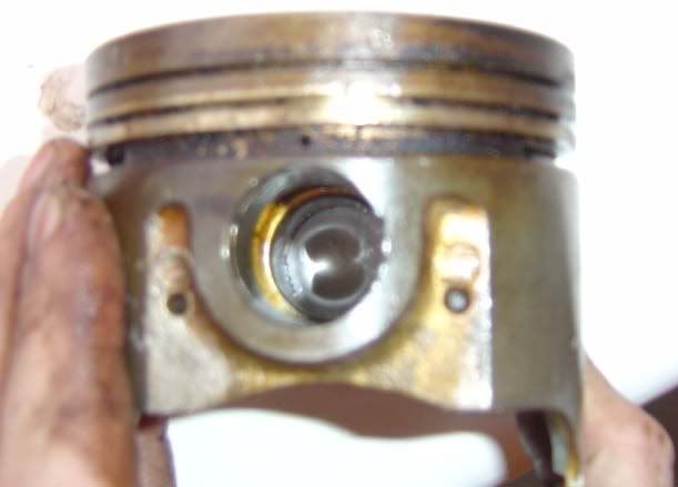
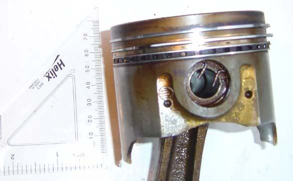
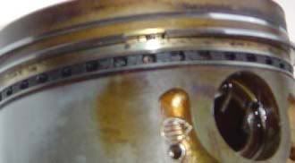
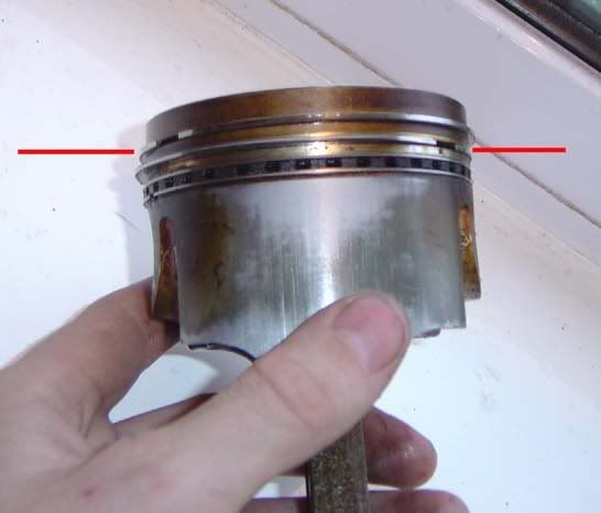
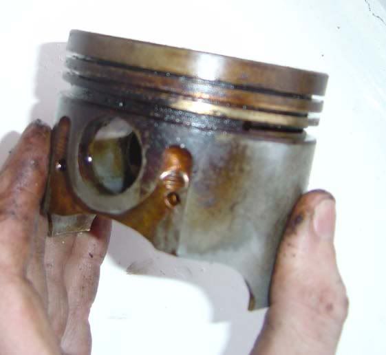
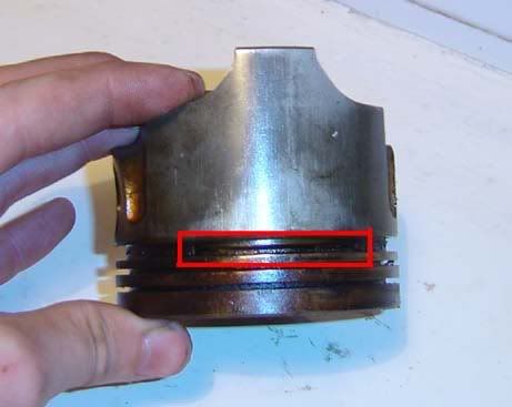
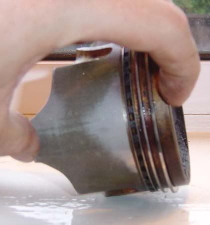
Obviously if we have a gap between the cylinder and the piston then any gas will try to escape past this. To prevent this, ‘piston rings’ are fitted to the piston. Typically (as with the Supra) there are three rings fitted, the first two being compression rings (also called gas rings or pressure rings) and the third is an oil scraper ring (see picture below). The three rings together are referred to as the ‘ring belt’

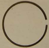
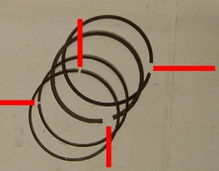
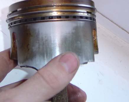
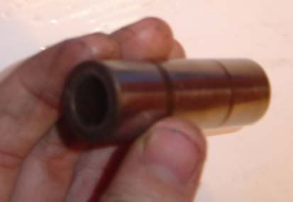
The compression rings prevent gases from bypassing the piston and heading towards the sump (known as ‘blow-by’ gases). The rings themselves are not a complete circle and have a small gap to allow them to be expanded for fitting/removal from the piston. This gap is set to a specific value known as the ‘end gap’ or ‘working gap’ and varies for different piston manufacturers and applications. The gap should be large enough to ensure that there is still a clearance between the ends of the ring after exposure to normal cylinder temperatures but not so large that significant blow-by will occur. Below shows the end gap
To set the gap you usually put the ring into a cylinder and level it off with the piston before using a feeler gauge to check the clearance and a file to alter the size.
Note that the end gap is larger when the piston is not in the cylinder due to the fact the ring springs out to a greater diameter when not surrounded by the cylinder. When the ring is not fitted, the gap is known as the ‘free gap’ (see picture). The material used in the piston rings is selected to ensure they spring outwards towards the cylinder when installed.
The end gaps will let a small amount of gas bypass the ring and head past this initial seal. A second compression ring is fitted and the end gap for this piston ring is usually set ‘out of phase’ from the other. By this I mean it is not lined up but set 90 degrees apart (360 degrees in a circle and we have 4 rings to fit-because the oil scraper ring comprises of two smaller rings-so 360/4=90 degrees). See below for the alignment:
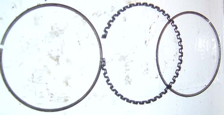
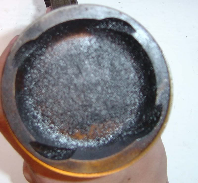
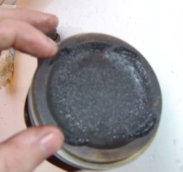
The primary ring is made of stainless steel and the second is cast iron on the Supra. See picture for the end gaps :
With the two compression rings working together (sometimes even 3 are used but not on Supras) a tight enough seal is formed to prevent much gas escaping from the combustion chamber into the crankcase. The third ring, the oil scraper ring’, has a different task – as I’m sure you’ve guessed it is to scrape oil. As oil is pumped around the engine it will be fed to the rods and fired at the underside of the pistons to cool them down. This oil will inevitably end up on the bores and the oil scraper ring prevents this from rising up into the combustion chamber. Now you can see why ‘worn rings’ can lead to lots of smoke coming out the exhaust – oil is escaping past the ring into the chamber and being burnt with the normal combustion of air/fuel.
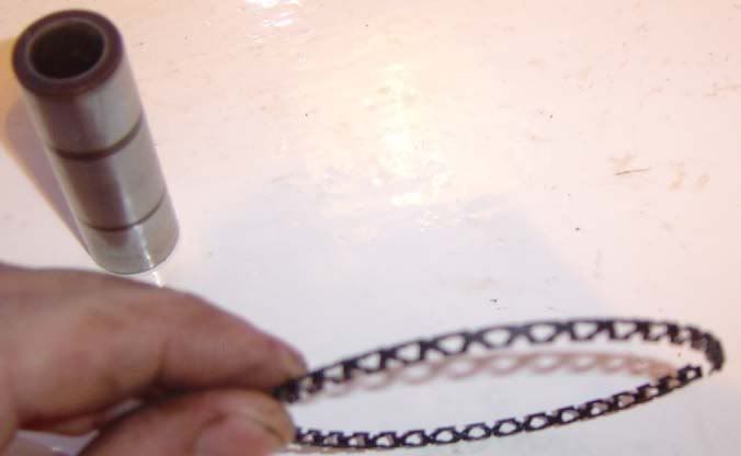
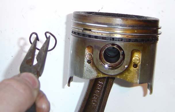
The oil scraper ring is designed to slide over oil when the piston is travelling up the cylinder but then to retrieve all but fine layer of oil on the downward stroke. Oil is then forced down to the crank case by the scraper ring and can escape through a small hole in the piston. Note that the compression rings can also perform some oil control but it is principally the job of this third ring. The oil scraper ring consists of 3 parts as shown below:
You can see there are two rings similar to the compression rings (but smaller) which sandwich the scraper.

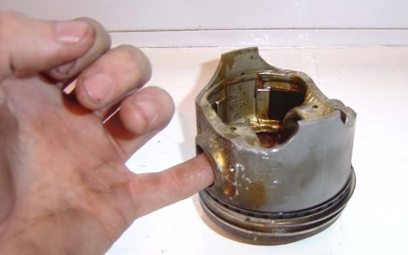
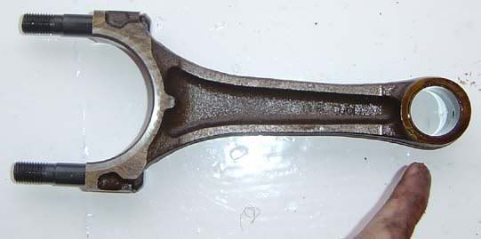
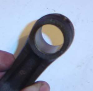
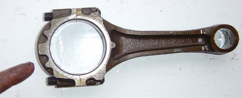
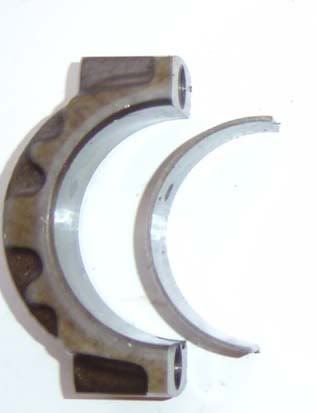
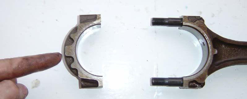
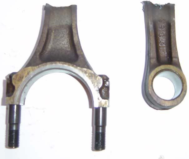
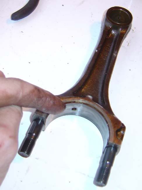
") of the rod which is where the rod bolts to the crankshaft (on what is known as the ‘crank pin’
of the rod which is where the rod bolts to the crankshaft (on what is known as the ‘crank pin’