
Special thanks to Angelo (Yardarm1) because without his efforts on his own cylinder head I probably would have never gotten round to finishing this! I started this guide the best part of a year ago but couldn't find time to finish it. Angelo knocked up his own guide which spurred me into action - I've used some comments and pictures from his document in this to (hopefully) create a pretty comprehensive overview.
Also thanks to Kev who donated the engine for this guide, much appreciated as always
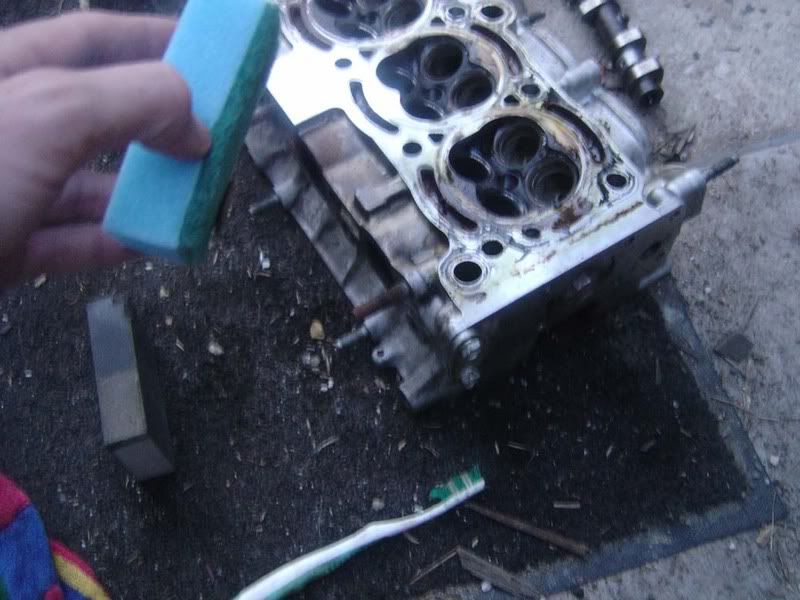
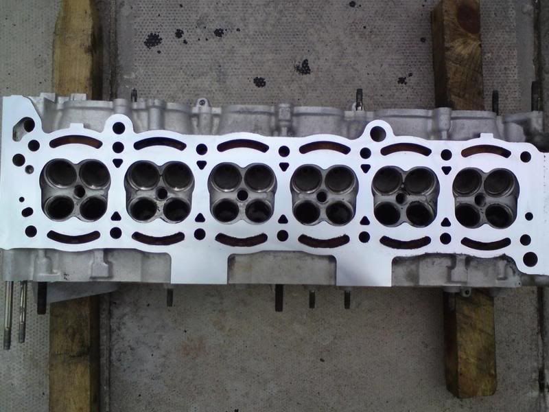
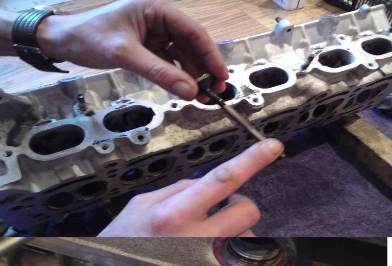
Step 1 - Once you've followed the guide for stripping a cylinder head you can start work on cleaning up and rebuilding it. Looking at the block from the underside with all the valves removed you'll probably find a fair amount of carbon build up and markings from gasket material, coolant etc. We need to remove all this material and dig back down to aluminium!
Start with a gasket scraper and remove the coa r s er (swear filter!) material from the head's surface. Don't press too hard and don't score the head's surface.
Oh, you'll have noticed the normal blue latex gloves have been substituted for a set of marigolds. Highly recommend you get a pair for £1.50, get the ones that don't say unsuitable for petroleum (duh!), and they will save you hours of smelling like a petrol pump!
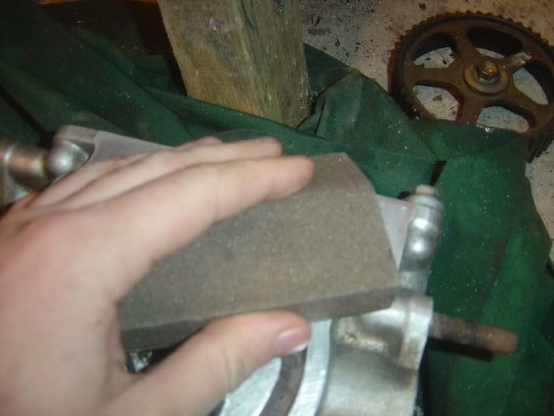
Step 2 - I find these Scotch pads very useful, they are soft enough to allow you to put pressure on the head without risk of scratching (unless you really try) and abrasive enough to get rid of gasket material. With a bit of patience you'll soon be able to bring back the head face to shiny clean metal.
Use a detergent to help with the cleaning and avoid scratching the head . I find a start with something like fairy liquid can be good for a surface clean (It's nice and thick when gasket scraping so gives a good layer of protection) then petrol is great for the finer detail. Lots of unleaded and a toothbrush
and you'll get instant results as shown!
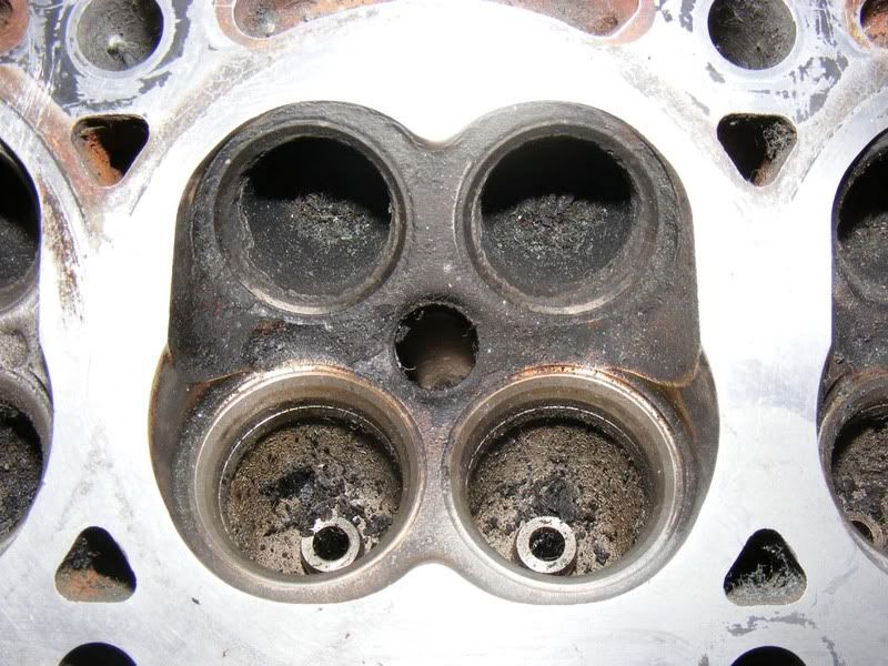
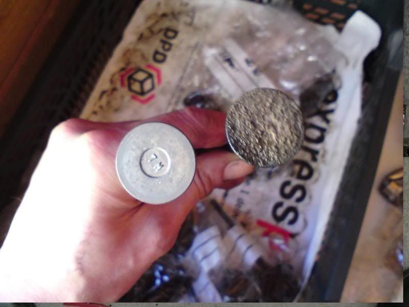
Step 3 - Look over the face of the head and make note of any pitting and scores you find. Here are some I found in the head I was working on. If you've got pitting or scoring or just aren't happy doing this work yourself then hand the cylinder head over to a machine shop who will pressure test it, skim as required and return it all squeaky clean. (see picture 2)
The subject of skimming is up for debate, most people agree that skimming is a bad thing and Toyota don't recommend you take a great deal off the surface before scrapping the head. If it's badly bowed then skimming will not fix the problem (you end up with a flat head/block surface but the rest of the head is still skewed). Some recommend just bolting it down to bring it back to a good mating surface but others will only do this by skimming, read about it and make your own mind up.
To paraphrase Ed (Darket) : When the head is bowed (front to rear) then the torque of bolting the head back down will bring it true. When warped across the face (left to right) then its new head time.
I recommend you go through the cleaning phase anyway before you decide whether a machine shop is required
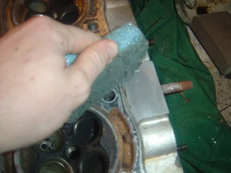
Step 4 - Use some very fine grit sandpaper for any real stubborn areas on the head where you can't get through the dirt but again, don't apply too much pressure and scratch the surface.
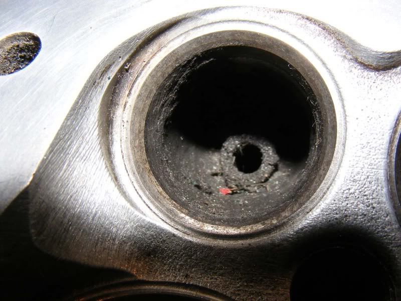
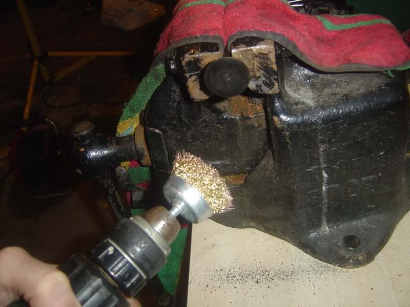
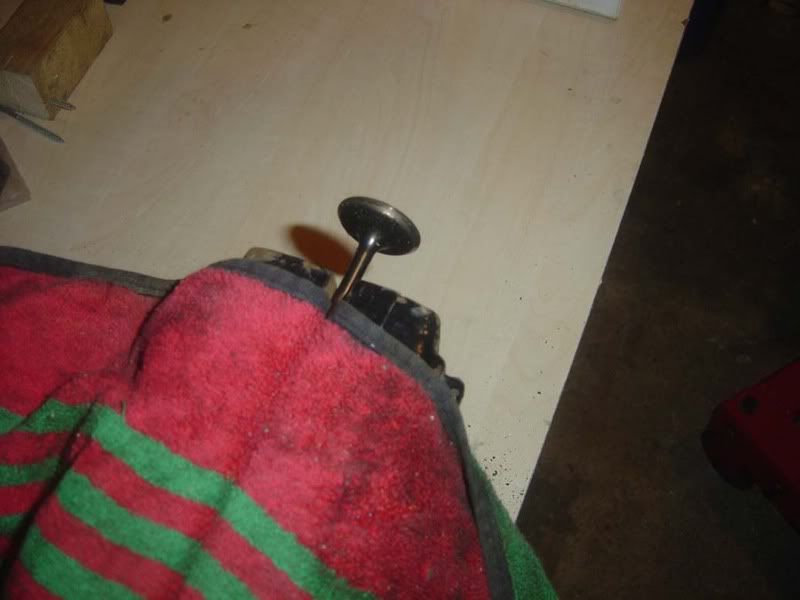
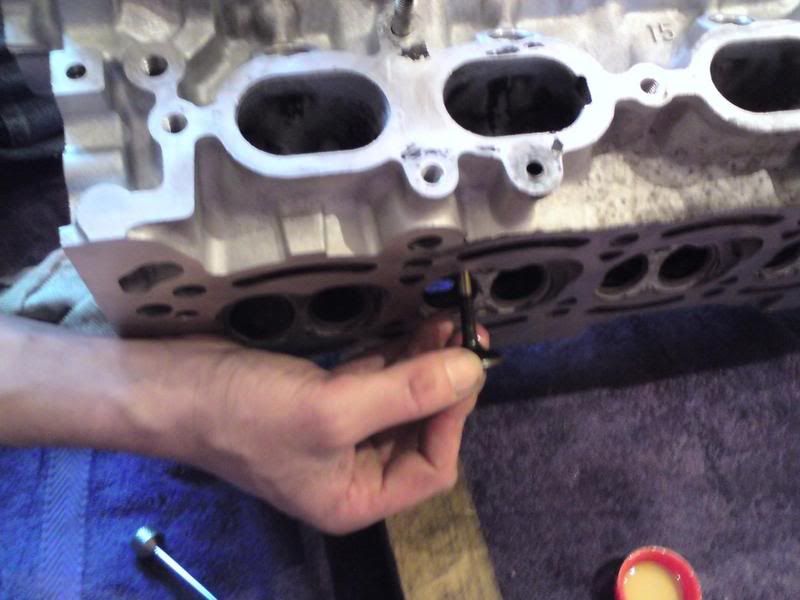
Step 5 - Once you've cleaned up the main surface where the head seals against the block you can move onto the combustion chamber in the head. A wire brush and variable speed drill will allow you to quickly cut through the carbon deposits. When doing this be extra careful the wire doesn't spin out and hit the surface of the head. Steel brushes don't lose their bristles as easily as brass so can be safer but whatever you use protect your eyes.
I've included a couple of before and after pictures as well

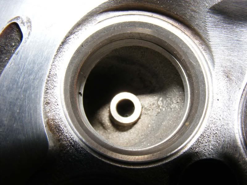
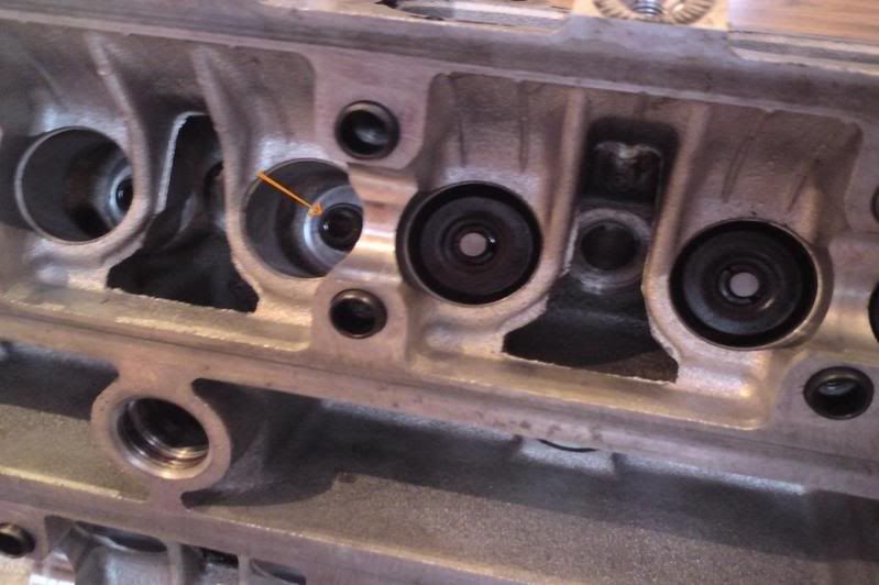
Step 6 - You'll quickly take off the majority of the black stuff and find some metal work underneath. You can try and clean out some of the carbon behind the valve seats too at this stage. Be careful on the valve seats, wire wool is recommended to clean these up
Step 7 - Repeat for all 6 cylinders
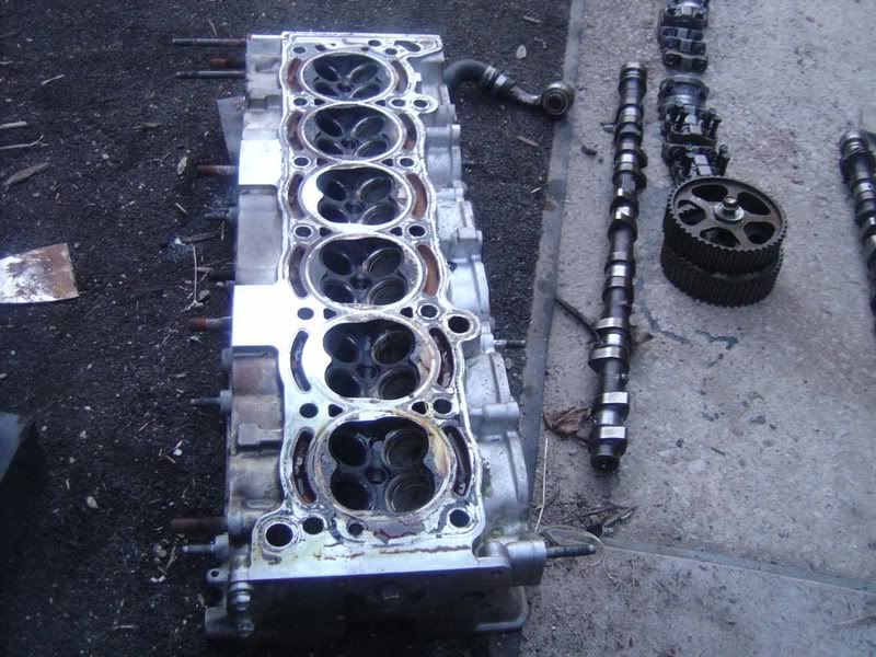
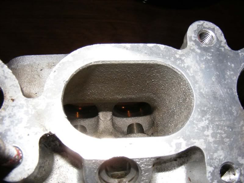
Step 8 - Once you've got a generally clean cylinder head start to really go to town on cleaning it. We've removed all surface build up at this stage and cleaned down to a good metal surface all over. We still have a lot of dirt to remove so grab your petrol and toothbrush again ...
Don't forget to the inlet and exhaust tracts too
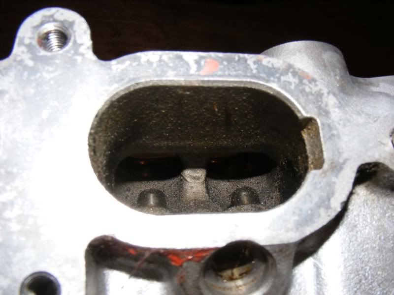
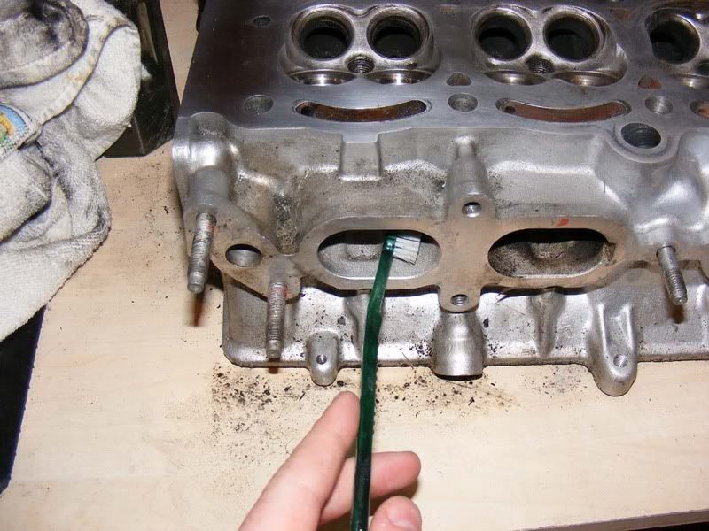
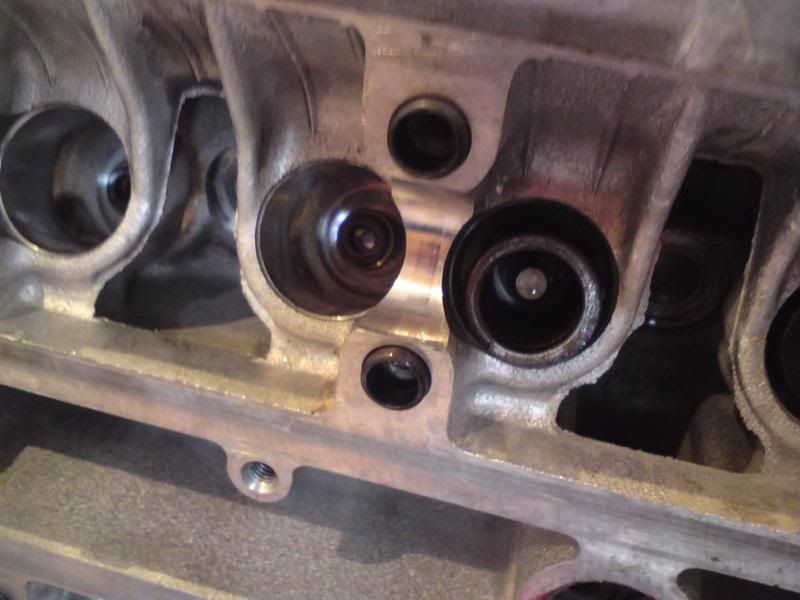
Step 9 - Really scrub the valve seats with the soft brush and remove any carbon to reveal the state of the metal beneath so we can later assess if there is too much pitting etc.
Step 10 - My 'deep clean' Is done with
- Lots of dousing and brushing with a soft brush and petrol
- A good scrub with a sotch pad
- Thorough wipe with a towel
Then more of the same (liberally using the fuel) until it's a very clean surface. The good thing about the fuel is that it evaporates so will leave no traces behind
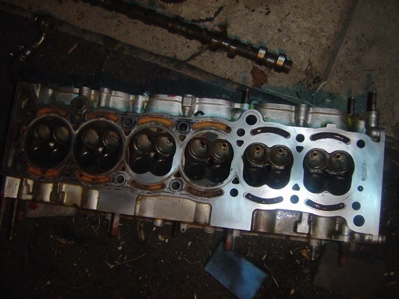
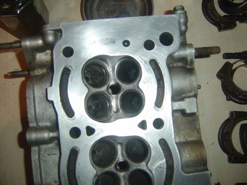
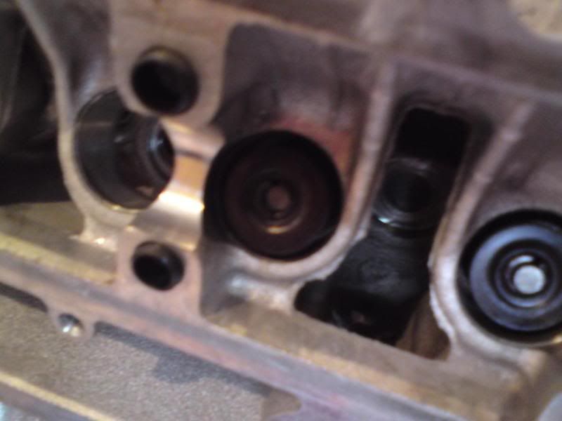
Step 11 - Clean up the outer parts of the block too, you don't want dirt anywhere on the head. It takes a few minutes with toothbrush and petrol to clean up the surface edges to a nice finish. These picture shows the difference it makes
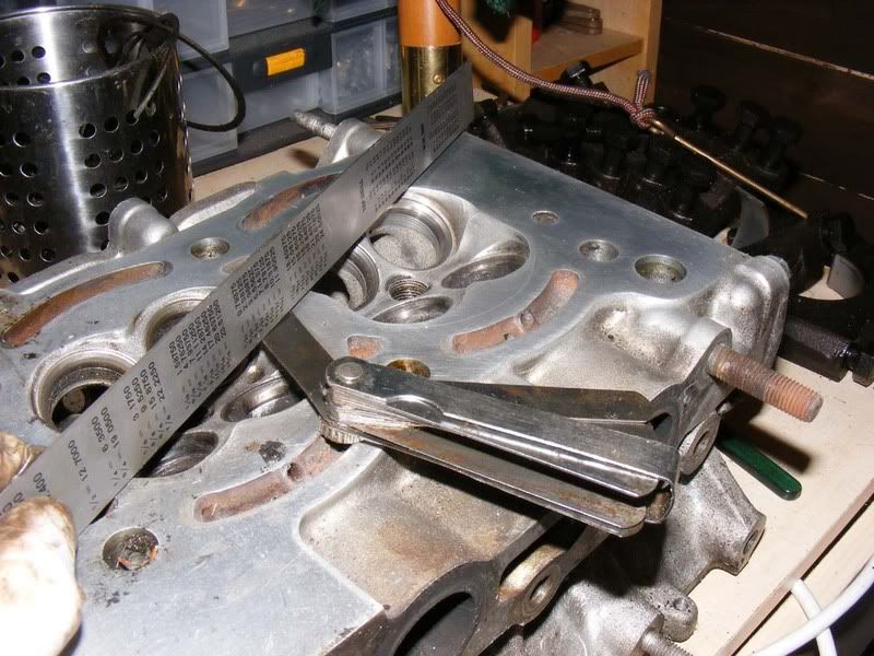
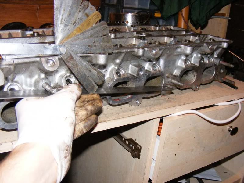
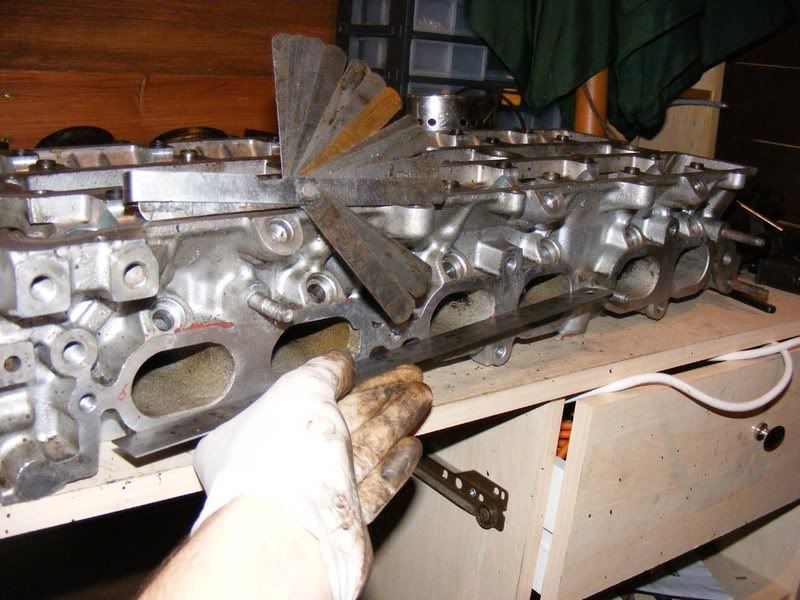
Step 12 - Once everything is spotlessly clean you can start to evaluate the condition of the head, is it flat, is it pitted, does it need a skim, can it have one etc. We'll start by measuring the surface to see how flat it is. To do this you'll need a straight edge and some feeler gauges.
Lay the straight edge across the head and slide the feeler gauge underneath the straight edge at various points to determine the warpage. 0.10mm is the recommended maximum allowed
You will want to do this end to end (front to back) across the head and also diagonally in both directions. Also do the same for the intake/exhaust manifolds. 0.10mm is the maximum recommended warpage from Toyota before a replacement is needed.
Note: I didn't have a precision straight edge to hand so just showed the principle with a small steel rule, you will need the real thing!
Step 13 - If you do need to go to a machine shop then you need to be able to tell them your requirements. Generally speaking your options are
1. If you're building a stock engine then you could use a standard gasket with standard bolts from Toyota - If you use standard bolts don't torque to the recommended 54ftl/lbs, go for 72
2. For a little extra peace of mind you could go for a standard gasket with ARP bolts (or even better ARP studs).
3. For performance applications you want to consider a metal head gasket (MHG). This requires a greater roughness average (RA) rating and you should follow the recommendation for your gasket - typically around 50 RA. Make sure your machine shop know your requirements here. You should go for ARP studs for high performance applications
If you do have the head skimmed, remember to take the timing belt cover to the machine shop too!
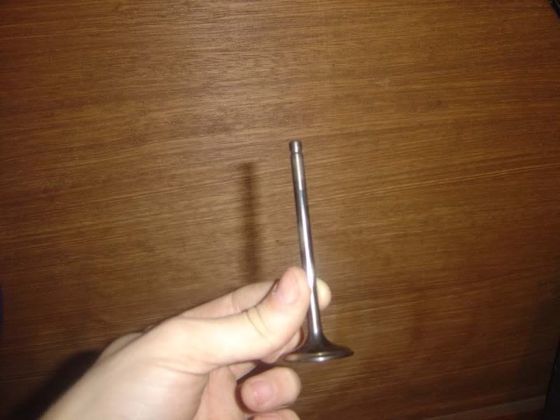
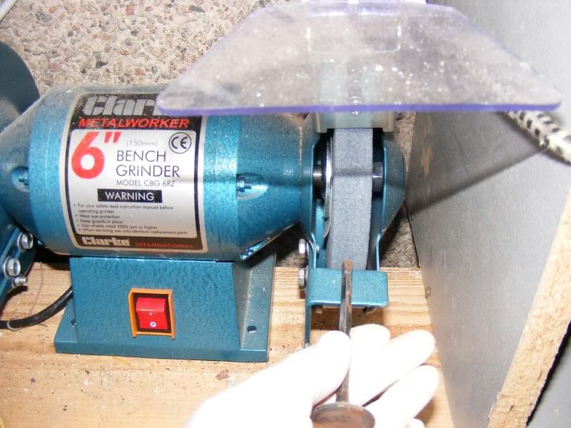
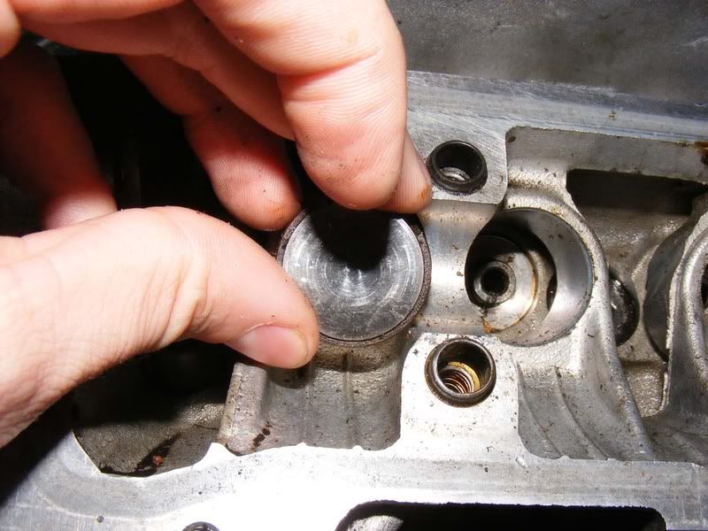
Step 14 - Once you've cleaned and assessed the head (if necessary sourced a replacement) you can move onto the valves. You can clean these up using a number of methods e.g. locking in a drill, using a gasket scraper to chip away etc but I've shown my preferred approach. Start by gripping the valve in a vice, I use a towel to protect the stem
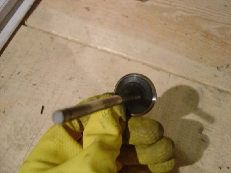
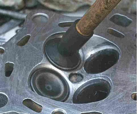
As well as the valve, check the seat in the head. The second picture shows an inlet valve seat and the third picture and exhaust valve seat.
The exhaust valves tend to be a problem, if you can't clear the pitting with the wire brush then they may need to be re cut so you can get yourself a 3/5 angle valve job and have them reseated (job for a machine shop unless you have the right tools)
Step 15 - With the valve locked in place you can now use a wire brush to cut through all the carbon build up
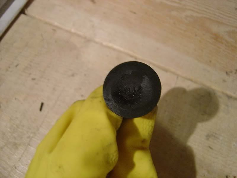
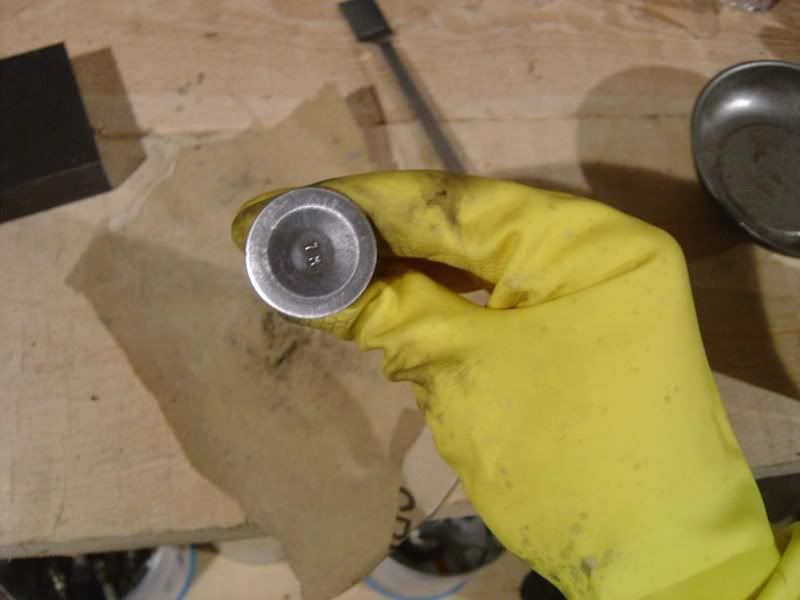
Step 16 - Concentrate on cleaning the head of the valve and be careful around the valve face (the bit that seats in the head and forms the seal). Clean each valve up so it looks something like these:
Step 17 - You should inspect the valve guides while the valves are out using a caliper gauge. Although you can change these yourself I would recommend leaving this job to the machine shop. If you do want to tackle it yourself then the TSRM has all the info you need
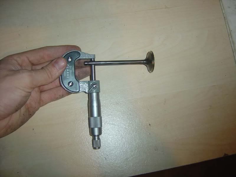
Step 18 - Check each valve with a micrometer along the stem in several places to ensure it is within spec:
Intake 5.970 - 5.985 mm
Exhaust 5.965 - 5.980 mm
If you are outside these specifications then consider a nice set of aftermarket valves (or replace for stock if you like!)
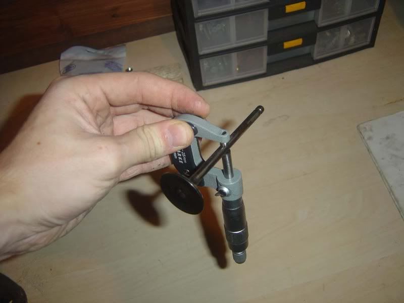
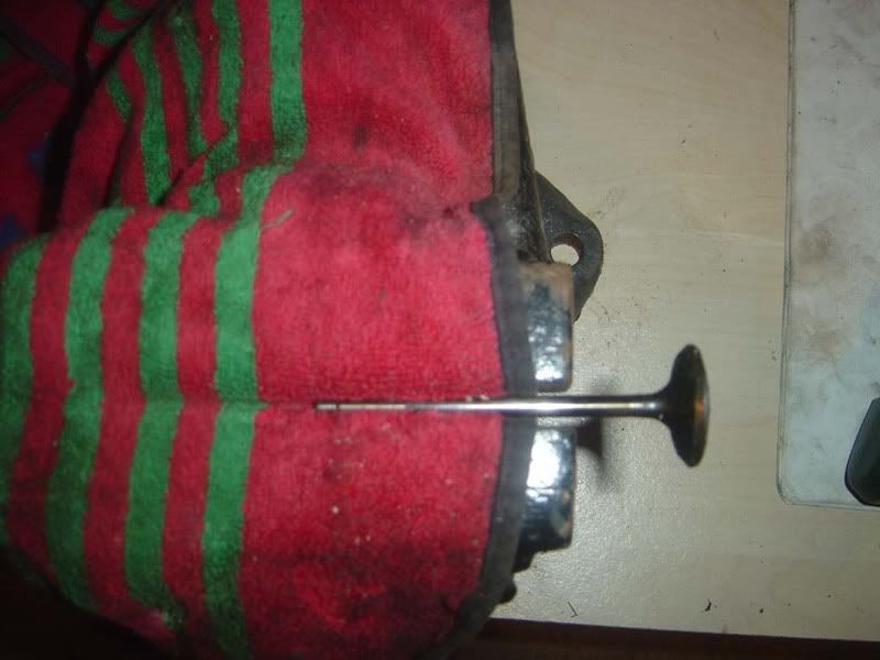
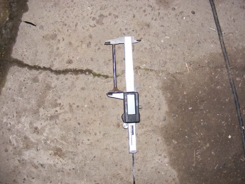
Step 19 - The length of the valve should be checked too. The tip of the stem can wear where the bucket acts on the valve. This isn't usually a problem but check the length (from the tip to the face) and if it is less than 97.75mm replace the valve. If necessary, resurface the tip of the valve (picture 2)
Step 20 - Once you have ascertained whether the valves are in good shape and the seats are suitable you can grind in the valves with the seat. To do this, apply a smear of fine grinding paste (not c-o-a-r-s-e, apologies for spacing - darned swear filter!) to the valve and use a valve grinding tool (basically a sucker that sticks to the valve and a piece of wood or drill attachment to spin it but make sure you go back and forth). Rotate the valve back and forth with light pressure
Step 21 - When working on the head after it has been machined and/or cleaned up, standing it on wooden blocks is a good idea to prevent damage.
On to replacing the valve stem oil seals is a nice easy job, simply dip them in oil then firmly push them down over the valve guides. This can be achieved with a 10mm 12-point socket. Push firmly down but there should be relatively little resistance if lined up properly
It's almost always worth doing them while the head is off. If you're burning oil then this (along with piston rings and turbo seals) is one of the likely suspects.
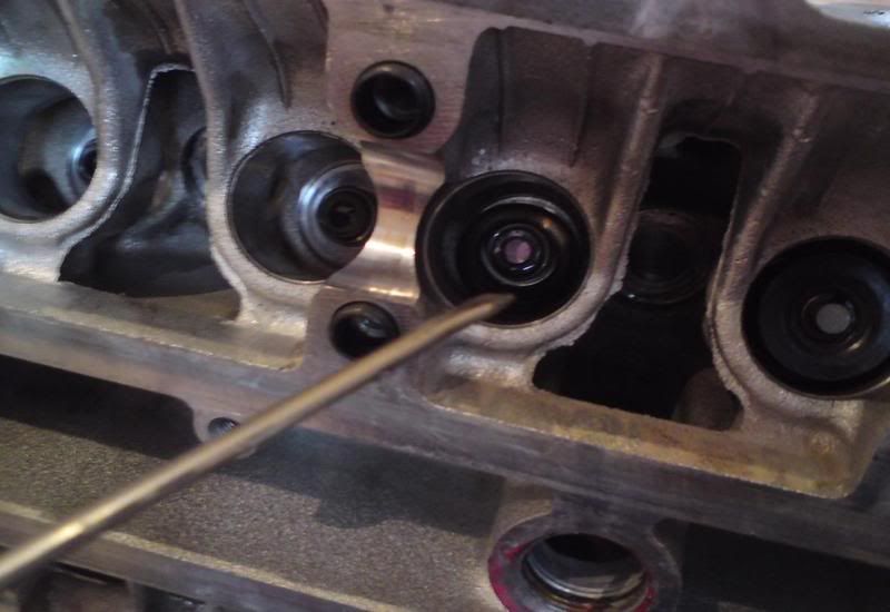
Step 22 - Once you've got the seals in place you can drop the spring seat in over the seal/stem and push down with a screwdriver.
Step 23 - Lubricate the valve stem (picture 1) then insert from the underside of the cylinder head (picture 2)
Step 24 - Drop the valve spring onto the spring seat and make sure it sits properly in place
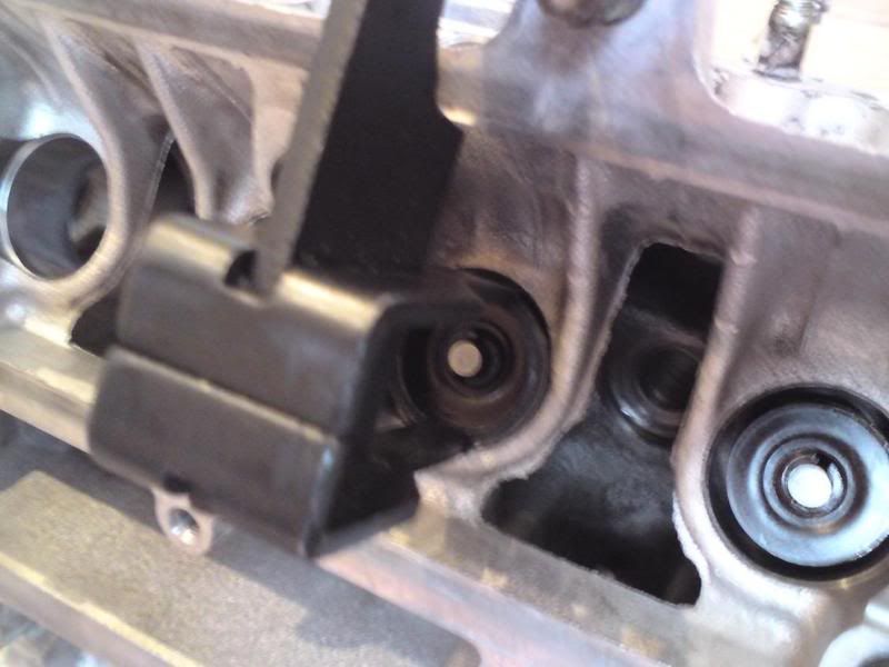
Step 25 - With the spring in place you can drop the retainer on and pop the 2 collets in line with the valve. A dab of grease will help the collets stay in place
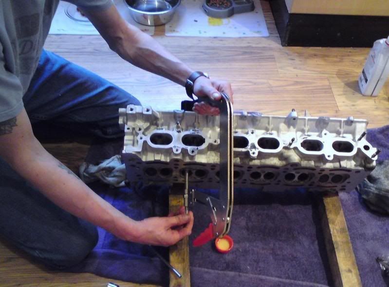
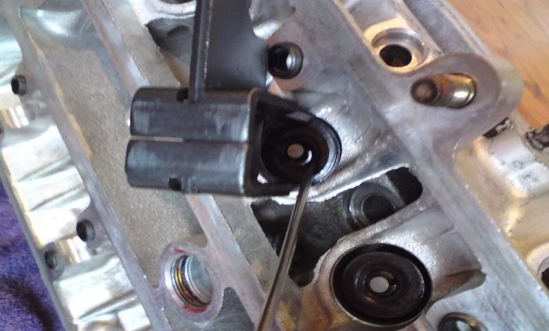
Step 26 - You will need a large valve spring compressor to work on the Supra head and some modification may be required to make it fit properly. Be very careful to not damage the head when performing this task!
1. Make sure you seat the valve spring compressor on the valve head correctly
2. Ensure the other end sits squarely on the spring retainer before you start compressing in earnest
3. Gradually apply pressure to the spring whilst checking the spring compressor hasn't moved out of square with the valve or retainer. Check that the head isn't being marked (around the where the bucket sits or the combustion chamber) as you compress it
4. When the spring is compressed, the collets should fit neatly into their grooves in the valve stem
5. Release the pressure on the spring compressor and move onto the next valve. Take your time and have some patience here, a mistake is costly. You may find a flatblade screwdriver is useful for lining the collets up. Lightly tap the valve stem to ensure the collets are seated
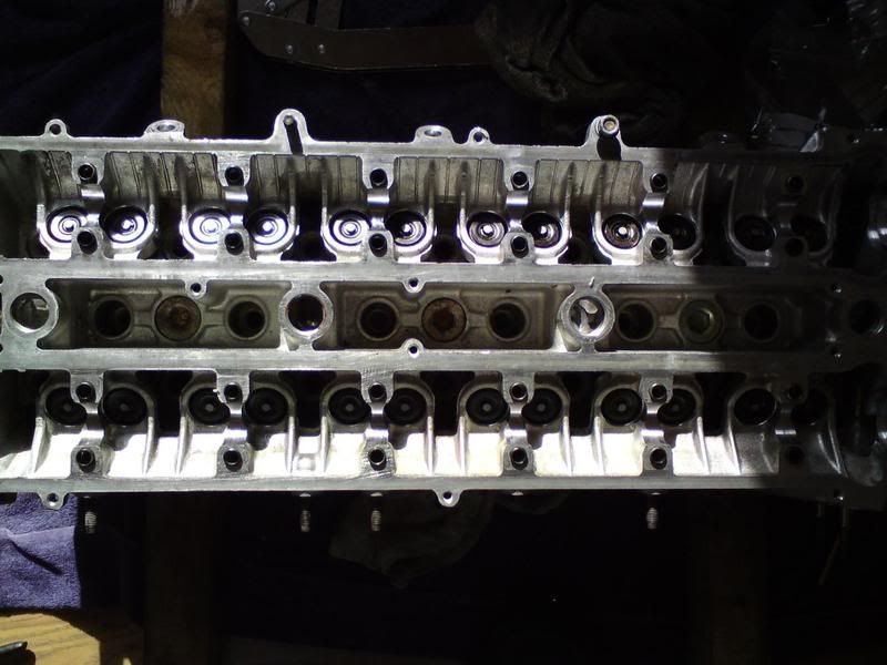
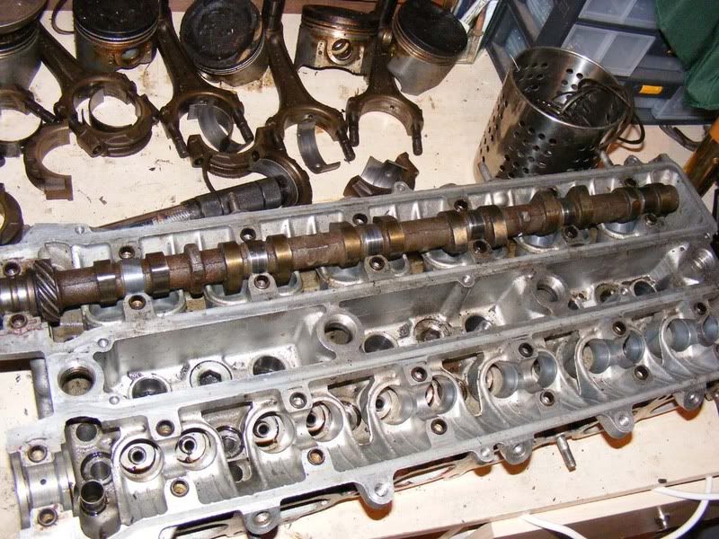
Step 27 - Once you've done this 24 times you should have a head like this:
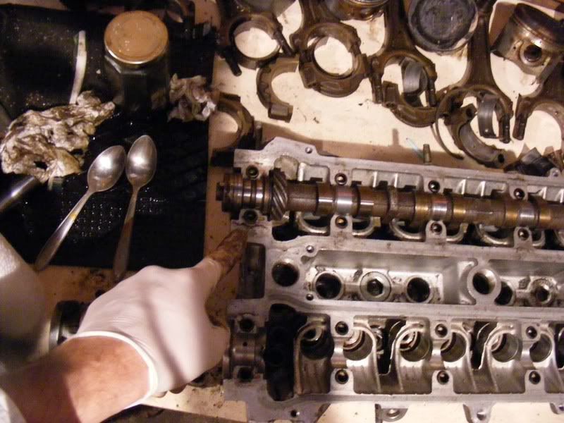
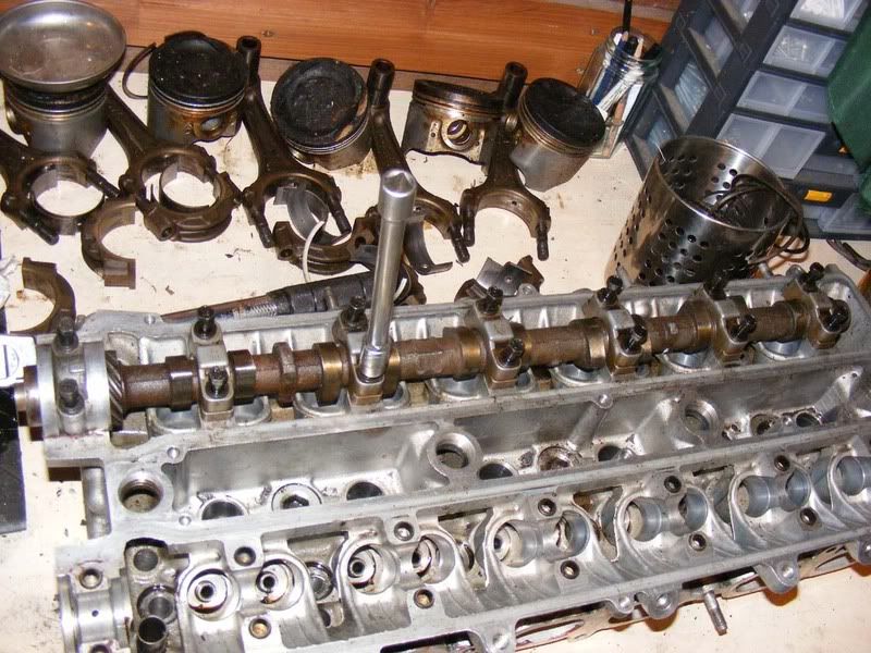
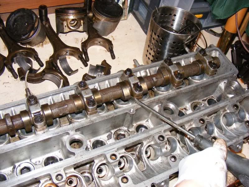
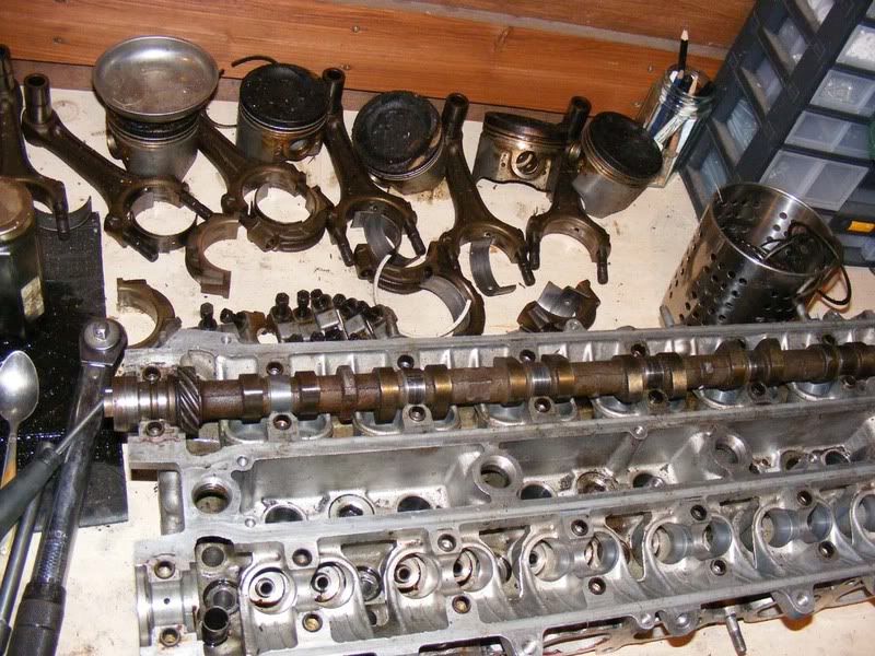
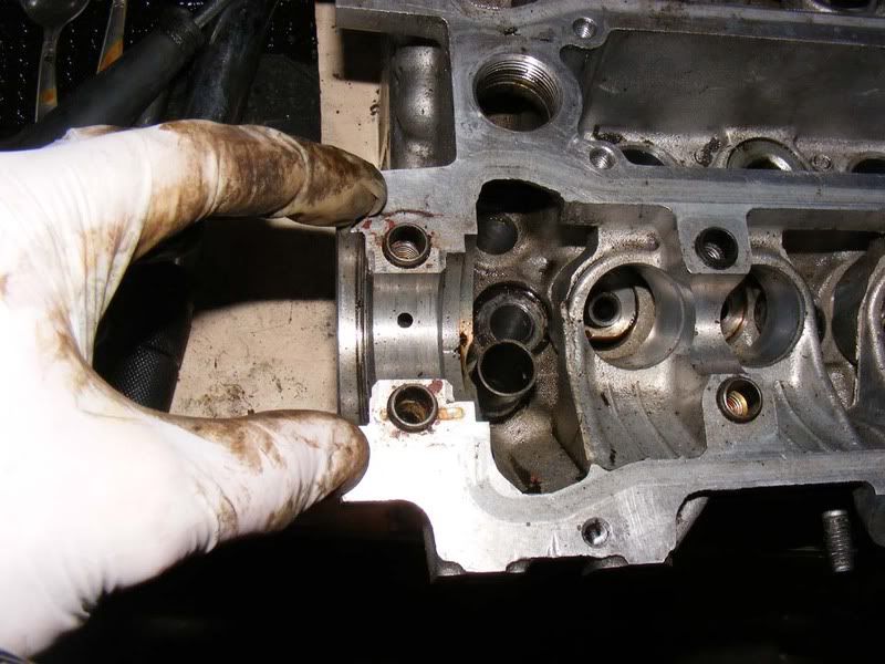
Step 28 - On to the camshafts next, clean up the cam caps
Step 29 - Also so the shafts themselves, pay particular attention to the bearing surfaces (the shiny metal circles that go under the cam caps)
Step 30 - Clean up the head again to make sure there's no dirt/dust on the bearing surface
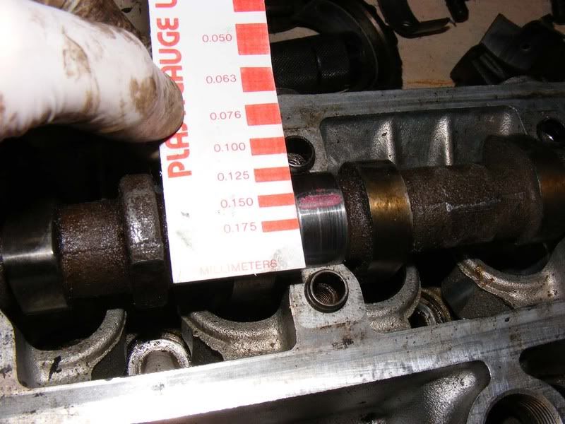
Step 31 - Lay the cam shaft on V blocks so that you can spin it freely and measure the circle runout of the middle journal. This can be a maximum of 0.03mm before you should change the shaft.
Step 32 - Use a micrometer to measure the journals (shown in the picture) and the cam lobes (the pointy bit!). The permissible values are:
1. Typically you should find 38.35mm for the cam lobes
2. The minimum value is 38.00mm for the lobes (if you get less than this, replace the shaft)
3. For the journals you should find between 26.949 and 26.965 mm for number 1 (the big one)
4. For journals 2-7 26.888 to 26.975 is the acceptable range. If you get smaller then a new camshaft is required
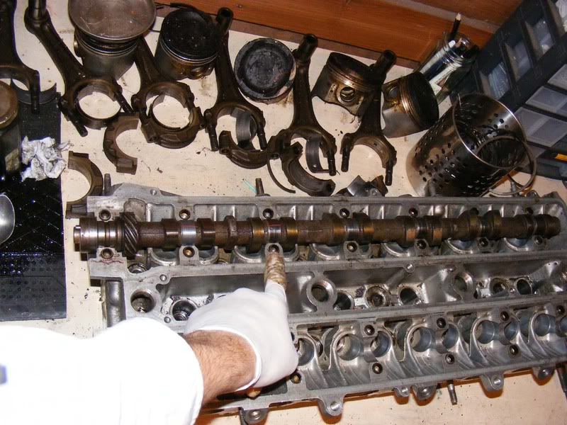
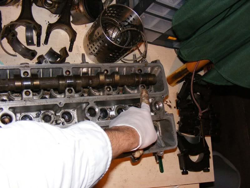
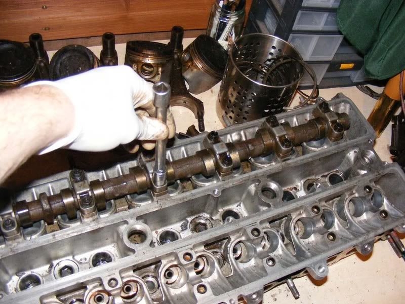
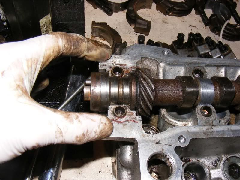
Step 33 - Once you have verified the shaft is usable, lay it onto the cylinder head. I'm going to show you the exhaust side but it's exactly the same for the inlet. Note it is laid in dry, no oil or assembly lube should be used when measuring the clearances
Step 34 - You will need some plastigauge. These are small strands that you cut to size and use to measure a bearing clearance. Basically it crushes in a repeatable manner and the expansion of the plastigauge will tell you the clearance between two surfaces. It's a few quid but should last you a long while as long as you keep it stored in a dry place.
It should come with a card so you can determine the clearance after pressurising the plastigauge.
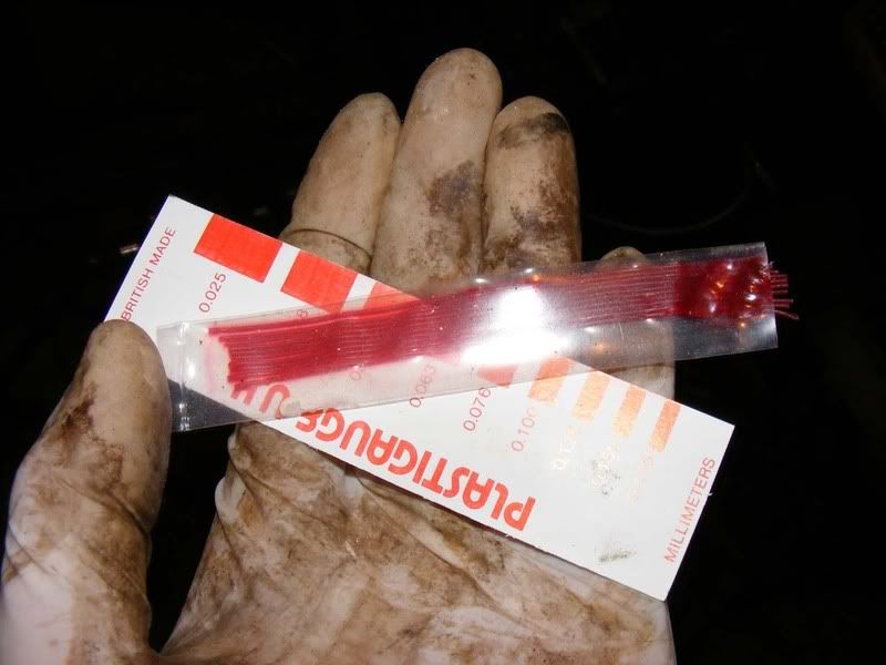
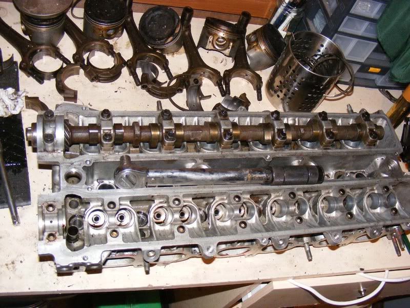
Step 35 - Lay strips of plastigauge laterally along each of the camshaft journals as shown
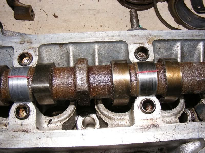
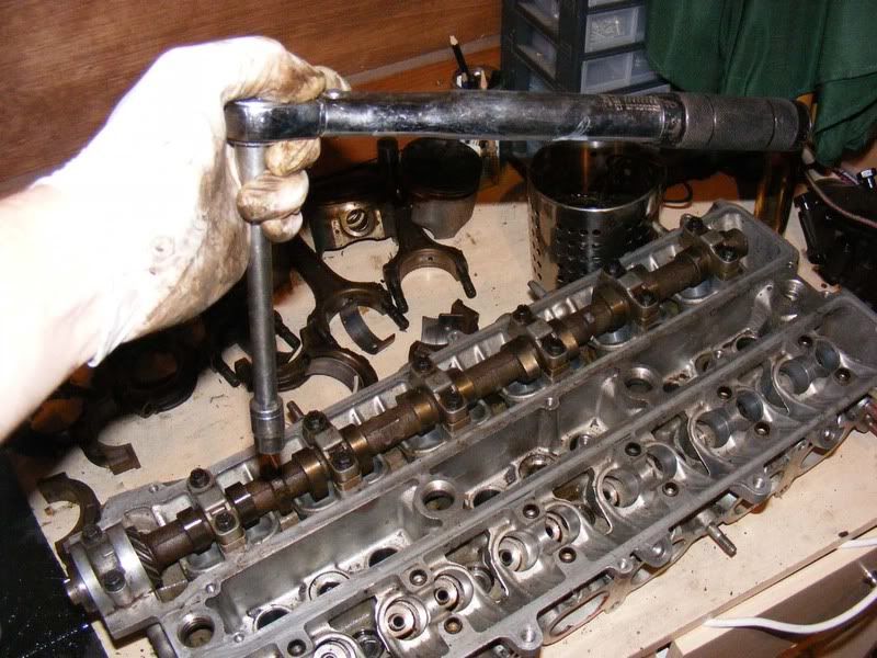
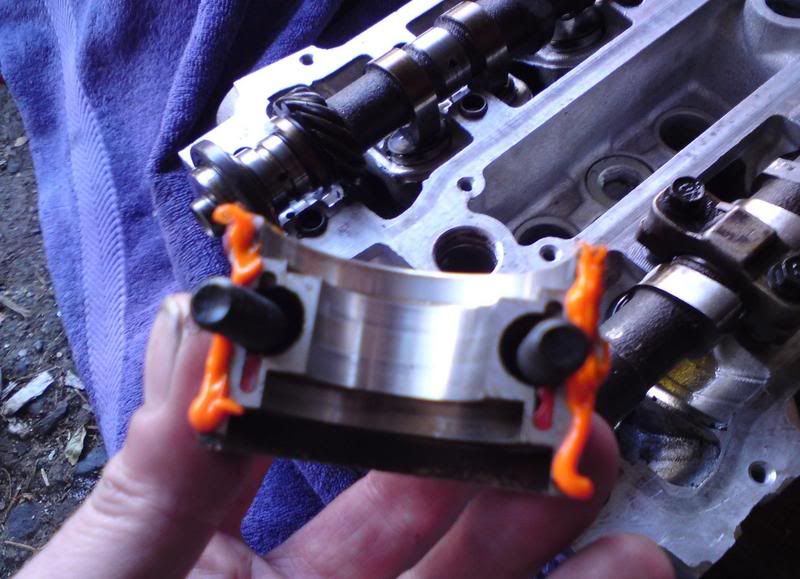
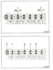
step 36 - Place the bearing caps along the shaft and loosely tighten them in the order shown (7614352). Don't forget to have the arrow facing towards the front of the engine and the correct numbers 1-7 from front to back.
Step 37 - Be sure to tighten the bolts in stages and don't torque up one side then the other of a cap, gradual tightening is required. Once they are finger tight you can torque them down to 14 ft/lbs (picture 2)
Step 38 - Once you've done all 7 caps you can undo all your hard work! Make sure you don't rotate the camshaft at all when the plastigauge is in place or you will get a false reading.
Step 39 - Remove the cam caps in the order shown in the first picture. Crack each nut off 1/4 turn then work round removing them in stages
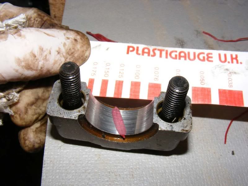
Step 40 - Measure the plastigauge at its widest point to determine the clearances. These should be 0.035-0.072 for cap #1 and 0.025-0.093mm for caps 2-7 on most vehicles. Anything over 0.13mm is too great then the head or the camshaft will need replacing.
The first picture is a bit misleading, the 0.125 reading should have been shown rather than 0.150, these were just within spec. The second picture shows a piece of plastigauge that stuck to the cap which clearly hits 0.125
Step 41 - Now clean off all trace of the plastigauge from the camshaft. This should be achieved with a fingernail or a tissue/cloth, don't use a screwdriver or you might score the bearing surface of the camshaft
Step 42 - Round 2, go through and torque all the caps up once again in the order shown in step 36 (no plastigauge this time)
Step 43 - Use a flatblade screwdriver against a cam lobe to ease it over to the back of the head (you probably won't feel it move much/at all but it will have)
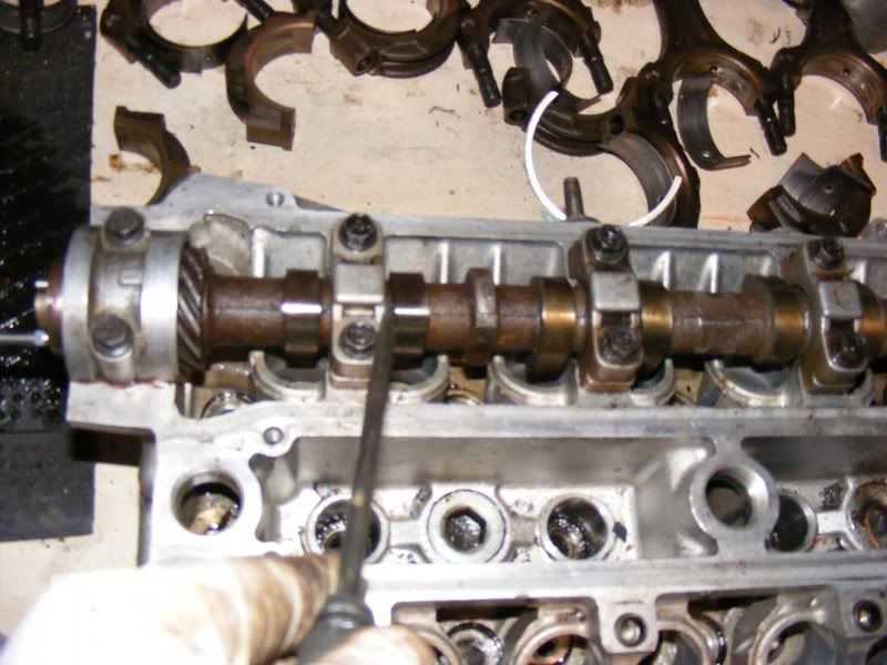
Step 44 - Place your dial gauge on the end of the camshaft and zero it.
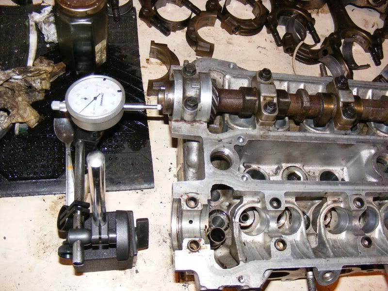
Step 45 - Now lever the shaft the other way towards the front of the engine (again you should feel little/no movement)
Step 46 - Check your dial gauge and you should find that the thrust clearance (that's what you just measured) is between 0.08 and 0.19mm. Any more than 0.30mm and the camshaft or head will need replacing. Mine was 0.08mm as shown
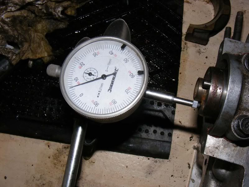
Step 47 - Remove all those caps again, don't worry this is the last time. Follow the order shown in step 39
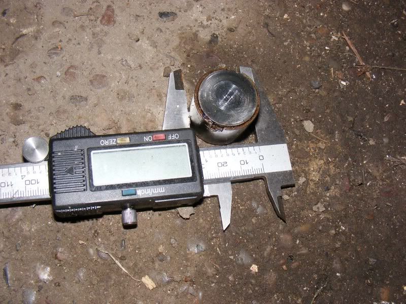
Step 48 - Ideally you should measure each bucket (valve lifter) across the diameter (picture shows a micrometer being used because I didn't have a vernier handy). Make sure it is between 27.975mm and 27.985mm. You should then check the internal diameter of the hole where the lifter is going to sit.
You subtract the diameter of the lifter from the internal diameter of the bore to get the oil clearance. This is typically 0.015-0.046mm but should be no more than 0.1mm. If greater than this the lifter or head should be replaced.
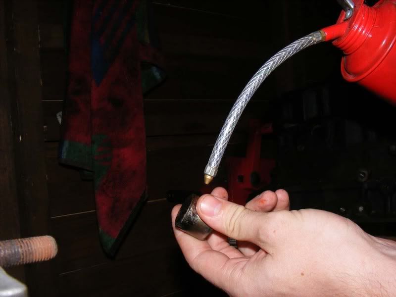
Step 49 - Lubricate each bucket as you install it, twist as you drop it into place on the valve
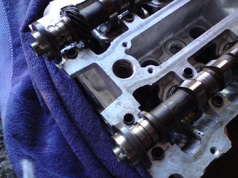
Step 50 - Once you've got all the buckets in place you can put the camshafts back on. When installing the camshafts (and any bearing surface) apply plenty of assembly lube. You can use engine oil but proper lube gives better protection and lasts longer so handy if you are doing the build over several days/weeks.
Make sure you install the correct caps in the correct order (1-7 where 1 is at the front of the car, E for exhaust or I for inlet, arrow pointing towards the front of the engine)
A small line of sealant should be placed on the #1 bearing cap or either side of it on the head itself in the positions shown (exhaust and inlet are shown and there should be a line where the finger and thumb are)
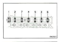
Pay special attention to the torque sequence for final camshaft fitment. This is different to earlier when sizing the bearings. You start by torquing 3 and 7 in stages then move onto the other caps in the sequence 5-4-6-2-1 as shown in the diagram from the TSRM
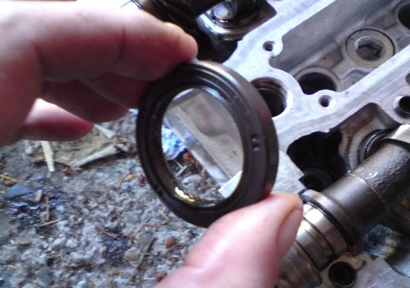
Step 51 - Lubricate the camshaft oil seals with engine oil and install before fitting the caps for simplicity (although you can do it afterwards if need be with a hammer)
Step 52 - Before fitting the inlet and exhaust manifolds you should run the straight edge across them to ensure they are flat in the same way as the cylinder head. This isn't usually a problem area but is worth checking. 0.10mm for the intake manifold/chamber and 0.50mm for the exhaust manifold.
More importantly, helicoil the threads on the exhaust side, these are invariably a trouble spot. You can use an M10 x 1.25 v-coil kit (about £25) or if you have the time/inclination go for standard M10 x 1.50 inserts to get rid of the abnormal thread pitch.
That's just about all there is to say really, from this stage you put the EGR (if you have it) and manifolds back on then move on to rebuilding the bottom end if you need to (there will be another guide at some stage) and then bolt the two together. The big tip is to keep everything in order and cleanliness really is required. Take the time to clean and lubricate everything so your newly built head will last you.
Additional points:
When working on the head, make sure you check out all the coolant paths and replace as required. One area to check is the water union at the back of the head.
Some scoring on the cams is normal but it's rare to find it trashed. I guess this is a judgement call you have to make. If there is any doubt about anything like that then ask your machine shop or post on here. If you can feel significant score marks in any bearing surface then you need to address it.
As for measuring for the cams - the plastigauge will tell you if the clearance is under/over if that's what you mean. If you've got clearance issues here it gets very costly to line bore and rebush them so people generally source a replacement head
To clarify on the RA recommendation of 50 - this is 0.50 micrometers (approximately 21 microinches, there are 0.0254 micrometers in a microinch).
Also thanks to Kev who donated the engine for this guide, much appreciated as always
Step 1 - Once you've followed the guide for stripping a cylinder head you can start work on cleaning up and rebuilding it. Looking at the block from the underside with all the valves removed you'll probably find a fair amount of carbon build up and markings from gasket material, coolant etc. We need to remove all this material and dig back down to aluminium!
Start with a gasket scraper and remove the coa r s er (swear filter!) material from the head's surface. Don't press too hard and don't score the head's surface.
Oh, you'll have noticed the normal blue latex gloves have been substituted for a set of marigolds. Highly recommend you get a pair for £1.50, get the ones that don't say unsuitable for petroleum (duh!), and they will save you hours of smelling like a petrol pump!
Step 2 - I find these Scotch pads very useful, they are soft enough to allow you to put pressure on the head without risk of scratching (unless you really try) and abrasive enough to get rid of gasket material. With a bit of patience you'll soon be able to bring back the head face to shiny clean metal.
Use a detergent to help with the cleaning and avoid scratching the head . I find a start with something like fairy liquid can be good for a surface clean (It's nice and thick when gasket scraping so gives a good layer of protection) then petrol is great for the finer detail. Lots of unleaded and a toothbrush
and you'll get instant results as shown!
Step 3 - Look over the face of the head and make note of any pitting and scores you find. Here are some I found in the head I was working on. If you've got pitting or scoring or just aren't happy doing this work yourself then hand the cylinder head over to a machine shop who will pressure test it, skim as required and return it all squeaky clean. (see picture 2)
The subject of skimming is up for debate, most people agree that skimming is a bad thing and Toyota don't recommend you take a great deal off the surface before scrapping the head. If it's badly bowed then skimming will not fix the problem (you end up with a flat head/block surface but the rest of the head is still skewed). Some recommend just bolting it down to bring it back to a good mating surface but others will only do this by skimming, read about it and make your own mind up.
To paraphrase Ed (Darket) : When the head is bowed (front to rear) then the torque of bolting the head back down will bring it true. When warped across the face (left to right) then its new head time.
I recommend you go through the cleaning phase anyway before you decide whether a machine shop is required
Step 4 - Use some very fine grit sandpaper for any real stubborn areas on the head where you can't get through the dirt but again, don't apply too much pressure and scratch the surface.
Step 5 - Once you've cleaned up the main surface where the head seals against the block you can move onto the combustion chamber in the head. A wire brush and variable speed drill will allow you to quickly cut through the carbon deposits. When doing this be extra careful the wire doesn't spin out and hit the surface of the head. Steel brushes don't lose their bristles as easily as brass so can be safer but whatever you use protect your eyes.
I've included a couple of before and after pictures as well
Step 6 - You'll quickly take off the majority of the black stuff and find some metal work underneath. You can try and clean out some of the carbon behind the valve seats too at this stage. Be careful on the valve seats, wire wool is recommended to clean these up
Step 7 - Repeat for all 6 cylinders
Step 8 - Once you've got a generally clean cylinder head start to really go to town on cleaning it. We've removed all surface build up at this stage and cleaned down to a good metal surface all over. We still have a lot of dirt to remove so grab your petrol and toothbrush again ...
Don't forget to the inlet and exhaust tracts too
Step 9 - Really scrub the valve seats with the soft brush and remove any carbon to reveal the state of the metal beneath so we can later assess if there is too much pitting etc.
Step 10 - My 'deep clean' Is done with
- Lots of dousing and brushing with a soft brush and petrol
- A good scrub with a sotch pad
- Thorough wipe with a towel
Then more of the same (liberally using the fuel) until it's a very clean surface. The good thing about the fuel is that it evaporates so will leave no traces behind
Step 11 - Clean up the outer parts of the block too, you don't want dirt anywhere on the head. It takes a few minutes with toothbrush and petrol to clean up the surface edges to a nice finish. These picture shows the difference it makes
Step 12 - Once everything is spotlessly clean you can start to evaluate the condition of the head, is it flat, is it pitted, does it need a skim, can it have one etc. We'll start by measuring the surface to see how flat it is. To do this you'll need a straight edge and some feeler gauges.
Lay the straight edge across the head and slide the feeler gauge underneath the straight edge at various points to determine the warpage. 0.10mm is the recommended maximum allowed
You will want to do this end to end (front to back) across the head and also diagonally in both directions. Also do the same for the intake/exhaust manifolds. 0.10mm is the maximum recommended warpage from Toyota before a replacement is needed.
Note: I didn't have a precision straight edge to hand so just showed the principle with a small steel rule, you will need the real thing!
Step 13 - If you do need to go to a machine shop then you need to be able to tell them your requirements. Generally speaking your options are
1. If you're building a stock engine then you could use a standard gasket with standard bolts from Toyota - If you use standard bolts don't torque to the recommended 54ftl/lbs, go for 72
2. For a little extra peace of mind you could go for a standard gasket with ARP bolts (or even better ARP studs).
3. For performance applications you want to consider a metal head gasket (MHG). This requires a greater roughness average (RA) rating and you should follow the recommendation for your gasket - typically around 50 RA. Make sure your machine shop know your requirements here. You should go for ARP studs for high performance applications
If you do have the head skimmed, remember to take the timing belt cover to the machine shop too!
Step 14 - Once you've cleaned and assessed the head (if necessary sourced a replacement) you can move onto the valves. You can clean these up using a number of methods e.g. locking in a drill, using a gasket scraper to chip away etc but I've shown my preferred approach. Start by gripping the valve in a vice, I use a towel to protect the stem
As well as the valve, check the seat in the head. The second picture shows an inlet valve seat and the third picture and exhaust valve seat.
The exhaust valves tend to be a problem, if you can't clear the pitting with the wire brush then they may need to be re cut so you can get yourself a 3/5 angle valve job and have them reseated (job for a machine shop unless you have the right tools)
Step 15 - With the valve locked in place you can now use a wire brush to cut through all the carbon build up
Step 16 - Concentrate on cleaning the head of the valve and be careful around the valve face (the bit that seats in the head and forms the seal). Clean each valve up so it looks something like these:
Step 17 - You should inspect the valve guides while the valves are out using a caliper gauge. Although you can change these yourself I would recommend leaving this job to the machine shop. If you do want to tackle it yourself then the TSRM has all the info you need
Step 18 - Check each valve with a micrometer along the stem in several places to ensure it is within spec:
Intake 5.970 - 5.985 mm
Exhaust 5.965 - 5.980 mm
If you are outside these specifications then consider a nice set of aftermarket valves (or replace for stock if you like!)
Step 19 - The length of the valve should be checked too. The tip of the stem can wear where the bucket acts on the valve. This isn't usually a problem but check the length (from the tip to the face) and if it is less than 97.75mm replace the valve. If necessary, resurface the tip of the valve (picture 2)
Step 20 - Once you have ascertained whether the valves are in good shape and the seats are suitable you can grind in the valves with the seat. To do this, apply a smear of fine grinding paste (not c-o-a-r-s-e, apologies for spacing - darned swear filter!) to the valve and use a valve grinding tool (basically a sucker that sticks to the valve and a piece of wood or drill attachment to spin it but make sure you go back and forth). Rotate the valve back and forth with light pressure
Step 21 - When working on the head after it has been machined and/or cleaned up, standing it on wooden blocks is a good idea to prevent damage.
On to replacing the valve stem oil seals is a nice easy job, simply dip them in oil then firmly push them down over the valve guides. This can be achieved with a 10mm 12-point socket. Push firmly down but there should be relatively little resistance if lined up properly
It's almost always worth doing them while the head is off. If you're burning oil then this (along with piston rings and turbo seals) is one of the likely suspects.
Step 22 - Once you've got the seals in place you can drop the spring seat in over the seal/stem and push down with a screwdriver.
Step 23 - Lubricate the valve stem (picture 1) then insert from the underside of the cylinder head (picture 2)
Step 24 - Drop the valve spring onto the spring seat and make sure it sits properly in place
Step 25 - With the spring in place you can drop the retainer on and pop the 2 collets in line with the valve. A dab of grease will help the collets stay in place
Step 26 - You will need a large valve spring compressor to work on the Supra head and some modification may be required to make it fit properly. Be very careful to not damage the head when performing this task!
1. Make sure you seat the valve spring compressor on the valve head correctly
2. Ensure the other end sits squarely on the spring retainer before you start compressing in earnest
3. Gradually apply pressure to the spring whilst checking the spring compressor hasn't moved out of square with the valve or retainer. Check that the head isn't being marked (around the where the bucket sits or the combustion chamber) as you compress it
4. When the spring is compressed, the collets should fit neatly into their grooves in the valve stem
5. Release the pressure on the spring compressor and move onto the next valve. Take your time and have some patience here, a mistake is costly. You may find a flatblade screwdriver is useful for lining the collets up. Lightly tap the valve stem to ensure the collets are seated
Step 27 - Once you've done this 24 times you should have a head like this:
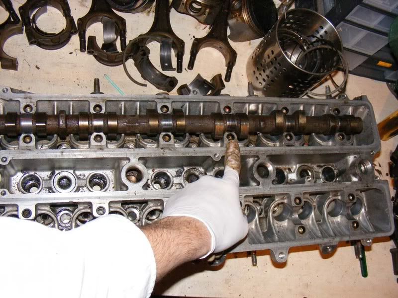
Step 28 - On to the camshafts next, clean up the cam caps
Step 29 - Also so the shafts themselves, pay particular attention to the bearing surfaces (the shiny metal circles that go under the cam caps)
Step 30 - Clean up the head again to make sure there's no dirt/dust on the bearing surface
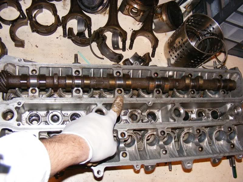
Step 31 - Lay the cam shaft on V blocks so that you can spin it freely and measure the circle runout of the middle journal. This can be a maximum of 0.03mm before you should change the shaft.
Step 32 - Use a micrometer to measure the journals (shown in the picture) and the cam lobes (the pointy bit!). The permissible values are:
1. Typically you should find 38.35mm for the cam lobes
2. The minimum value is 38.00mm for the lobes (if you get less than this, replace the shaft)
3. For the journals you should find between 26.949 and 26.965 mm for number 1 (the big one)
4. For journals 2-7 26.888 to 26.975 is the acceptable range. If you get smaller then a new camshaft is required
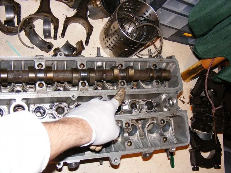
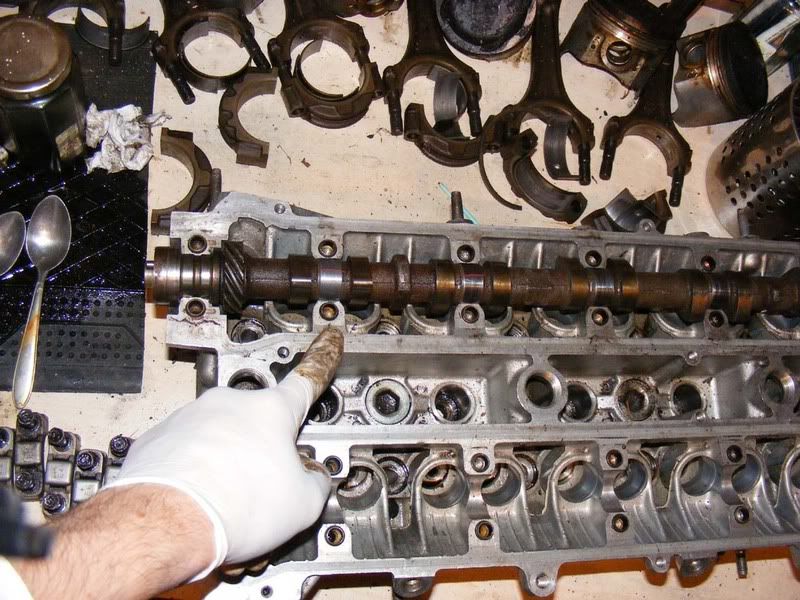
Step 33 - Once you have verified the shaft is usable, lay it onto the cylinder head. I'm going to show you the exhaust side but it's exactly the same for the inlet. Note it is laid in dry, no oil or assembly lube should be used when measuring the clearances
Step 34 - You will need some plastigauge. These are small strands that you cut to size and use to measure a bearing clearance. Basically it crushes in a repeatable manner and the expansion of the plastigauge will tell you the clearance between two surfaces. It's a few quid but should last you a long while as long as you keep it stored in a dry place.
It should come with a card so you can determine the clearance after pressurising the plastigauge.
Step 35 - Lay strips of plastigauge laterally along each of the camshaft journals as shown
step 36 - Place the bearing caps along the shaft and loosely tighten them in the order shown (7614352). Don't forget to have the arrow facing towards the front of the engine and the correct numbers 1-7 from front to back.
Step 37 - Be sure to tighten the bolts in stages and don't torque up one side then the other of a cap, gradual tightening is required. Once they are finger tight you can torque them down to 14 ft/lbs (picture 2)
Step 38 - Once you've done all 7 caps you can undo all your hard work! Make sure you don't rotate the camshaft at all when the plastigauge is in place or you will get a false reading.
Step 39 - Remove the cam caps in the order shown in the first picture. Crack each nut off 1/4 turn then work round removing them in stages
Step 40 - Measure the plastigauge at its widest point to determine the clearances. These should be 0.035-0.072 for cap #1 and 0.025-0.093mm for caps 2-7 on most vehicles. Anything over 0.13mm is too great then the head or the camshaft will need replacing.
The first picture is a bit misleading, the 0.125 reading should have been shown rather than 0.150, these were just within spec. The second picture shows a piece of plastigauge that stuck to the cap which clearly hits 0.125
Step 41 - Now clean off all trace of the plastigauge from the camshaft. This should be achieved with a fingernail or a tissue/cloth, don't use a screwdriver or you might score the bearing surface of the camshaft
Step 42 - Round 2, go through and torque all the caps up once again in the order shown in step 36 (no plastigauge this time)
Step 43 - Use a flatblade screwdriver against a cam lobe to ease it over to the back of the head (you probably won't feel it move much/at all but it will have)
Step 44 - Place your dial gauge on the end of the camshaft and zero it.
Step 45 - Now lever the shaft the other way towards the front of the engine (again you should feel little/no movement)
Step 46 - Check your dial gauge and you should find that the thrust clearance (that's what you just measured) is between 0.08 and 0.19mm. Any more than 0.30mm and the camshaft or head will need replacing. Mine was 0.08mm as shown
Step 47 - Remove all those caps again, don't worry this is the last time. Follow the order shown in step 39
Step 48 - Ideally you should measure each bucket (valve lifter) across the diameter (picture shows a micrometer being used because I didn't have a vernier handy). Make sure it is between 27.975mm and 27.985mm. You should then check the internal diameter of the hole where the lifter is going to sit.
You subtract the diameter of the lifter from the internal diameter of the bore to get the oil clearance. This is typically 0.015-0.046mm but should be no more than 0.1mm. If greater than this the lifter or head should be replaced.
Step 49 - Lubricate each bucket as you install it, twist as you drop it into place on the valve
Step 50 - Once you've got all the buckets in place you can put the camshafts back on. When installing the camshafts (and any bearing surface) apply plenty of assembly lube. You can use engine oil but proper lube gives better protection and lasts longer so handy if you are doing the build over several days/weeks.
Make sure you install the correct caps in the correct order (1-7 where 1 is at the front of the car, E for exhaust or I for inlet, arrow pointing towards the front of the engine)
A small line of sealant should be placed on the #1 bearing cap or either side of it on the head itself in the positions shown (exhaust and inlet are shown and there should be a line where the finger and thumb are)
Pay special attention to the torque sequence for final camshaft fitment. This is different to earlier when sizing the bearings. You start by torquing 3 and 7 in stages then move onto the other caps in the sequence 5-4-6-2-1 as shown in the diagram from the TSRM
Step 51 - Lubricate the camshaft oil seals with engine oil and install before fitting the caps for simplicity (although you can do it afterwards if need be with a hammer)
Step 52 - Before fitting the inlet and exhaust manifolds you should run the straight edge across them to ensure they are flat in the same way as the cylinder head. This isn't usually a problem area but is worth checking. 0.10mm for the intake manifold/chamber and 0.50mm for the exhaust manifold.
More importantly, helicoil the threads on the exhaust side, these are invariably a trouble spot. You can use an M10 x 1.25 v-coil kit (about £25) or if you have the time/inclination go for standard M10 x 1.50 inserts to get rid of the abnormal thread pitch.
That's just about all there is to say really, from this stage you put the EGR (if you have it) and manifolds back on then move on to rebuilding the bottom end if you need to (there will be another guide at some stage) and then bolt the two together. The big tip is to keep everything in order and cleanliness really is required. Take the time to clean and lubricate everything so your newly built head will last you.
Additional points:
When working on the head, make sure you check out all the coolant paths and replace as required. One area to check is the water union at the back of the head.
Some scoring on the cams is normal but it's rare to find it trashed. I guess this is a judgement call you have to make. If there is any doubt about anything like that then ask your machine shop or post on here. If you can feel significant score marks in any bearing surface then you need to address it.
As for measuring for the cams - the plastigauge will tell you if the clearance is under/over if that's what you mean. If you've got clearance issues here it gets very costly to line bore and rebush them so people generally source a replacement head
To clarify on the RA recommendation of 50 - this is 0.50 micrometers (approximately 21 microinches, there are 0.0254 micrometers in a microinch).