GUIDE : Reading ECU codes

JSeaman

SM Official Expert: Guide Author
SM Expert
May 26, 2009
216
0
0
Derbyshire, UK
Step 1 - Locate the diagnostic plug on your car which is in the engine bay

p1329225_1.jpg


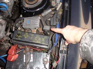
Step 2 - Open the plastic lid and you will see a number of connectors and a description of each on in the lid itself

p1329225_2.jpg


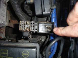
Step 3 - Use a piece of wire/paper clip/something metal to short E1 with either TE1 (MS) or T (MA)

p1329225_3.jpg


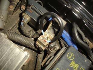
Step 4 - Insert keys and turn them to the 'ON' position - do not start the car! The engine warning lamp will now flash a sequence of error codes at you

p1329225_4.jpg


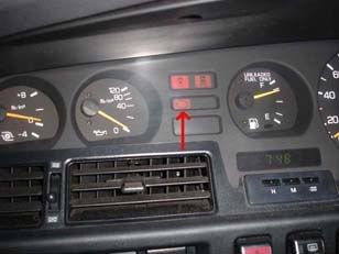
Interpreting the codes:

If you haven't got any stored error codes the light will simply flash on then off at quarter second intervals

If you have any codes they will come out in numerical order (Smallest first). Once the codes are displayed, there will be a pause for 4.5 seconds then it will start again so don't worry if you miss them first time round

Each code will be a two digit number represented by a series of 0.5 second flashes for the numbers and a gap of 1.5 seconds between digits. Between each code is a 2.5 second pause.

An example, code 24 then 31 would be:

Two 0.5 second flashes, a 1.5 second pause, four 0.5 second flashes

Then there would be a 2.5 second pause followed by

Three 0.5 second flashes, a 1.5 second pause, 1 0.5 second flash

Then after 4.5 seconds it starts again
 

JSeaman

SM Official Expert: Guide Author
SM Expert
May 26, 2009
216
0
0
Derbyshire, UK
Note : The ECU should be considered as a potential ‘Area to investigate’ for all codes.

Code 11
=======

Problem Area: ECU
Description: Interrupt to ECU power supply

Areas to investigate:

1. Ignition switch (or circuit)
2. Main relay (or circuit)

---------------------------------------------------------------

Code 6/12
=========

Problem Area: RPM signal
Description: ECU has no “NE” or “G” signal within 2 seconds of cranking

Areas to investigate:

1. Alarm/immobiliser
2. CPS/distributor (or circuits)
3. signal circuit

---------------------------------------------------------------

Code 13
=======

Problem Area: RPM signal
Description: ECU has no “Ne” signal with revs >1000rpm

Areas to investigate:

1. CPS/distributor (or circuits)

---------------------------------------------------------------

Code 3/14
=========

Problem Area: Ignition
Description: ECU has no “IGF” signal

Areas to investigate:

1. Alarm/immobiliser
2. Igniter + coil (or circuits)

---------------------------------------------------------------

Code 5/21
=========

Problem Area: O2 sensor
Description: O2 (lambda) sensor problem in closed loop operation

Areas to investigate:

1. Lambda sensor / circuit

7MGTE ONLY:

Description: 7MGTE: Open or short circuit in heater wiring for sensor

1. Lambda sensor heater / circuit


---------------------------------------------------------------

Code 4/22
=========

Problem Area: Water temp
Description: Open or short circuit in water temp sensor signal

Areas to investigate:

1. Water temp sensor / circuit

---------------------------------------------------------------

Code 8/24
=========

Problem Area: Intake temp
Description: Open or short circuit in intake air temp sensor signal

Areas to investigate:

1. Air temp sensor / circuit
2. AFM, connector and wiring

---------------------------------------------------------------

Code 25
=======

Problem Area: AFR lean
Description: Problem with mixture detected (excessive lean)

Areas to investigate:

1. Fuel injector / circuit
2. Fuel pressure
3. AFM
4. Air intake system
5. O2 sensor / circuit
6. Ignition system
7. Water temp sensor

---------------------------------------------------------------

Code 26
=======

Problem Area: AFR rich
Description: Problem with mixture detected (excessive rich)

Areas to investigate:

1. See above (code 25)
2. Ignition sensor

---------------------------------------------------------------

Code 27
=======

Problem Area: Sub-O2 sensor
Description: California 7MGE: Problem with sub-oxygen signal

Areas to investigate:

1. Sensor / circuit
2. Heater / circuit

---------------------------------------------------------------

Code 28
=======

Problem Area: O2 sensor
Description: See code 21

Areas to investigate:

1. See code 21

---------------------------------------------------------------

Code 2/31
=========

Problem Area: AFM signal
Description:
7MGE: VC open circuit/short circuit between VS and E2 when idle contacts closed
7MGTE: Open or short circuit in AFM signal

Areas to investigate:

1. AFM, connector and wiring

---------------------------------------------------------------

Code 32
=======

Problem Area: AFM signal
Description: 7MGE: Open circuit in E2 or short circuit between VC and VS

Areas to investigate:

1. AFM, connector and wiring

---------------------------------------------------------------

Code 14/34
==========

Problem Area: Turbo pressure
Description: 7MGTE: Turbo pressure abnormal (could be fuel cut, check for boost leaks and bleed valves/shims/boost controller)

Areas to investigate:

1. Turbo
2. AFM
3. Turbo pressure sensor
4. Intercooler

---------------------------------------------------------------

Code 35
=======

Problem Area: HAC signal
Description: 7MGTE: Open or short circuit in HAC circuit

Areas to investigate:

1. Turbo pressure sensor
2. ECU

---------------------------------------------------------------

Code 7/41
=========

Problem Area: TPS signal
Description: Open or short circuit in TPS signal (VTA)

Areas to investigate:

1. TPS sensor / circuit / wiring

---------------------------------------------------------------

Code 9/42
=========

Problem Area: Speed sensor
Description:

1. No “SPD” signal to ECU for 8 seconds between 2500rpm and 400rpm (7MGTE) or 4500rpm (7MGE)
2. Coolant temp < 80&#186;C
3. Neutral start switch is off

Areas to investigate:

1. Speed sensor / circuit
2. On imports, this can be due to improperly delimited vehicles

---------------------------------------------------------------

Code 10/43
==========

Problem Area: Starter signal
Description: ECU has no &#8220;STA&#8221; signal when stationary and <=800rpm

Areas to investigate:

1. Ignition switch / circuit

---------------------------------------------------------------

Code 11/51
==========

Problem Area: Switch state
Description: ECU has no &#8220;IDL&#8221; (TPS), &#8220;NSW&#8221; (Neutral start switch) or &#8220;A/C&#8221; during diagnostics

Areas to investigate:

1. TPS most likely-see code 41
2. A/C switch / circuit
3. A/C amplifier
4. NSW switch circuit

---------------------------------------------------------------

Code 12/52
==========

Problem Area: Knock sensor
Description: Open or short circuit in knock sensor signal

Note: Heat/age can cause the wiring to deteriorate. You can rewire the sensor to the ECU using the old co-axial cable for networks or shielded speaker cable. You do not need to ground the shield

Areas to investigate:

1. Knock sensor / circuit
2. Check connector plugs

---------------------------------------------------------------

Code 13/53
==========

Problem Area: Knock control
Description: Knock control signal fault

Areas to investigate:

1. ECU

---------------------------------------------------------------

Code 71
=======

Problem Area: EGR fault
Description: California: EGR gas temp low during operation or gas temp signal open circuit

Areas to investigate:

1. EGR system, sensors or VSV

---------------------------------------------------------------

Code 72
=======

Problem Area: A/C
Description: Compressor relay/signal fault

Areas to investigate:

1. Compressor/relay circuit