GUIDE : Changing your Lambda sensor
I recommend you get the Lambda sensor and adaptor flange from somewhere like buypartsbuy.co.uk (http://www.buypartsby.co.uk/lambda_sensors.php), and it should cost you about £35 delivered. You want a 3 wire generic sensor.
I'm not going to cover the TSRM procedure for testing the sensor due to the fact it will only show major faults. General wear and tear will have an affect on the sensor and so I decided to change mine as a matter of general maintenance. Once you see the sensor I'm sure you'll agree it is worth doing!
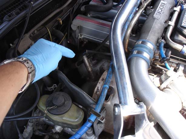
Step 1 - First things first, locate your lambda sensor. This is on the turbo elbow before your cat (if you still have them). Don't worry if your turbo elbow doesn't look identical, mine's aftermarket.
Bit of background: The act of combustion produces a number of gases (hydrocarbons, oxides of nitrogen & carbon etc) and these can tell you a lot about the mixture in the cylinders. A target figure known as stoichiometric is the "chemically correct" ratio at which petrol should be mixed with air for optimal performance against economy & emissions. This figure is about 14.66 to 1 (usually listed asd 14.7:1) and is known as 'Lambda'. Note that there is a trade-off between power & economy (and there are also emissions to consider) and also AFRs can vary significantly depending upon load, throttle (wide open throttle or WOT is a special case for example) and various other factors. For background reading you can look into micro-turbulence (barrow swirls) of lean-burn engines which can happily run AFRs of 22:1.
A lambda sensor sits in the stream of exhaust gases and measures the exhaust's Oxygen content and produces a voltage based on the amount of O2 (Oxygen) present. Why Oxygen? Simple, if there's too much fuel then virtually all the Oxygen gets used up whereas if there is too little fuel there will be an excess of Oxygen in the exhaust gases. The adjustment of the AFR is done in small increments by the ECU to avoid potential problems such as coming off throttle from WOT etc
One thing I can't say for sure is whether the sensor compares the exhaust O2 content with atmospheric or not. I have found numerous references that say this is the case but I'm not 100% certain so if anyone can shed some light that'd be great.
The ECU will have target air-fuel ratios (AFR) for given rev ranges and will use feedback from the lambda sensor to adjust fuelling accordingly. The sensor isn't much use until warm (Usually 350 degrees F to even start functioning and around 600 degrees F before it can react quickly to changes. To aid the warm up, a heating element is incorporated into the sensor. If the sensor is unable to provide valid information, the ECU will use other sensors (knock sensors, afm etc) to control the fuelling but will provide a rich mixture by default. This is fine while the sensor warms up but it does mean poor fuel economoy, reduction in power, and increases in emissions so expect it to show up come MOT time if your sensor starts to fail.
Widebands - A wideband sensor is just another type of O2/Lambda sensor that works across a greater range of AFRs. Stock (narrowband) sensors produce voltage variations around a very small range of AFRs near to the 14.7:1 mark. A wideband works over a much greater range (as much as 10:1 - 25:1)
One final point is that the ECU will only use the Lambda sensor when in 'closed loop' mode. This basically means when it is using the feedback from sensors to tweak the other components (ie fuelling) within the system. In certain circumstances (such as WOT), the ECU will revert to base maps and, as before, run rich.
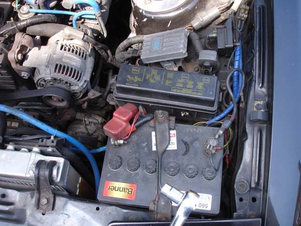
Step 2 - Right, sorry about the essay but on to the guide - Disconnect your battery (10mm nut). This is recommended when you deal with any electrical bits and bobs (not that I usually bother!), but in this case I want the ECU to be reset. I don't know if any of the self-learning performed during a reset is based on the O2 sensor but figure I should give it every chance to improve economy.
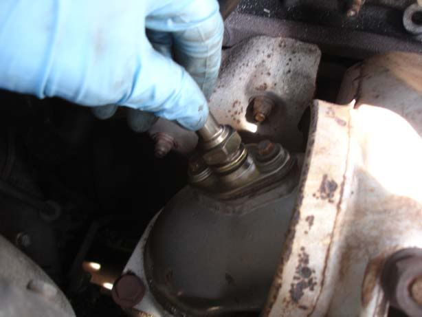
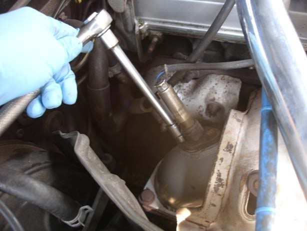
Step 3 - Remove the two 10mm bolts that hold the O2 sensor to the turbo elbow
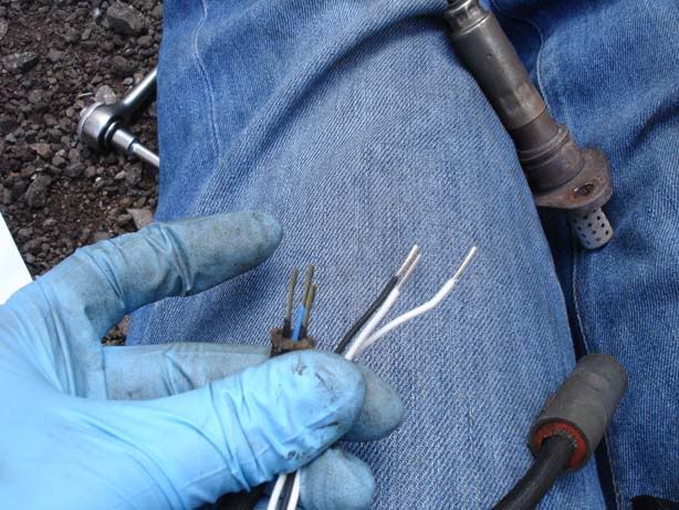
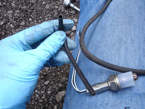
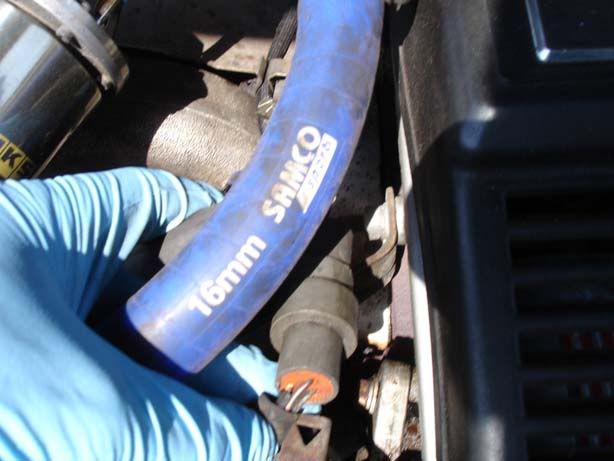
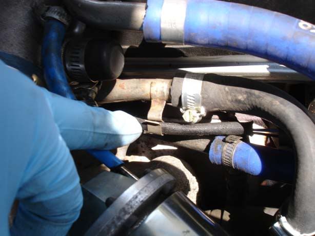
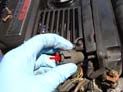
Step 4 - Trace the wiring from the sensor back to the connector (picture 1), and make sure you open the TWO metal clips that hold the wire in position (picture 2 shows 1 of them). Disconnect the sensor wiring - the third picture shows the connector and I've highlighted the tab you need to pull upwards to free it from the sensor-end of the connector.
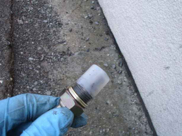
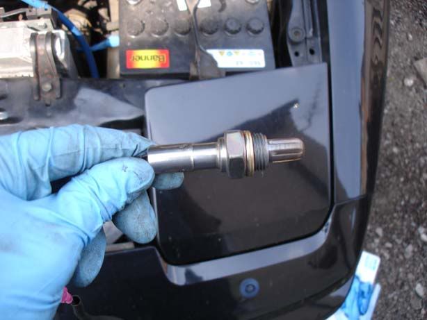
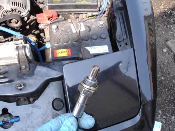
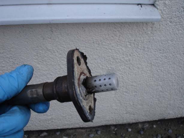
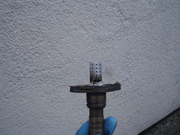
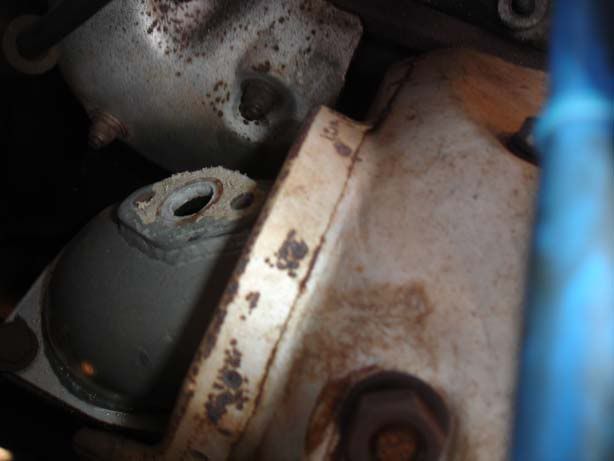
Step 5 - You should now be able to remove the sensor from the car and examine it. I've attached a couple of pictures of the state mine was in and one of the turbo elbow gasket surface.
From a bit of reading around, it seems you can get a white build up like this from a silicone gasket and my gasket surface was white and powdery so I assume this may be the case. Oxidised silicone poisons the pores of the sensor by preventing larger molecules from passing (e.g. O2) whereas smaller molecules do (such as Hydrogen) so be sure you get an "Oxygen sensor safe" gasket material such as the one I used.
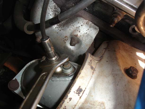
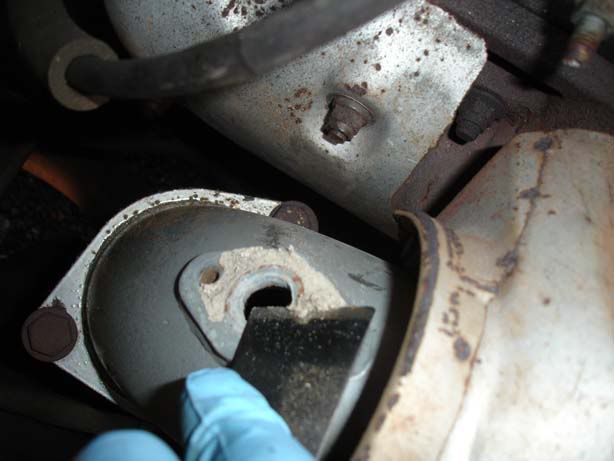
Step 6 - Clean up the surface of the turbo elbow where the gasket will sit to seal the sensor in place. I used a wallpaper scraper for this and gently removed the build up of white powder. Try and avoid getting it in the exhaust (stuff a rag in the O2 sensor hole if you like), especially if you've still got cats.
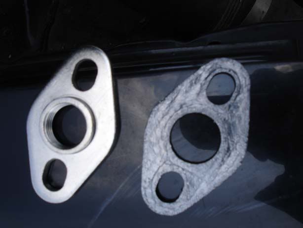
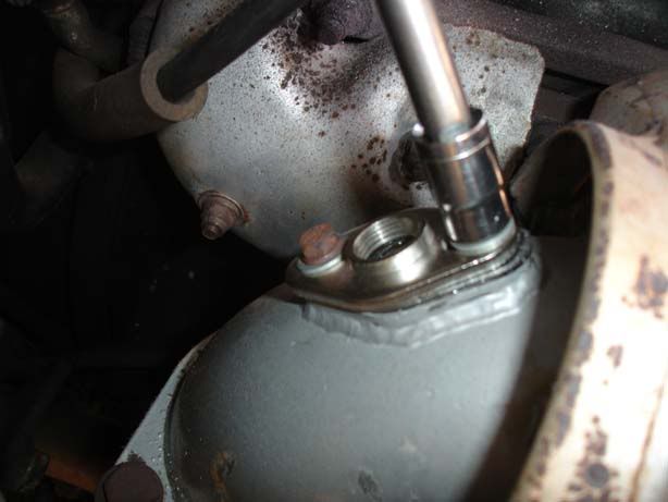
Step 7 - The Supra use a mounting flange rather than a screw-fit connection for the Lambda sensor so need to convert it. Keep this in mind if you buy a generic sensor because you will probably need to buy an adaptor to fit the flange-style lamba sensors. You should have a gasket and flange as shown in the first picture. If the gasket has a smooth surface and one with ridges then have the smooth surface against the turbo elbow. Fit the gasket and flange to the turbo elbow (second picture)
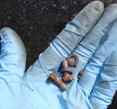
NOTE : Both my 10mm bolts that I removed were threaded (see third picture), in case you find the same but have new bolts on standby. Also, the holes in the adaptor flange were too big for stock bolts so you'll need to replace them or get a washer to cater for this. I haven't got a stock turbo elbow so can't give you the proper bolts sizes but in my case there only a shallow recess for the bolts so don't get long ones.
I recommend you get the Lambda sensor and adaptor flange from somewhere like buypartsbuy.co.uk (http://www.buypartsby.co.uk/lambda_sensors.php), and it should cost you about £35 delivered. You want a 3 wire generic sensor.
I'm not going to cover the TSRM procedure for testing the sensor due to the fact it will only show major faults. General wear and tear will have an affect on the sensor and so I decided to change mine as a matter of general maintenance. Once you see the sensor I'm sure you'll agree it is worth doing!
Step 1 - First things first, locate your lambda sensor. This is on the turbo elbow before your cat (if you still have them). Don't worry if your turbo elbow doesn't look identical, mine's aftermarket.
Bit of background: The act of combustion produces a number of gases (hydrocarbons, oxides of nitrogen & carbon etc) and these can tell you a lot about the mixture in the cylinders. A target figure known as stoichiometric is the "chemically correct" ratio at which petrol should be mixed with air for optimal performance against economy & emissions. This figure is about 14.66 to 1 (usually listed asd 14.7:1) and is known as 'Lambda'. Note that there is a trade-off between power & economy (and there are also emissions to consider) and also AFRs can vary significantly depending upon load, throttle (wide open throttle or WOT is a special case for example) and various other factors. For background reading you can look into micro-turbulence (barrow swirls) of lean-burn engines which can happily run AFRs of 22:1.
A lambda sensor sits in the stream of exhaust gases and measures the exhaust's Oxygen content and produces a voltage based on the amount of O2 (Oxygen) present. Why Oxygen? Simple, if there's too much fuel then virtually all the Oxygen gets used up whereas if there is too little fuel there will be an excess of Oxygen in the exhaust gases. The adjustment of the AFR is done in small increments by the ECU to avoid potential problems such as coming off throttle from WOT etc
One thing I can't say for sure is whether the sensor compares the exhaust O2 content with atmospheric or not. I have found numerous references that say this is the case but I'm not 100% certain so if anyone can shed some light that'd be great.
The ECU will have target air-fuel ratios (AFR) for given rev ranges and will use feedback from the lambda sensor to adjust fuelling accordingly. The sensor isn't much use until warm (Usually 350 degrees F to even start functioning and around 600 degrees F before it can react quickly to changes. To aid the warm up, a heating element is incorporated into the sensor. If the sensor is unable to provide valid information, the ECU will use other sensors (knock sensors, afm etc) to control the fuelling but will provide a rich mixture by default. This is fine while the sensor warms up but it does mean poor fuel economoy, reduction in power, and increases in emissions so expect it to show up come MOT time if your sensor starts to fail.
Widebands - A wideband sensor is just another type of O2/Lambda sensor that works across a greater range of AFRs. Stock (narrowband) sensors produce voltage variations around a very small range of AFRs near to the 14.7:1 mark. A wideband works over a much greater range (as much as 10:1 - 25:1)
One final point is that the ECU will only use the Lambda sensor when in 'closed loop' mode. This basically means when it is using the feedback from sensors to tweak the other components (ie fuelling) within the system. In certain circumstances (such as WOT), the ECU will revert to base maps and, as before, run rich.
Step 2 - Right, sorry about the essay but on to the guide - Disconnect your battery (10mm nut). This is recommended when you deal with any electrical bits and bobs (not that I usually bother!), but in this case I want the ECU to be reset. I don't know if any of the self-learning performed during a reset is based on the O2 sensor but figure I should give it every chance to improve economy.
Step 3 - Remove the two 10mm bolts that hold the O2 sensor to the turbo elbow
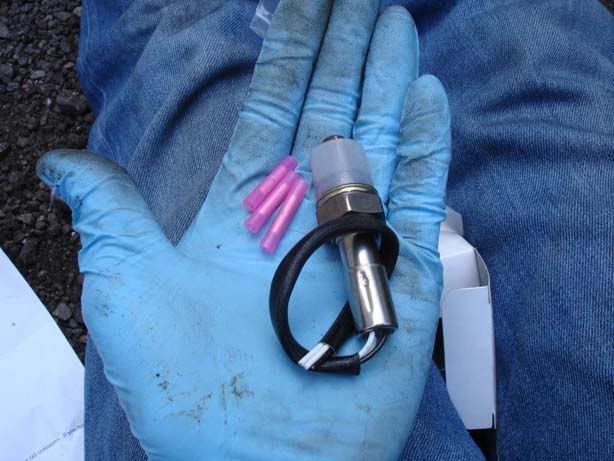
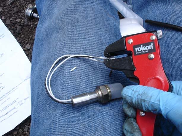
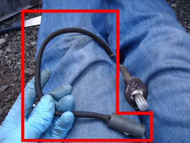
Step 4 - Trace the wiring from the sensor back to the connector (picture 1), and make sure you open the TWO metal clips that hold the wire in position (picture 2 shows 1 of them). Disconnect the sensor wiring - the third picture shows the connector and I've highlighted the tab you need to pull upwards to free it from the sensor-end of the connector.
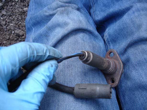
Step 5 - You should now be able to remove the sensor from the car and examine it. I've attached a couple of pictures of the state mine was in and one of the turbo elbow gasket surface.
From a bit of reading around, it seems you can get a white build up like this from a silicone gasket and my gasket surface was white and powdery so I assume this may be the case. Oxidised silicone poisons the pores of the sensor by preventing larger molecules from passing (e.g. O2) whereas smaller molecules do (such as Hydrogen) so be sure you get an "Oxygen sensor safe" gasket material such as the one I used.
Step 6 - Clean up the surface of the turbo elbow where the gasket will sit to seal the sensor in place. I used a wallpaper scraper for this and gently removed the build up of white powder. Try and avoid getting it in the exhaust (stuff a rag in the O2 sensor hole if you like), especially if you've still got cats.
Step 7 - The Supra use a mounting flange rather than a screw-fit connection for the Lambda sensor so need to convert it. Keep this in mind if you buy a generic sensor because you will probably need to buy an adaptor to fit the flange-style lamba sensors. You should have a gasket and flange as shown in the first picture. If the gasket has a smooth surface and one with ridges then have the smooth surface against the turbo elbow. Fit the gasket and flange to the turbo elbow (second picture)
NOTE : Both my 10mm bolts that I removed were threaded (see third picture), in case you find the same but have new bolts on standby. Also, the holes in the adaptor flange were too big for stock bolts so you'll need to replace them or get a washer to cater for this. I haven't got a stock turbo elbow so can't give you the proper bolts sizes but in my case there only a shallow recess for the bolts so don't get long ones.