EFI main relay and the Fuel Pump Computer in the event of an Crash - JDM 1JZ

Radial

New Member
Aug 20, 2011
252
0
0
Norway
Hi there

According to theese wiring-diagrams, the EFI relay is the main powersource for the JDM Soarer 1JZ-GTE fuel pump circiut, as its the only supplier for +12v to the fuel pump computer:

http://wilbo666.pbworks.com/w/file/fetch/51111357/xZZ3x%20Electrical%20Wiring%20Diagram%206737105%203-6.png
http://wilbo666.pbworks.com/w/file/fetch/51111360/xZZ3x%20Electrical%20Wiring%20Diagram%206737105%203-7.png

Pinout explanations:
http://wilbo666.pbworks.com/w/page/47216384/1JZ-GTE%20JZZ30%20Soarer#JZZ30ToyotaSoarer1JZGTEWiringDiagrams

With theese diagrams, I figured out that the terminals on the Fuel Computer are:

E: Earth for Computer (Same as Pump)
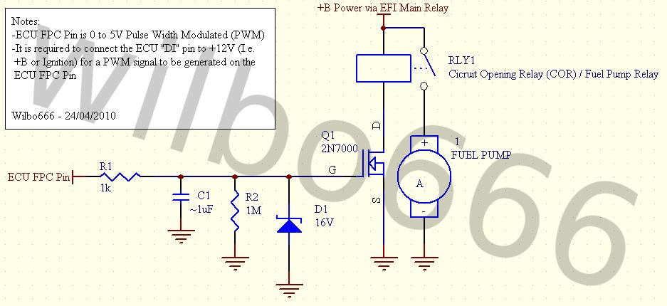
FP: 9 or 12v powersupply to pump (depending on FRC signal)
DI: Diagnostic input to the ECU, if the Fuel Computer is not healthy (Normaly 12v supplied from FC, if missing 12v FC is bad)
FRC: Puls Modulated signal from ECU, setting the 9 or 12v to the Fuel Pump.
B: Battery +12v supply.


I have shorted the B and the FP plug.... to make shure my external fuel pump relay is supplied with 12v instead of 9v, as the relay started to make strange clicking-noises (typical for 9v supply) at idle. But will the EFI main relay switch off in the event of a crash? (if the engine stops, etc)
As far as I can see, the Main relay is controlled by the ECU itself, and the ECU must have some sort of safety-function with this relay? What else will stop the Fuelpump in the event of a crash.... the Pulse Modulated signal?


Just need some information, as this is a race-car and they crash alot ;)

Thanx
 

bioskyline

New Member
Oct 21, 2010
1,236
0
0
powell river bc
i dug some info on this, mostly from a refernce for swaping efi systems into carberated vehicals.

on some ecus, they use the oil pressure sensor as a "engine on" monitor. aslong as there is oil pressure it will keep the fuel flowing. if the ecu reads no oil pressure, it shuts off. not sure if the jz one does, but you can buy ones that do, links below

http://www.summitracing.com/parts/HLY-12-810/
http://www.summitracing.com/parts/CRT-A68301/

alternately if you want to be real safe, ford uses an inertia Switch that is wired in-line with the fuel pump relay coil. If the inertia switch receives a harsh enough physical jolt - as happens in an accident - then a small spring-loaded set of contacts opens and cuts power to the fuel pump relay. There is a small button on the inertia switch to allow it to be "reset" in case of a false triggering (such as an overly enthusiastic door, trunk, or hatch slamming) or real triggering (such as a fender-bender or other accident). You will find these in the trunk of most 90+ ford cars on the passenger side, and shouldn't cost to much at any junkyard for one.

pics
2007-10-24_162330_Ford_inertia_switch.jpg

p1844307_1.jpg
 

destrux

Active Member
May 19, 2010
1,183
10
38
PA
The EFI main relay will not shut the fuel pump off if the engine stalls in a crash. It only shuts the pump off if you shut the key off. An easy test to check this is to stall the car out with the clutch and listen for the pump.

The switch IJ is talking about is probably the best way.

I would avoid an inertia switch or an oil pump switch.

The reason I say that is because they both cut the fuel pump, and can be false triggered.

The oil pressure switch is liable to cut fuel pressure during a long high speed turn when the oil sloshes and the pump draws in air. Momentary oil starvation is bad enough, without adding detonation to the mix at the same moment.

The inertia switch might be set off by rough roads or during a minor impact (like a short trip through the gravel traps or a bounce off the curbing). I've never used one in any of my cars though, so I could be wrong about them being too sensitive. I know for sure that I'd wire one of these to cut the main relay though, and not just the pump. If it's false triggered and cuts just the pump that would be bad. I'd also mount it very close to the driver, or mount a bypass switch near the driver to get the car moving quickly if it pops and leaves you sitting in a bad spot.

I need to implement something on my car, I never thought about the pump running with a ruptured fuel line after an accident. Chances are I'd be able to shut the motor off, which would kill the pump, but you never know.
 

destrux

Active Member
May 19, 2010
1,183
10
38
PA
Satan;1844341 said:
I thought that the 12v mod addressed the FP Relay and kept the stock fuel cut off feature in place... I am getting ready to do the 12v mod in the next few weeks, with the intent of keeping the cut off feature.

http://www.supramania.com/forums/showthread.php?78225-Fuel-pump-upgrade-amp-wiring-12v

Anyone?

It does if you're doing it with a car that never had a fuel pump ECU. If you have a 2JZ swap or one of the 1JZ engines that use a fuel pump ECU in the donor car (soarer, chaser) the ECU cuts the pump by cutting the PWM signal to the pump ECU, and the pump ECU cuts the pump. When you swap one of these into a MKIII you have to wire the fuel pump relay to turn on with the ECU since those ECUs have no fuel pump control wire (none that the relay can use anyway). On the cars that just have a pump speed control relay (like the 7MGTE) eliminating the speed control relay won't remove the pump safety shutoff. The ECU will still shut the other fuel pump relay off. I'm not sure how the 1JZ supras are set up from the factory.
 

Satan

Supramania Contributor
Mar 31, 2005
1,594
0
36
Tampa
I was just helping a friend over the weekend w/their 1JZ swap and was told to use the FC (Fuel Cut-off) signal from the ECU, in place of the FC signal from the 7M ECU... I believe it monitors a couple of other signals to know when to cut off the fuel pump (STA and another one).

I am using a 2JZ in mine and do not have that signal, which is why I was looking at the 12v mod (maybe option 2 or 3) to achieve the same result. I currently have the B1 #6 wire grounded, so that the fuel pump comes on when the key is in the on position, but there is not any fuel cutoff (AFAIK).
 

ifyouaint1sturlast

Banned Scammer - I'm whitemike.
Jun 14, 2011
480
0
0
Fort Myers/Cape Coral - Florida
^ I am going to experiment with this soon.

Pin 22 of the 40-pin connector would need to be fed 12v to 'trick' the ECU into thinking you had the 2JZ fuel pump ECU connected. Easy enough.

Pin 23 of the 40-pin connector will then output 0v-5v 'to the fuel pump ECU' depending on how hard it wants the fuel pump to work.

As long as the output is greater than 0v can it keep a relay open? Then accident, then ECU says no more fuel, 0v .. relay pops. No more fuel?
 

Radial

New Member
Aug 20, 2011
252
0
0
Norway
This was a good thread, finally gathering some information :) So, if information is correct, it turns out that the Fuel Pump Computer is controlled by the PWM signal from the ECU.

When the PWM signal goes to Zero pulses, the FPC stops the pump.

So I did some research about PWM control of electronic Circuits.... and the result was quite interesting.
A PWM circuit is almost the same as a Relay-circuit, but it uses the "relay function" within the FPC to quickly pulse the power to the pump, at the rate of the PWM signal.

The PWM signal then probably has 3 frequencies... since every one tells they measure 0, about 7 and finally 12V at the pump,depending om RPM and TPS position.
Higher frequency in the PWM signal, makes the relay work faster, and a greater nominal pump voltage is achieved, increasing the pump speed.

If we manage to find the Voltage of the PWM signal, and the 7v pump frequency, its just to insert a Capacitor on the PWM signal line...... the PWM signal wil now be "Constant" (no frequency), and the FPC should now close its relay function completely, giving you the Full 12V output at ALL times.
When engine is shut off, the ecu PWM signal goes to Zero... the capacitor discharges (within, say half a second), and the FPC shuts down the Fuel Pump.


A very complicated way of doing it, but it will then remain almost Stock.... but it requires some equipment and calculation. I will give you a heads up on the upcomming solution.

The EASIEST way is to find this Propane relay mentioned above, that is connected to the Ignitor/Coil (Or RPM output for Tacho on the ECU??) . But I cant seem to find any of those...
 

Satan

Supramania Contributor
Mar 31, 2005
1,594
0
36
Tampa
ifyouaint1sturlast;1845002 said:
^ I am going to experiment with this soon.

Pin 22 of the 40-pin connector would need to be fed 12v to 'trick' the ECU into thinking you had the 2JZ fuel pump ECU connected. Easy enough.

Pin 23 of the 40-pin connector will then output 0v-5v 'to the fuel pump ECU' depending on how hard it wants the fuel pump to work.

As long as the output is greater than 0v can it keep a relay open? Then accident, then ECU says no more fuel, 0v .. relay pops. No more fuel?

Sounds interesting... Though on my ECU #22 is the Fuel pump ECU and #23 is the ACMG (A/C Magnetic Clutch signal). I dunno that the ACMG is a good signal to use, 'cause I thought it controls the AC signal (so that it shuts off at WOT, etc).
 

Satan

Supramania Contributor
Mar 31, 2005
1,594
0
36
Tampa
Ordered parts needed for 12v mod, but did not find much on the propane relay. Still very interested in a bit more safety... any new ideas/updates?
 

Radial

New Member
Aug 20, 2011
252
0
0
Norway
ifyouaint1sturlast;1847585 said:

HAH!!! Thats the schematic solution!!


Allthough, I have found another way of solving the problem that is much easier... will post a drawing very soon.
 

Radial

New Member
Aug 20, 2011
252
0
0
Norway
This is what i'm doing at the moment....

As the stock FP ECU only goes as low as 7v, we just need a relay that can keep closed even at low voltage.
Solution is This Semiconductor-relay! :) It handles 4V up to 32V, uses just 20mA to keep closed, AND can handle up to 25A of current. Spec sheet in link (its a norwegian electronics shop, but information is in english)

https://www1.elfa.se/data1/wwwroot/assets/datasheets/AQA_eng_datasheet.pdf

I have added a quite big Capacitor to the "coil side" of the relay (even though, its not a coil inside the Semiconductor-relay, its based on Transistors) to "smoothen" out any ripples from the FP ECU...... this capacitor can probably be ALOT smaller.... and I have a few Caps in the 50microF range laying around.... so I will probably use that one instead of a 500 one.

Remember, 1000microF is 1F.....1F is the size for a decent 1000W Car audio system- Capacitor.... Correct me if im wrong.


Fuel Pump Solution.jpg
 

Radial

New Member
Aug 20, 2011
252
0
0
Norway
HAHA! It works Perfectly!!!!!! The fuelpump starts as the engine turns, and the pump stops 3 sec. after engine has stopped! Just as stock, but now with a Much bigger fuelpump installed.

The SSR (Solid State Relay) i ordered the first time was incorrect, as it was intended for AC power and not DC and it did not switch off the pump.

So I bought this relay on ebay instead:
http://www.ebay.com/itm/25067201151...NX:IT&_trksid=p3984.m1497.l2649#ht_1873wt_902

Joined a 15 microfarrad capacitor on the coil side for a more stable voltage to the SSR (not realy necessary, it works without it).

She fired up like a dream.

There is a 0,5V voltage-loss over the SSR relay-output, but thats the backside of using an SSR... Voltageloss means something is using some power from the circiut, and that generates some heat. Thats why the heatsink is there. It never gets hot... with 15A of current through the relay, it gets 25c (celcius) and stabilizes there during operation.
 

Radial

New Member
Aug 20, 2011
252
0
0
Norway
New information;
Been testing this setup for a few "full load" race conditions now, and that heatsink gets boiling hot. Will install a 80x80mm or 60x60mm 12v computer cooling-fan on the heatsink to remove more heat from the relay. ill give you some more feedback after testing.
 

Radial

New Member
Aug 20, 2011
252
0
0
Norway
Fan solved the heat-problem totally.... Computer fans works like a charm. Just go with whatever size you want, but a 50x50mm would prabably fit best on my SSR heatsink.
I had to use a 100x100mm fan because that was the smalles fan the shop had in stock at that time, and a drift-event was just around the corner.

SSR + Heatsink + 12v fan for computers = Success

Fan's +12V is wired to the SSR output and grounded, so it starts when the SSR engages (Cause that's when it needs cooling, really)


However, i'm going for Megasquirt 3 this winter season and will go back to a simple "12v relay" solution since the MS3 has the simple "on/off" fuel-pump output.
 
Last edited: