INSTALLATION INSTRUCTIONS FOR SUPRA MKIII 13 INCH WILWOOD FRONT BRAKE KIT.
When you receive your kit open it to inspect the contents of the kit. In the inside the main box you should find two boxes, inside the top box you should have 3 Wilwood boxes, 2 Caliper boxes and 1 Brake Pad box. Each caliper box contains a complete set of left components or right components. The left caliper bracket is packaged with the left caliper. The right caliper bracket is packaged with the right caliper.
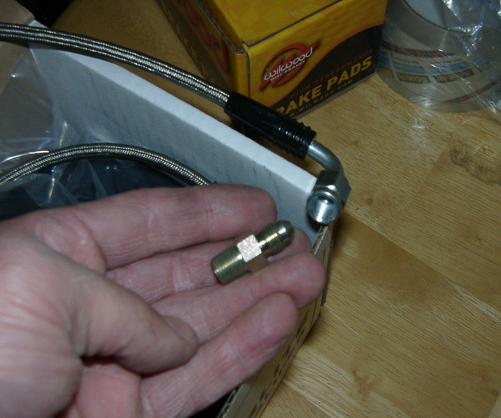
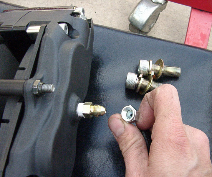
Inside each Caliper box should be a Caliper, a Brake line, and a Caliper bracket.
Attached to each Brake line should be the Brake line Adapter, and a Brake line Clamp.
Attached to each Caliper Adapter Bracket should be all the required fasteners to attach the caliper bracket to the Spindle/Up-right
and all the fasteners to attach the calipers to the bracket.
All of the fasteners installed on the caliper bracket are installed in the sequence they will be installed on the vehicle. DO NOT
remove them until you are ready to install them on the vehicle.
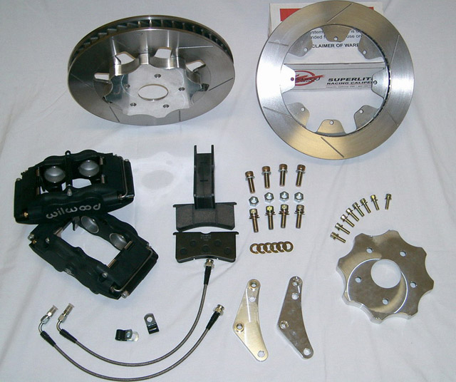
Here are all the parts for the complete front 13 inch Wilwood front brake kit. 01
The first order of business is to remove the front wheels. If you need any assistance on where to lift from or where to place the
jack stands refer to the TSRM. If you were ever going to clean detail the fenderwell this would be the time to do it. If you plan
to detail the fenderwell area after the kit is installed I would recommend removing the caliper from the spindle and placing it in a garbage/big ziplock bag and zip tieing it out of the way (so as not to scratch it). Also remove the rotor and set aside. Do not use Castrol Superclean in the purple bottle, it has a chemical that attacks aluminum. Also don’t use Eagle 1 mag cleaner made for open pore aluminum (like
Centerline wheels).
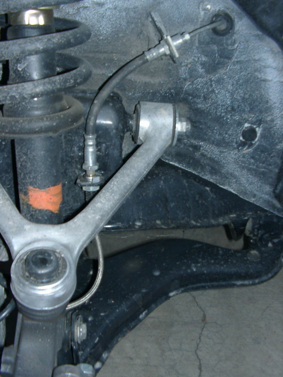
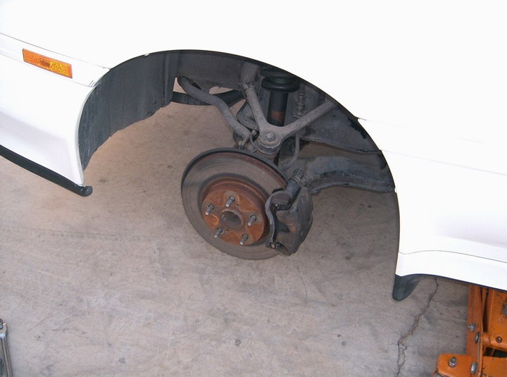
Once you have removed the wheels and supported the vehicle properly it should look like this. 02
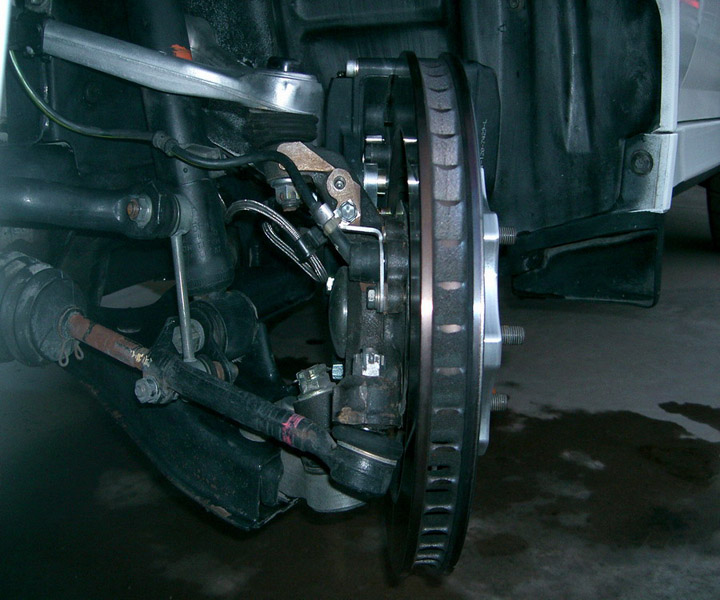
Remove the brake from the spindle and let it hang from the brake line. You won’t break the brake line apart until you have almost
all of the parts installed on each corner you are replacing. 03
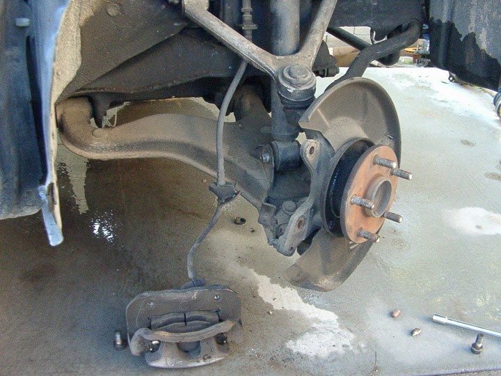
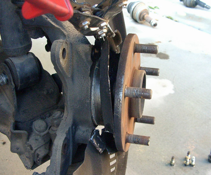
Remove the front rotor hat from the spindle, notice the 2 threaded holes on the stock rotor hat these are used to help remove the
rotor from the hub. Refer to the TSRM if your not familiar with this procedure.
DO NOT POUND OR STRIKE THE WHEEL MOUNTING SURFACE EVER.
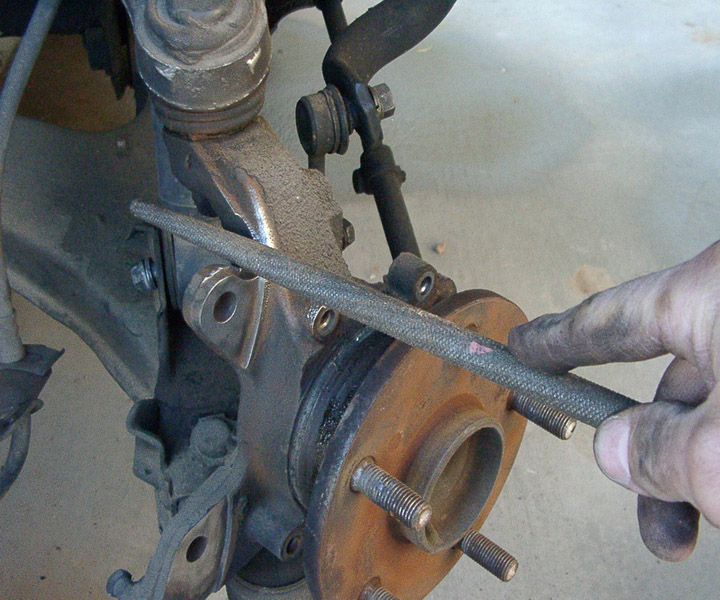
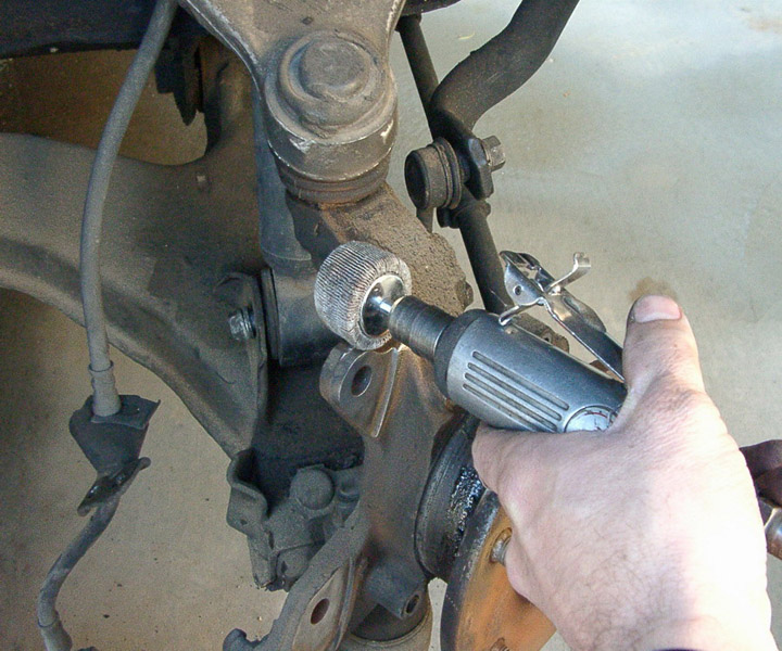
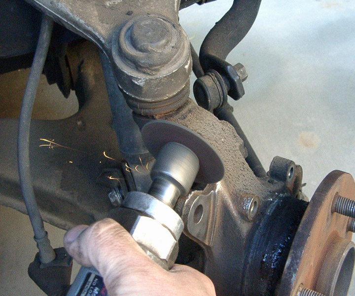
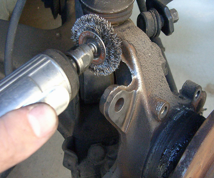
Once the rotor and caliper have been removed you have some cleaning to do. Use a wire brush or any means possible to remove any rust or scale from the surface that the new rotor hat will mount to. This cleaning is Critical to a true running rotor.
I use a wire brush on a die grinder. MAKE SURE TO USE SAFETY GLASSES A FACE SHIELD AND LEATHER GLOVES. My bare hand is only holding the
tool for photographic purposes. If you don’t have experience using these tools get someone that does, or pay a professional to
install these brakes. 04
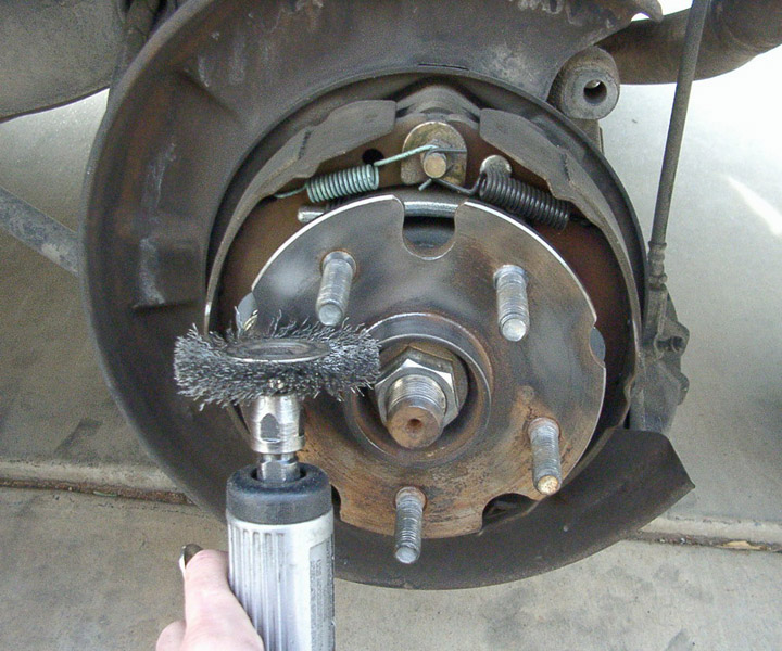
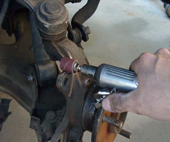
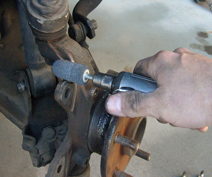
Leaving the lug nuts installed is a good way to insure you don’t damage the threads during this operation.
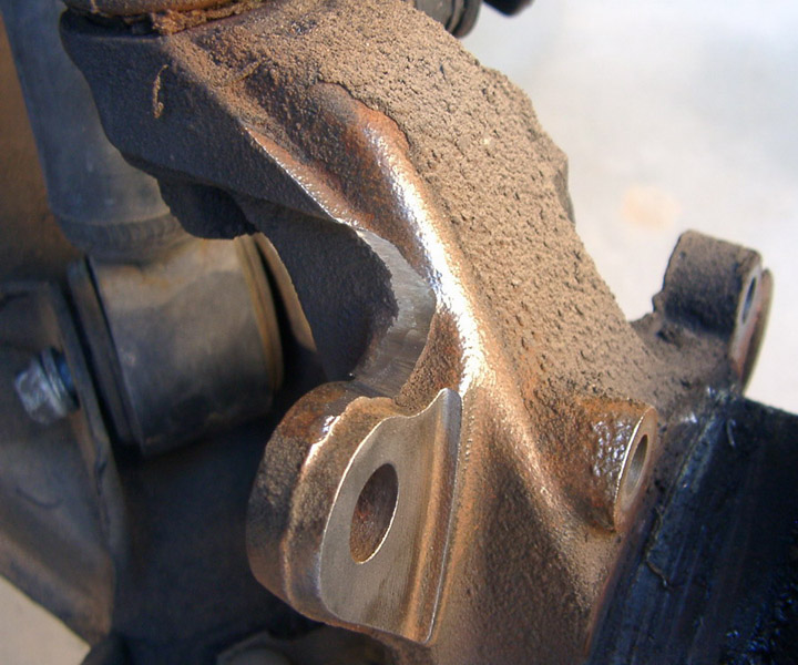
After the mounting surface and the outside diameter of hub mounting surface is clean it should look like this. 05
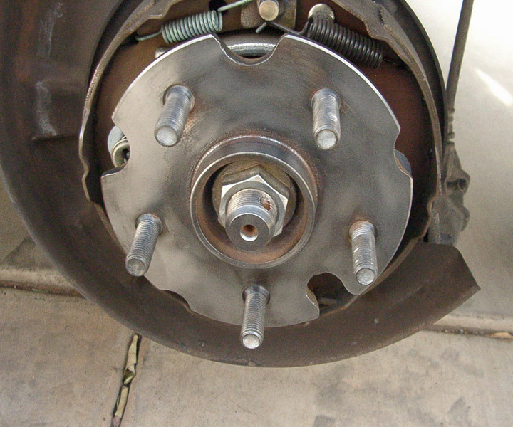
Remember the rotor hat is hubcentric cleaning that hub/center outside diameter is critical to runout.
THIS STEP IS OPTIONAL, YOU CAN SKIP THIS STEP IF YOU DO NOT WISH TO REMOVE THE DUST COVER ON AN ABS VEHICLE!!!
Next you will remove the rotor dust cover. There are several ways to do this I will cover a few of them
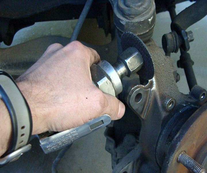
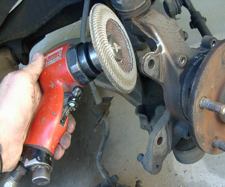
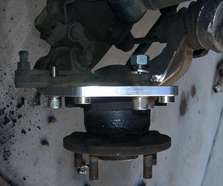
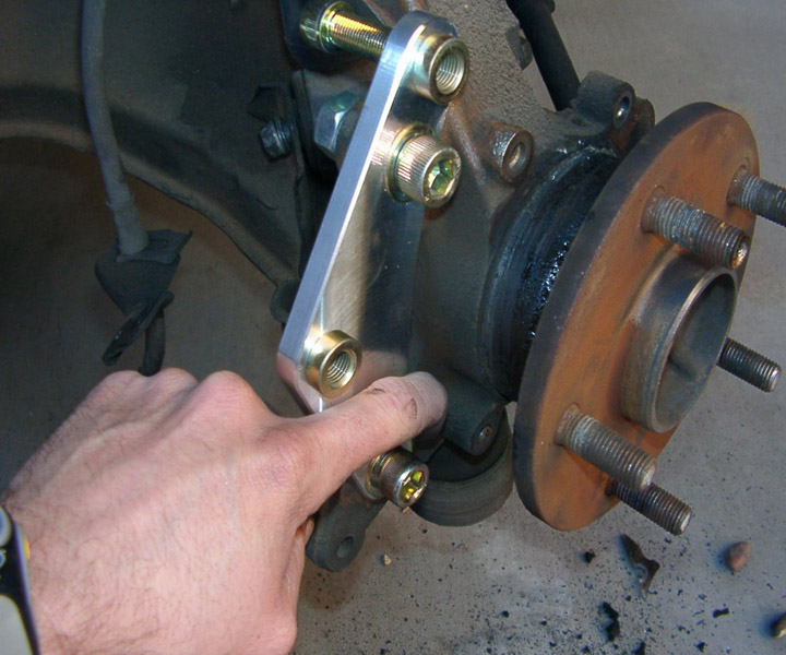
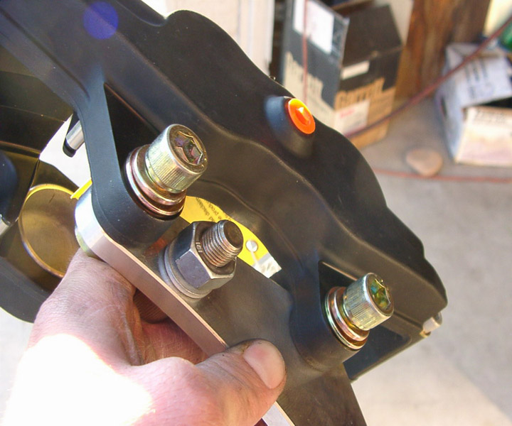
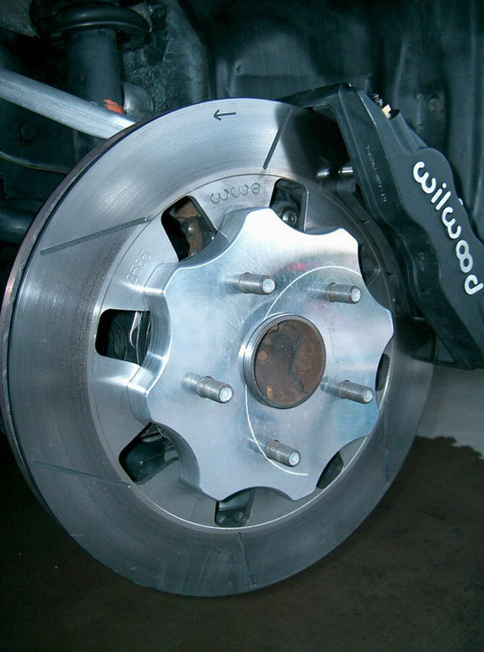
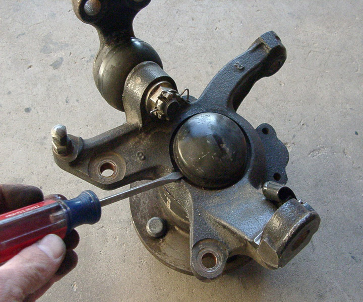
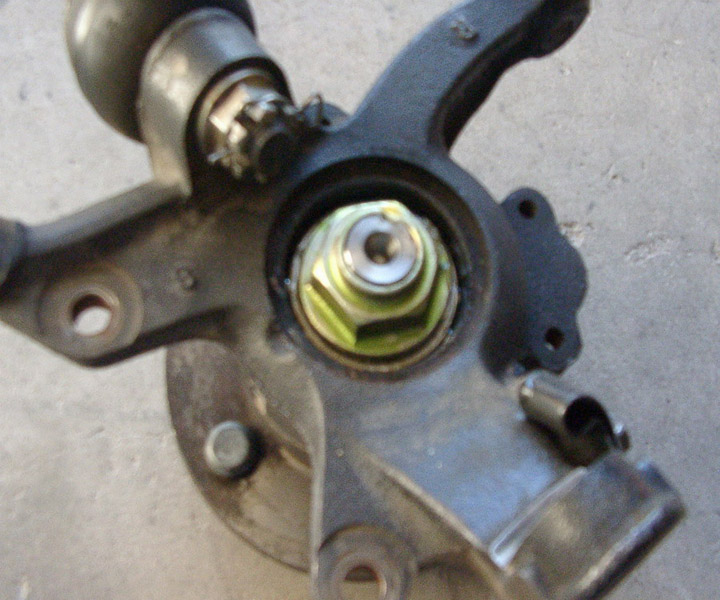
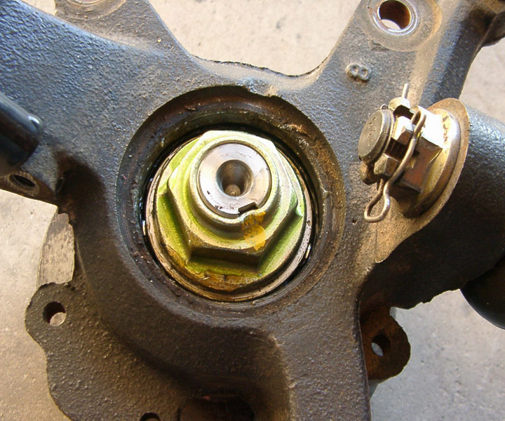
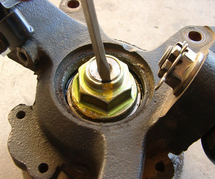
The most difficult and potentially damaging (to the wheel bearings) is to remove the nut for the hub on the back (in board) side of
the spindle. This is the riskiest option, you risk getting dirt in the bearings, you risk damaging the threads, and you risk over
or under torqueing the bearings. It is an option but I do not recommend it. 06, 07, 08, 09
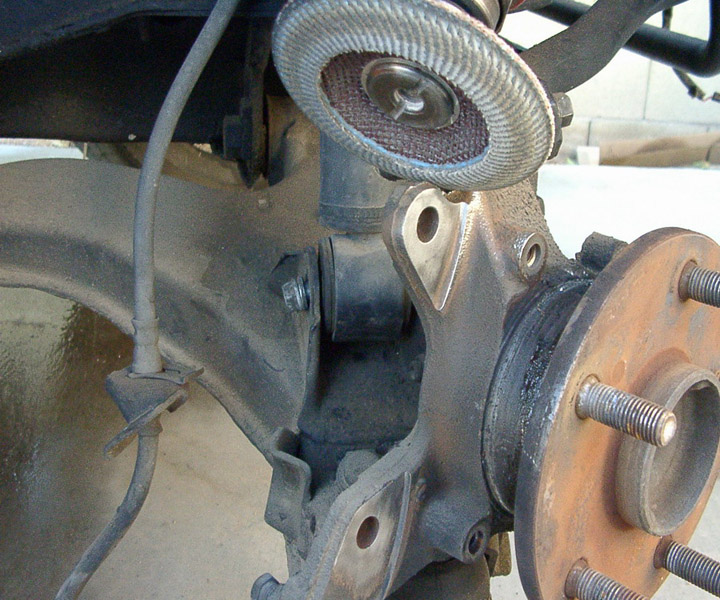
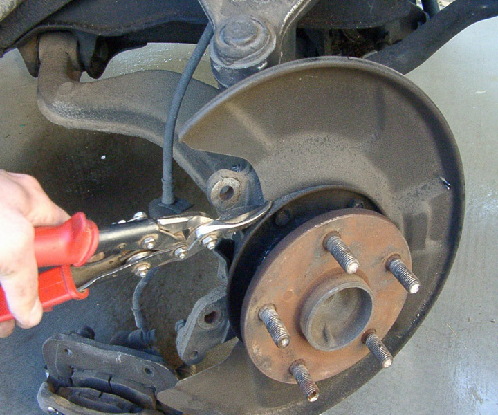
The options I DO recommend will depend on if you have ABS or not. If you have ABS I recommend trimming only the outer dust shield
off of the dust cover assembly ( I say assembly because it is multiple pieces welded together). You can use common aviation tin
snips. Make sure to finish the edges with a file to remove any sharp edges and burrs (prime and paint as necessary). The photo
below shows a non ABS spindle. Notice you can see the fasteners holding the dust cover to the spindle. On an ABS vehicle, the ABS
trigger ring obscures these fasteners and any attempt to gain access to these fasteners using tin/aviation snips risks damaging
that trigger ring. 10, 101
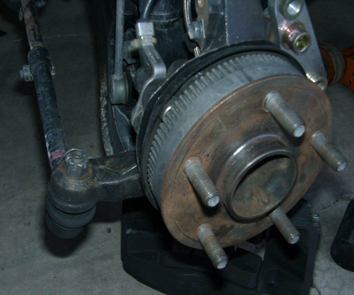
Here is an ABS spindle after removal of the dust cover. You can trim it right down to the outside diameter of the inside flange.
On a non ABS vehicle I recommend loosening these fasteners and trimming a portion of the center out so that the complete dust cover
can be removed. This will avoid tampering with a perfectly good wheel bearing assembly.
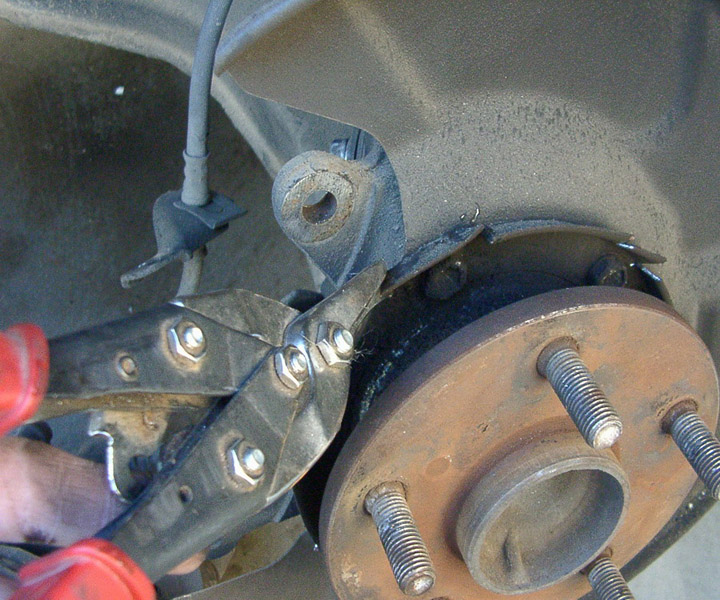
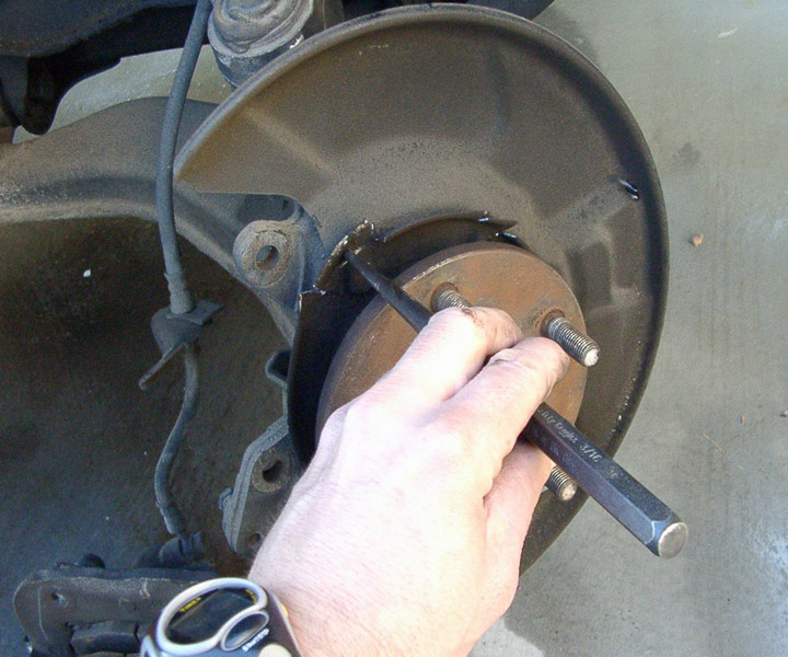
In the first photos I snip the inner ring on each side of the fasteners (to provide clearance for the wrench to gain access to the
head of the bolts). Next I use a drift or punch to knock back the inner ring of the dust cover (in front of the fasteners only).
11, 12
Next I loosen and remove the fasteners holding the dust cover on. Once the dust cover is free I use the snips once again to make a
big opening in the center diameter to slide the dust cover off of the spindle.13,14,
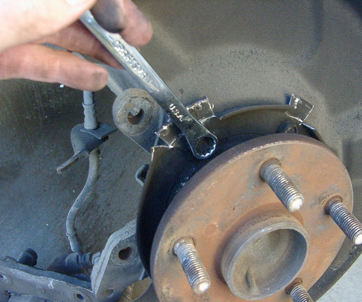
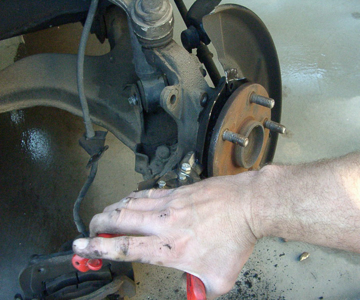
I snip high and low, and the cover comes right off. 15,16,
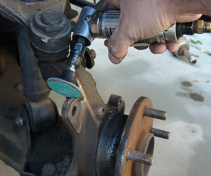
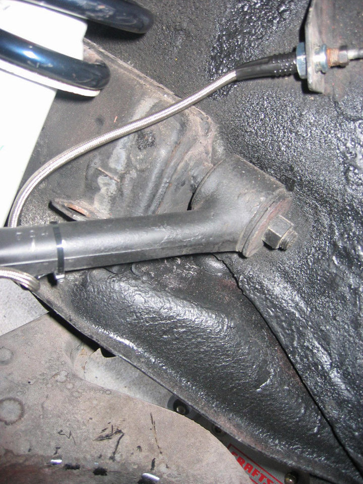
Next you will need to clean and wire brush the mounting surfaces of the Toyota caliper ears. 17,18
I recommend cleaning the whole spindle but if your pressed for time at least make sure you clean these 3 areas. Again if your not
familiar or not comfortable using these tools please have a professional perform this installation. This portion of the casting
interferes slightly with the installation of your new brake caliper. You will need to clearance this portion of the casting. 19,
When you receive your kit open it to inspect the contents of the kit. In the inside the main box you should find two boxes, inside the top box you should have 3 Wilwood boxes, 2 Caliper boxes and 1 Brake Pad box. Each caliper box contains a complete set of left components or right components. The left caliper bracket is packaged with the left caliper. The right caliper bracket is packaged with the right caliper.
Inside each Caliper box should be a Caliper, a Brake line, and a Caliper bracket.
Attached to each Brake line should be the Brake line Adapter, and a Brake line Clamp.
Attached to each Caliper Adapter Bracket should be all the required fasteners to attach the caliper bracket to the Spindle/Up-right
and all the fasteners to attach the calipers to the bracket.
All of the fasteners installed on the caliper bracket are installed in the sequence they will be installed on the vehicle. DO NOT
remove them until you are ready to install them on the vehicle.
Here are all the parts for the complete front 13 inch Wilwood front brake kit. 01
The first order of business is to remove the front wheels. If you need any assistance on where to lift from or where to place the
jack stands refer to the TSRM. If you were ever going to clean detail the fenderwell this would be the time to do it. If you plan
to detail the fenderwell area after the kit is installed I would recommend removing the caliper from the spindle and placing it in a garbage/big ziplock bag and zip tieing it out of the way (so as not to scratch it). Also remove the rotor and set aside. Do not use Castrol Superclean in the purple bottle, it has a chemical that attacks aluminum. Also don’t use Eagle 1 mag cleaner made for open pore aluminum (like
Centerline wheels).
Once you have removed the wheels and supported the vehicle properly it should look like this. 02
Remove the brake from the spindle and let it hang from the brake line. You won’t break the brake line apart until you have almost
all of the parts installed on each corner you are replacing. 03
Remove the front rotor hat from the spindle, notice the 2 threaded holes on the stock rotor hat these are used to help remove the
rotor from the hub. Refer to the TSRM if your not familiar with this procedure.
DO NOT POUND OR STRIKE THE WHEEL MOUNTING SURFACE EVER.
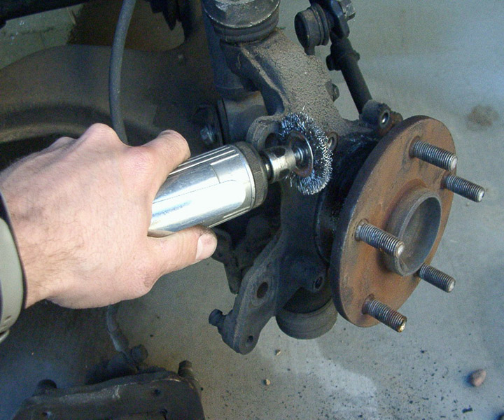
Once the rotor and caliper have been removed you have some cleaning to do. Use a wire brush or any means possible to remove any rust or scale from the surface that the new rotor hat will mount to. This cleaning is Critical to a true running rotor.
I use a wire brush on a die grinder. MAKE SURE TO USE SAFETY GLASSES A FACE SHIELD AND LEATHER GLOVES. My bare hand is only holding the
tool for photographic purposes. If you don’t have experience using these tools get someone that does, or pay a professional to
install these brakes. 04
Leaving the lug nuts installed is a good way to insure you don’t damage the threads during this operation.
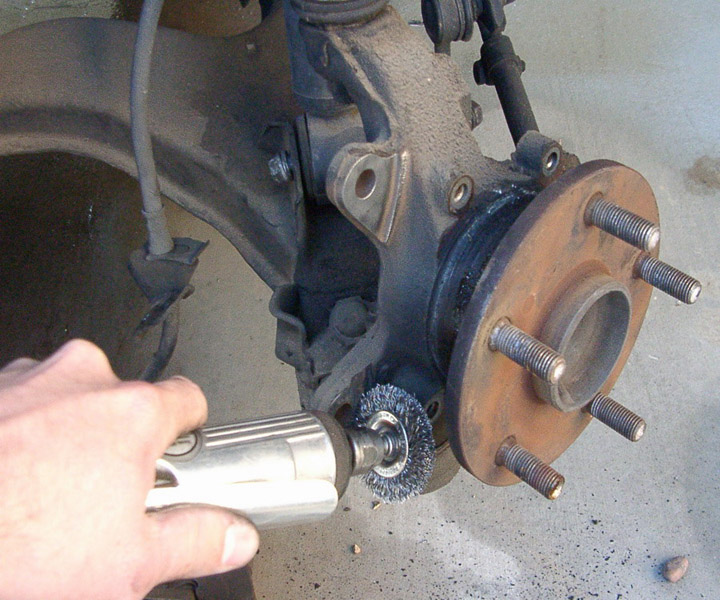
After the mounting surface and the outside diameter of hub mounting surface is clean it should look like this. 05
Remember the rotor hat is hubcentric cleaning that hub/center outside diameter is critical to runout.
THIS STEP IS OPTIONAL, YOU CAN SKIP THIS STEP IF YOU DO NOT WISH TO REMOVE THE DUST COVER ON AN ABS VEHICLE!!!
Next you will remove the rotor dust cover. There are several ways to do this I will cover a few of them
The most difficult and potentially damaging (to the wheel bearings) is to remove the nut for the hub on the back (in board) side of
the spindle. This is the riskiest option, you risk getting dirt in the bearings, you risk damaging the threads, and you risk over
or under torqueing the bearings. It is an option but I do not recommend it. 06, 07, 08, 09
The options I DO recommend will depend on if you have ABS or not. If you have ABS I recommend trimming only the outer dust shield
off of the dust cover assembly ( I say assembly because it is multiple pieces welded together). You can use common aviation tin
snips. Make sure to finish the edges with a file to remove any sharp edges and burrs (prime and paint as necessary). The photo
below shows a non ABS spindle. Notice you can see the fasteners holding the dust cover to the spindle. On an ABS vehicle, the ABS
trigger ring obscures these fasteners and any attempt to gain access to these fasteners using tin/aviation snips risks damaging
that trigger ring. 10, 101
Here is an ABS spindle after removal of the dust cover. You can trim it right down to the outside diameter of the inside flange.
On a non ABS vehicle I recommend loosening these fasteners and trimming a portion of the center out so that the complete dust cover
can be removed. This will avoid tampering with a perfectly good wheel bearing assembly.
In the first photos I snip the inner ring on each side of the fasteners (to provide clearance for the wrench to gain access to the
head of the bolts). Next I use a drift or punch to knock back the inner ring of the dust cover (in front of the fasteners only).
11, 12
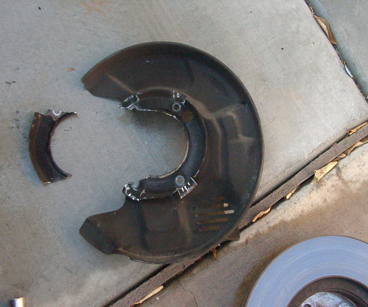
Next I loosen and remove the fasteners holding the dust cover on. Once the dust cover is free I use the snips once again to make a
big opening in the center diameter to slide the dust cover off of the spindle.13,14,
I snip high and low, and the cover comes right off. 15,16,
Next you will need to clean and wire brush the mounting surfaces of the Toyota caliper ears. 17,18
I recommend cleaning the whole spindle but if your pressed for time at least make sure you clean these 3 areas. Again if your not
familiar or not comfortable using these tools please have a professional perform this installation. This portion of the casting
interferes slightly with the installation of your new brake caliper. You will need to clearance this portion of the casting. 19,