
Putting this here as I there is no "electrical" section ")
The toyota IAC is a 6 pole design stepper. Usually labled S1-S2-S3-S4 for the switching ground and B1-B2 for the 12+ vdc. This automatically makes the stepper motor a unipolar designed stepper motor. What this means is that the stepper motor recieves the the energy in only one direction... B1-> S1, B2 -> S2, B1 -> S3
To open the pintle the sequence would be
S4 B2
S3 B1
S2 B2
S1 B1
S4 B2.. x 125
this sequence is controlled by the TCCS. To close the pintle it would be the exact reverse.
S1 B1
S2 B2
S3 B1
S4 B2
S1 B1.. x125
The nice thing about unipolar stepper motors regardless of how many poles it has is that you can make them into a bipolar stepper motor (very important for stand alone ecu's especially if they can control a GM type 4 wire idle motor). Bipolar stepper motors use current flow in opposite directions to open and close the stepper motors. So to use the Toyota IAC as a bipolar stpeer motor you connect the 4 wires from what ever standalone you are using and connect them to pins S1 and S3 for one leg and ping S2 & S4 for the other leg.
what happens now is that to open the pintle, the logic becomes and current flows from
S1 S2
S3 S4
S1 S2
or in other words you are energizing two coil pairs at the same time.
To close (pay attention to the current flow here as this is what make the 6 pole steppers work with only 4 wires connected)
S2 S1
S4 S3
S2 S1 .....
the current flow is REVERSED of what it was during the opening sequence. Hence the name bipolar.
According to all the research I did. The Toyota IAC shows 125 steps but in reality it has close to 255 steps. Also it is quick and if the standalone has adjustments it must be set to at least .25 seconds per step or 4 steps a second.
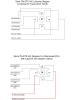
Hopefully the picture attached clears any confusion up
edit: after looking at the schematic, reuploaded a more clear one.
The toyota IAC is a 6 pole design stepper. Usually labled S1-S2-S3-S4 for the switching ground and B1-B2 for the 12+ vdc. This automatically makes the stepper motor a unipolar designed stepper motor. What this means is that the stepper motor recieves the the energy in only one direction... B1-> S1, B2 -> S2, B1 -> S3
To open the pintle the sequence would be
S4 B2
S3 B1
S2 B2
S1 B1
S4 B2.. x 125
this sequence is controlled by the TCCS. To close the pintle it would be the exact reverse.
S1 B1
S2 B2
S3 B1
S4 B2
S1 B1.. x125
The nice thing about unipolar stepper motors regardless of how many poles it has is that you can make them into a bipolar stepper motor (very important for stand alone ecu's especially if they can control a GM type 4 wire idle motor). Bipolar stepper motors use current flow in opposite directions to open and close the stepper motors. So to use the Toyota IAC as a bipolar stpeer motor you connect the 4 wires from what ever standalone you are using and connect them to pins S1 and S3 for one leg and ping S2 & S4 for the other leg.
what happens now is that to open the pintle, the logic becomes and current flows from
S1 S2
S3 S4
S1 S2
or in other words you are energizing two coil pairs at the same time.
To close (pay attention to the current flow here as this is what make the 6 pole steppers work with only 4 wires connected)
S2 S1
S4 S3
S2 S1 .....
the current flow is REVERSED of what it was during the opening sequence. Hence the name bipolar.
According to all the research I did. The Toyota IAC shows 125 steps but in reality it has close to 255 steps. Also it is quick and if the standalone has adjustments it must be set to at least .25 seconds per step or 4 steps a second.
Hopefully the picture attached clears any confusion up
edit: after looking at the schematic, reuploaded a more clear one.
Attachments
Last edited: