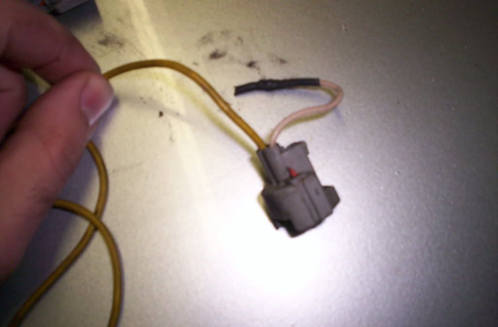
If you look at the wires on the injectors and clips, there should be 1 wire that is all the same color. That wire would be power. The other wire is ground that is supply by the PCM. Since there is only 4 wires coming out of the resister pack. 1 should be getting power to the resister pack while the other 3 should be power coming out of the pack. What you would want to do is either solder all of the same color wires on the injectors [harness side] to 1 different colored wire on the resister pack. Either that or solder 1 of the wire to the pack and cover up the rest. This supply power to the resister pack. The other 3 wires would power the injectors, What you would need to do is group 2 injectors together. Say 1&2, 3&4, 5&6. Each group would get a power source from one of the wire coming out of the resister pack.
Someone correct me if I'm wrong.
But if what you're saying is, you have power to the pack going into the clips. One wire on each clip is cut. That cut wire would be the ground wire going to the PCM.

")