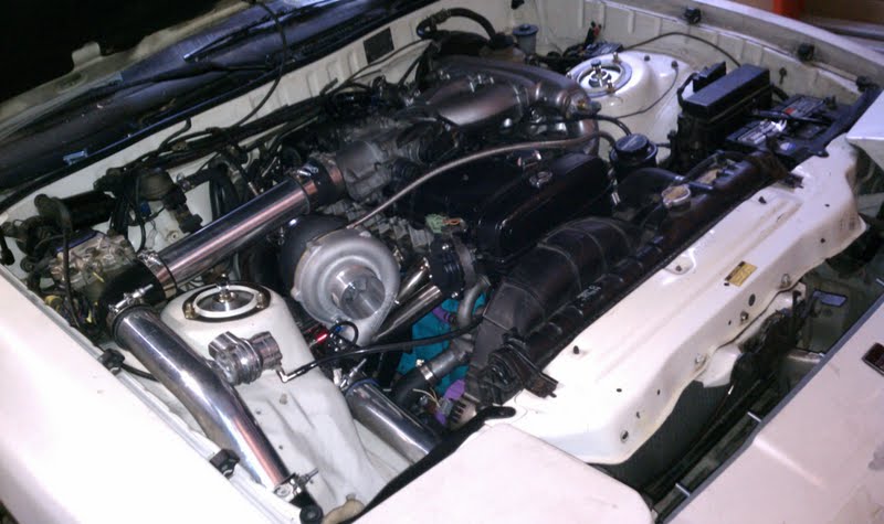
So I am about to install from scratch this Stinger on my 2JZGE swap. I would like a few tips from those whom have had first hand experience with the stinger wire up as all I have to assist me is page 11 of the PDF ") .
.
I have already set the motor to TDC verified that the cams and crank marks are all lined up correctly.
I have removed the JZ distributor and replaced it with the 7M CPS.
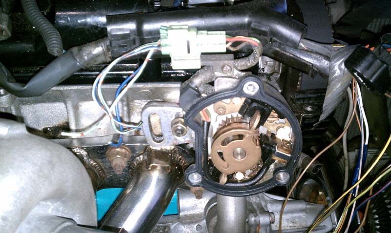
At TDC I lined up the marks on the CPS abd slid it into the head so when it seated it rotated down and the trigger wheel is now lined up with the CPS internal trigger points.
I have also Identified the CPS plug to be #1-Green (NE), #2-Red (G1), #3-Yellow (G2), #4-Brown (G). From my research on SM, G1 is #1@TDC, G2, #6@TDC, NE tooth counter, G is ground.
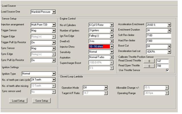
I am looking on the Stinger diagram and included harness... and there are 4 wires, red, blue, green, yellow in a shielded cable. I am not quite sure how they match up. Blue is ground (G), Green is trigger (NE?), Yellow is synch, Red is not used as the OEM 2J sensor is magnetic not 8v hall?
Am I correct so far?
The TPS I can figure out as only 3 of the 4 wires are used from a Toyota sensor. (5v, signal, Gnd)
For the Injectors:
I am using oem High Impedance 2JZGE injectors for now. Do you just use the two primary Injector wires (yellow and white) and wire in three injectors per channel in parallel? Any particular order needed? I assume the Stinger controls ground and the other end of the injectors all collect and go to a (+) on relay.
Any tips you can suggest will help me a great deal, and will be appreciated.
.I have already set the motor to TDC verified that the cams and crank marks are all lined up correctly.
I have removed the JZ distributor and replaced it with the 7M CPS.
At TDC I lined up the marks on the CPS abd slid it into the head so when it seated it rotated down and the trigger wheel is now lined up with the CPS internal trigger points.
I have also Identified the CPS plug to be #1-Green (NE), #2-Red (G1), #3-Yellow (G2), #4-Brown (G). From my research on SM, G1 is #1@TDC, G2, #6@TDC, NE tooth counter, G is ground.
I am looking on the Stinger diagram and included harness... and there are 4 wires, red, blue, green, yellow in a shielded cable. I am not quite sure how they match up. Blue is ground (G), Green is trigger (NE?), Yellow is synch, Red is not used as the OEM 2J sensor is magnetic not 8v hall?
Am I correct so far?
The TPS I can figure out as only 3 of the 4 wires are used from a Toyota sensor. (5v, signal, Gnd)
For the Injectors:
I am using oem High Impedance 2JZGE injectors for now. Do you just use the two primary Injector wires (yellow and white) and wire in three injectors per channel in parallel? Any particular order needed? I assume the Stinger controls ground and the other end of the injectors all collect and go to a (+) on relay.
Any tips you can suggest will help me a great deal, and will be appreciated.
Last edited: