Oil Catch Can / PCV question

89MkIII

targa'd tank
Mar 30, 2005
147
0
0
WI
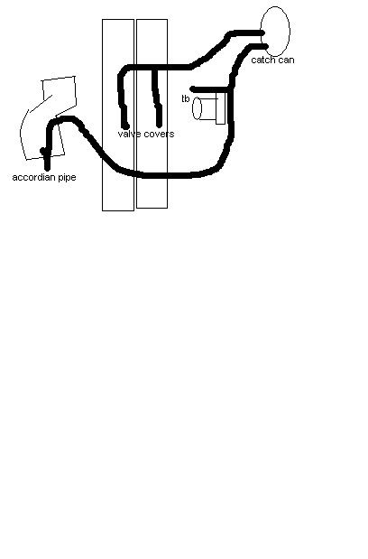
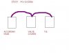
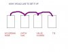
I've done my searching homework on this topic and I'm not sure if I'm missing something obvious here. The majority of the threads on this subject all say people are setting up catch cans incorrectly on the 7M and that the best setup is keeping it stock. There are 3 attachment points on the stock pcv system (valve covers, TB, and Accordian hose). If you maintain all 3 points and insert a catch can in between the stock PCV piping and the accordian hose.......... how could anything be effected negatively? (FYI. The catch can is a cusco and has 2 ports.)

It appears to me like the majority of people do this, BUT they disconnect the TB vacuum source by directly connecting the catch can via hoses or N/A PCV pipe and then capping the TB vacuum.

1. Would this setup (see picture) be an improvement from stock? Mind - I do have some minor blow by.

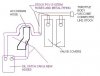
2. I have one available mounting place for my catch can directly (touching) the windshield washer fluid reservoir. I know the ideal location is on intake side by the master clutch slave... but there is no room there. It appears this location by the air filter would be a pretty cool (no pun intended) spot to put it compared to sitting directly next to the engine (either side) and/or turbo. Will this work as an alternative (next best thing)?
 

Attachments

  • PCV.JPG
    PCV.JPG
    24.9 KB · Views: 114
Last edited:

marc3

canadian blood
Jul 19, 2006
229
0
0
quebec,canada
no...bad:umno: here is the way!
p731078_1.jpg
 
Apr 1, 2005
254
0
0
WA
the way marc posted is the best compromise and is the way it is plumbed up stock, only difference being the addition of the catch can.

the idea of the pcv system is to have a vacuum on the crankcase to remove blowby gasses and to a smaller extent, lessen windage. without the vacuum, any blowby would cause a positve pressure in the crankcase and would lead to leaky seals. the blowby also contains fuel vapor witch will contaminate your oil if not removed.

the supras crankcase is connected to the valve cover (by the big hose just behind the alternator) so venting our valve covers means venting our crankcase. now you could simply vent it, and some here do, however that would not produce a vacuum and therefor would not remove the blowby vapor. of course, it would remove the excess pressure to make your seals happy, but your oil will eventually become contaminated with fuel. not ideal.

the stock config. uses two vacuum sources, the intake manifold and the pre- turbo intake. the manifold is a great vacuum source UNTIL you start making boost. the pre-turbo intake produces next to zero vacuum until you are at WOT. at WOT, it produces a small amount of vacuum. between 0.5 - 1.0 in/Hg. compare that to the ideal vacuum of 14-15 in/Hg. so you can see even the stock config is nowhere near ideal, unfortunately, the only better solution is a belt driven pump, and those are expen$ive and tend not to last.

so you can cap off the manifold line if you want, BUT why would you want to? its the only decent vacuum source we've got. its highest vacumm when we dont need it as much (at idle) and zero vacuum when we really want it (at WOT), but IT IS vacuum. and i for one am going to take advantage of it.

if you want to read more, some honda guy did a bunch of tests on this stuff. you can read his thread here. http://www.honda-tech.com/zerothread?id=1199935
 

89MkIII

targa'd tank
Mar 30, 2005
147
0
0
WI
screaminglemon said:
the way marc posted is the best compromise and is the way it is plumbed up stock, only difference being the addition of the catch can.

Correct me if I'm wrong, but wouldn't the following diagram be the stock setup? Also, with the original post's diagram it may have looked like I'd tapped into the accordian hose twice, I did not mean for that *now corrected. I also never planned on capping off the intake manifold(TB) vacuum, but was just saying it appears like a lot of other people do it and that it is not the best route to take.

I assume what you are saying is wrong w/ my setup is that oil vapor, to some degree, will still get sucked into the intake manifold because the catch can is in between the two vacuum sources. With Marc's diagram, both vacuum sources are pulling the oil vapor into the catch can?? If that is correct, it will be a pain in the ass to route it that way because you'll have to T into the TB vacuum. I can see how my idea would not be the absolute ideal, but how can it not be more efficient than stock.... it would be catching some oil as opposed to the stock setup?
 

Attachments

  • STOCK.JPG
    STOCK.JPG
    11 KB · Views: 50
  • CATCH.JPG
    CATCH.JPG
    13.2 KB · Views: 50
Last edited:

jdub

Official SM Expert: Motor Oil, Lubricants & Fil
SM Expert
Feb 10, 2006
10,730
1
38
Valley of the Sun
Marc3's diagram is the best (and correct) way. You want vac on one side of the can to pull vapor from the cam covers through the can so they can condense there. The way you want to do it will pull most of the vapor straight into the TB off boost (since manifold vac is much stronger). I agree that NOT capping off the TB fitting is what you want to do and will most closely replicate the stock set-up.

BTW - you want the can located away from the hot side (exhaust manifold & turbo) of the motor. The can needs to be relatively cool for vapor to condense...othewise you will pull vapor through the can and accomplish little.
 
I don't quite get that last setup as the goal is to reburn the vapors in the engine thereby eleminating the hydrocarbons, but by just sending the fumes into the exhaust... I guess some will burn due to the heat, but I think that would just be sending blowby gases out the pipe and into the air. The worst setup I've seen is breathers on the covers that eventually get full of oil and then create a vapor barrier and eventually a blown seal.
Marc3's diagram is perfect and is exactly what I've setup.
 

mmarkk

ShoarmaTeam Member
Apr 12, 2005
89
0
0
The Netherlands
A guy here(Arnout) mounted this system to a few mk4's, but with manifold vacume added
He said the oil cap was hard to get off because of the vacume:)
 
Apr 1, 2005
254
0
0
WA
89MkIII said:
Correct me if I'm wrong, but wouldn't the following diagram be the stock setup?
yes. but all the diagrams so far are some form of the stock setup. the only differences are the location of the catch can.

89MkIII said:
I assume what you are saying is wrong w/ my setup is that oil vapor, to some degree, will still get sucked into the intake manifold because the catch can is in between the two vacuum sources. With Marc's diagram, both vacuum sources are pulling the oil vapor into the catch can??
correct

89MkIII said:
If that is correct, it will be a pain in the ass to route it that way because you'll have to T into the TB vacuum.
correct

89MkIII said:
I can see how my idea would not be the absolute ideal, but how can it not be more efficient than stock.... it would be catching some oil as opposed to the stock setup?
yes, and if you needed to choose between putting a can between the pre-turbo intake/cam cover or between the manifold/cam covers, then the former is the better choice as it would reduce the amount of oil in the intercooler. but the inside of your manifold would become an oily mess in notime.
 
Apr 1, 2005
254
0
0
WA
mmarkk said:
i think this system looks great, no silly can and just 2 hoses

newebay242.jpg
MDCmotorsports said:
^ That system is also ideal with the exception of cars that have to pass emissions.
i wouldnt call it ideal, but it can work. an exhaust slashcut like this will pull very little vacuum at idle (up to 0.4 in/Hg) and under load will oscillate unpredictably between 1 - 2 in/Hg with some periods of positive pressure. thats why there are those big check valves in that system, and is also the reason you would want to also use a breather in combination with an exhaust slashcut. the numbers might improve if you are running straight pipes with no muffler.

thelonerider said:
I don't quite get that last setup as the goal is to reburn the vapors in the engine thereby eleminating the hydrocarbons, but by just sending the fumes into the exhaust...
this depends on your goal. the pcv systems in the 50's were simply an open tube run to the bottom of the engine bay. the air passing by would create a slight vacuum. this is the same principal but it dumps into the exhaust pipe. tomato, tamato. in the 60's and 70's automakers where required to control the imissions so they created a closed pcv system to burn the gasses in the combustion chamber.

but controlling emissions is only one funtion of the pcv system. the main one being to relieve the pressure caused by blowby. then to actually remove the blowby to prevent oil contamination. and if you have enough vacuum, you can even increase horsepower by reducing the windage effects. thats why you see alot of drag cars sporting belt driven vacuum pumps.
 

starscream5000

Senior VIP Member
Aug 23, 2006
6,359
0
36
Hot and Humid, KY
Thanks for the emailed pic Brian! (whoever you are)

The first pic I've quoted is indeed the way I was thinking the catch can setup should run, as I've described that picture in words before, yet never recieved a definite "yes" or "no" on if it was the correct way.
 

CRE

7M-GE + MAFT Pro + T = :D
Oct 24, 2005
3,485
0
0
Denver, CO
starscream5000 said:
Thanks for the emailed pic Brian! (whoever you are)

The first pic I've quoted is indeed the way I was thinking the catch can setup should run, as I've described that picture in words before, yet never recieved a definite "yes" or "no" on if it was the correct way.

definite "yes"