No Start button and Fuel pump wiring

GC89

1J-THIS
Jun 13, 2007
938
3
18
38
Spokane, WA
I have been planning on switching to a MKIV pump for quite a while now but want to keep the stock hi low pressure system.

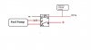
Diagram is at the bottom using a 30a bosch relay. I think I have the relay system worked out all I have left to decide on is how to limit the pump speed for low flow. Either a resistor, in which case I need to decide on which value. Factory is .7 I believe which provides 10-10.5v or so and should be enough to run the pump I think. Or to use a PWM to limit the speed. Any opinions for either?

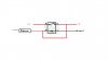
I also want to put a no start button in for security. i have the factory headlight washer button from a pre-89 and figured it would make it nice and low key. I have the diagram I was thinking of also posted below. I wasnt sure what to interrupt though as there are obviously several way to do it an would like opinions. I was leaning towards starter kill for convenience so I could still switch on the accessories without having to push it, just to start.
 

Attachments

  • Kill Switch..jpg
    Kill Switch..jpg
    11.9 KB · Views: 17
  • FP_Circut..jpg
    FP_Circut..jpg
    14.1 KB · Views: 20

GC89

1J-THIS
Jun 13, 2007
938
3
18
38
Spokane, WA
Thanks, I remember seeing your older thread but that one is much more helpful. Your set up looks basically the same as what I plan to do. Nice idea on the y to maintain diagnostic function. So what value of resistor did you choose and why that over a pwm? Any complaints or difficulties tuning around the switch point?

Any input from anyone who has installed a kill switch or a description of how they did it?
 

GC89

1J-THIS
Jun 13, 2007
938
3
18
38
Spokane, WA
Dont know why I had never though of that JJ, that would be a simple option.

Isnms, after looking your diagram over again, did you wire your relay system as well as leave the stock wiring? What supplies power at low load settings? I realized my system needs another relay even as is otherwise the pump would be running constantly, or I would need to incorporate some of the stock wiring. Maybe leave the factory wiring for low load and run 10ga for high. I just want it to be as simple as possible and I though designing my own all in one relay board or set up would make it more simple.
 

reincaster

New Member
Dec 25, 2009
68
0
0
Guam
jetjock;1523345 said:
Since you're messing with that circuit anyway my recommendation is to disable the pump, not the starter...

I agree, just disabling the starter doesn't do much, thieves can still pushstart it if they're desperate.
 

GC89

1J-THIS
Jun 13, 2007
938
3
18
38
Spokane, WA
Ok I did a new and much more detailed diagram including the fuel pump interupt circut. With this method I could either use the stock fp relay and resistor and just trigger an additional relay to provide 12+v at high load. Or just the fp relay with my own resistor set up. Im also wondering if diodes would be required in the switch circut, I put ? in the diagram near the areas in question.

Does this look ok to you JJ, also do you have any knowledge of the TT pump and do you think that a .7 resistor would provide enough to power it at low load?
 

Attachments

  • Fuel_Pump_Circut+&.GIF
    Fuel_Pump_Circut+&.GIF
    54.7 KB · Views: 8
Last edited:

isnms

United States of America
Mar 30, 2005
2,145
0
36
Oklahoma
i80.photobucket.com
These two reasons were why I decided not to pursue the low voltage option:


• the .7 ohm resister will drop to much voltage making the mkiv pump bog
I could not find the proper resistor.​

• with modifications - the calibration of the ecu switch point is off
The stock ECU switch point may not meet system requirements when modifications are made, i.e. upgraded turbo, intake, injectors,...​
 

GC89

1J-THIS
Jun 13, 2007
938
3
18
38
Spokane, WA
Im not to worried about the switch point, from my testing with an multimeter the ecu switches over pretty easily. I was also going to wire in an override switch so I can switch to high load if Im planning on boosting, hard driving ect. Im having the same problem finding a resistor that will handle 30a or even a 12v pwm that will handle 30a, anyone have any suggestions? isnms did you do any testing with the factory resistor and the pump? When I checked with the multimeter it provided 10.5 or so volts which should be enough to power the pump according to some of the flow sheets I have seen. At 12v and .7 ohm resistance you should get around 17 amps, you mentioned 21amp peak spikes in the pump draw so the start up draw of the pump could be the only issue. Consider the 13-14 or so amps a good battery will put out and you have 18.5-20 amps, this is of course in a perfect circut with no other resistance present so giving it a shot might be the only option.
 

GC89

1J-THIS
Jun 13, 2007
938
3
18
38
Spokane, WA
I decided to go with a simpler and more tunable route. I think I am going to ditch the idea of incorporating the stock switching point. Instead I will just rout the power to the pump through a pwm. The pwm's output will be controlled by a voltage input coming from a map sensor. I was thinking a GM 2 bar would work best. I can design the pwm to go from 20-30% at 0v to 100% by say 2v which should be around 40kpa or roughly 6 psi. This will give a nice smooth and linear transition and will be just as simple as my original circuit. It will also be easy to incorporate a over-ride switch by simply having it supply 2v to the pwm when closed. I did some research on a circuits forum and was recommended the pwm design below. The only issue is it has no values so If anyone could help me out in calculating them I would really appreciate it.
 

Attachments

  • PWM_diagram..pdf
    399.6 KB · Views: 5
  • FP_Circuit..bmp
    794.2 KB · Views: 4
Oct 11, 2005
3,815
13
38
Thousand Oaks, CA
I have been planning for a MK4 pump swap as well.

The MK3 low speed circuit uses a 0.7ohm resistor to drop the pump voltage from 14V to 10V (at least that is what my numbers are). That corresponds to a low speed pump current of 5.7A.

The MK4 pump (based on published data from John Cribb) can be expected to draw about 10.4A at 10V with a 40psi head, about double the MK3 pump current.

Therefore, my simple plan to retain the dual speed design is to put two MK3 resistors in parallel to give a 0.35 ohm resistor. That should result in a pump voltage of about 10.25V and a pump current of 10.7 A, which will be fine.

The wiring is the next issue. The stock wiring for the pump is 2.0 mm diameter, which is more or less equal to 12AWG wire. This should be good for 20A for the lengths we are considering. The main issue is the 15A fuse in the EFI circuit. For 25psi boost you would expect to need 60-70 psi at the pump, which is going to be 16-17A pump current.

My proposed solution to this is to rewire the COR on its own 20A fused circuit. I have not looked at the actual feasibility of doing this change, so depending on the location of junctions and so on may come up with a different plan when I actually look into it more closely.

The resistance of 20ft of 12GA is 0.031 ohms, so at 17A we would expect to see a drop of about 0.5V. That would give ~13.5V at the pump, or about 210L/h at 70 psi, enough for 550CC injectors at 100% duty.