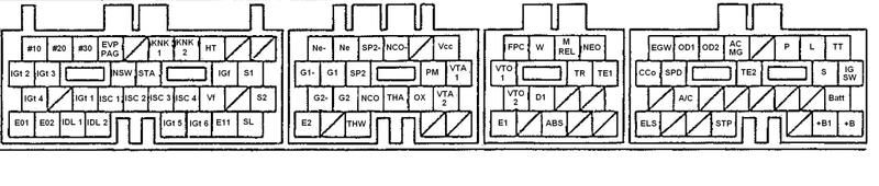
I'm in the process of making a patch harness for a JZA70 harness to JZZ30 ecu, and I have a few questions. On the pinout diagrams that I used, there were slight differences to what each pin is abbreviated to, for example PM is map sensor on the JZZ30 diagram and PIM is map sensor on the JZA70 diagram so I want to make sure that these are correct.
PM on the JZZ30 ecu is same pinout as PIM on the JZA70 ecu
VCC on the JZZ30 ecu is same pinout as VC on the JZA70 ecu
EVP PAG on the JZZ30 ecu is same pinout as EVP on the JZA70 ecu
Second, the JZZ30 ecu has an extra ground called E11 that the JZA70 doesn't have. Do I just splice into an existing E(x) ground?
And third, where do the FC and FPR pinouts on the JZA70 ecu and PFC and D1 pinouts on the JZZ30 ecu go?
So far I was able to match up the following pins on both ecus
HT
ISC1,2,3, and 4
#10
#20
#30
VF
IGF
IGT1,2,3,4,5, and 6
E1
E2
E01
E02
THA
THW
OX
KNK1 and 2
TE1
TE2
TT
VTA1 and 2
IDL1 and 2
G1+ and -
G2+ and -
NE+ and -
EGW
CCO
BT
BATT
M REL
W
ELS
ACMG
SPD
STA
+B
IGSW
STP
NWS
I would like confirmation that I am on the right track before I start soldering, thanks
Last edited: