This writeup is how I built and installed ms3x in my 90 supra with
full sequential ,launch control , boost control , using stock cps if you choose to follow this writeup you do so at your own risk")
i wish you the best of luck
first I would like to send special thanks to pyro15d, Nathaninwa, and terrencelp you guys were excellent help getting me going
and i would like to thank BryanDyer, 3tc power, and suprajztwenty for assisting me with this writeup
OK,the ecu,
I chose the unassembled ms3 from diyautotune
here are the diy part numbers for all the items I needed
[MS330-K_m4]
*MS330-K kit with MapDaddy4 Upgrade*
(mapdaddy 4 is a 4 bar map sensor that allows for real time barometric correction)
this is the case, base unassembled ms3 ,and map sensor
[MS3Xpander]
*MegaSquirt-III MS3X Expansion Card*
This is the extra card required for full sequential fuel and ignition as well as launch control and a bunch of other goodies
[MS3Knock-K]
*MS3 Knock Module Kit*
This is the knock module you need if you are planning on running knock sensors
[MS3TuneCable]
*USB cable for MegaSquirt-III*
Tuning cable
[MS3X-Harness]
*12' MegaSquirt Wiring Harness for MS3X*
[MSHarness12]
*12' MegaSquirt Wiring Harness (MS1 / MS2 / MS3 Ready)*
(note you do need both of these harnesses)I got these harnesses however they also have 8' harnesses that also work and will need to be trimmed (for both the 12' and the 8' harnesses you will need to purchase extra shielded wire for your knock sensors and the cam input as they do not come from diy shielded
[EBC_Sol_kit]
*EBC Electronic Boost Control Solenoid Kit*
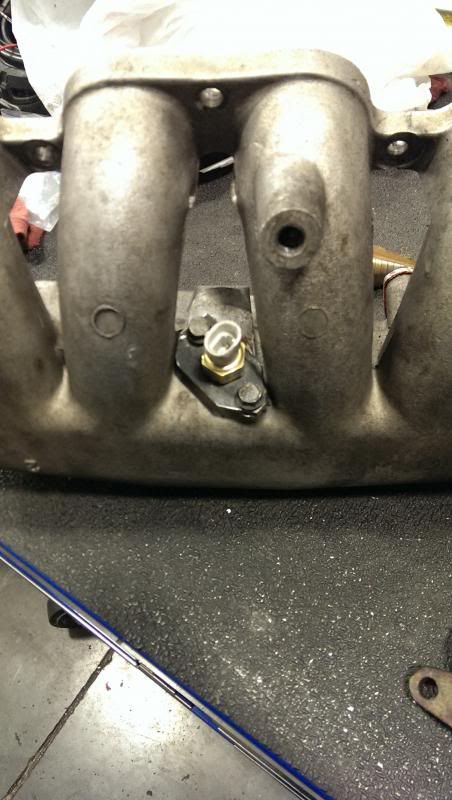
[IATwPiggy]
*GM Open Element IAT Sensor with Pigtail*
[38NPT-Bung_A]
*3/8" NPT Aluminum Weld-On Bung for IAT or CLT Sensor*
I did not use the jimstim, at this point it does not simulate our cps but will help if you run into any problems when you solder your own board together
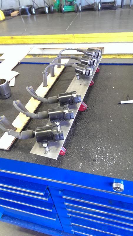
for my build I used ls2 coils, however, these would not work as well with a stock intake manifold, in that case 1zz coils will work fine

I also am using high impedence fuel injectors so I dont use a resistor pack if you are using low impedence injectors you will need to use a resistor pack suprajztwenty has a great description in post #6 in this thread

purchase tunerstudio and megalog viewer its worth it
BOARD ASSEMBLY
http://www.msextra.com/doc/ms3/build_manual.html
as there are different jumpers to install or remove keep in mind if you will be using the stock cps to follow the instructions for VR sensors
and if you are using the stock iacv it will be a 4 wire stepper motor(stock it has 6 wires we will only be using 4 details in the wiring section)
for trigger input use V3.0 VR input (for VR)
on ms3x this is taken from the ms3x website
JP7 is a jumper for a pullup on the "Cam" input. This is typically required with hall or optical sensor inputs. It should NOT be used with VR sensor inputs.*
When using hall or optical sensors inputs, the cam input adjustment potentiometers should be set as follows. Turn both pots (R11 and R32) full anti-clockwise - approx five turns. Then turn the top one (R11) two turns clockwise.*
When using a VR (magnetic) sensor input, the cam input adjustment potentiometers should be set as follows. Turn both pots (R11 and R32) full anti-clockwise - approx five turns. This is usually the right setting.
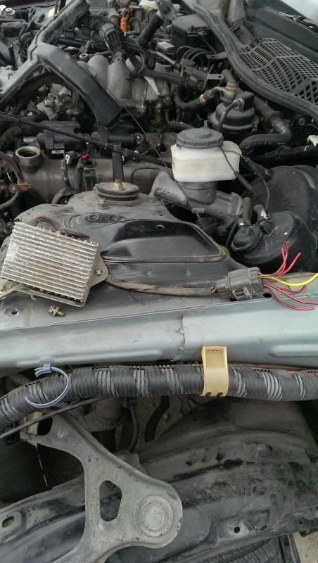
WIRING
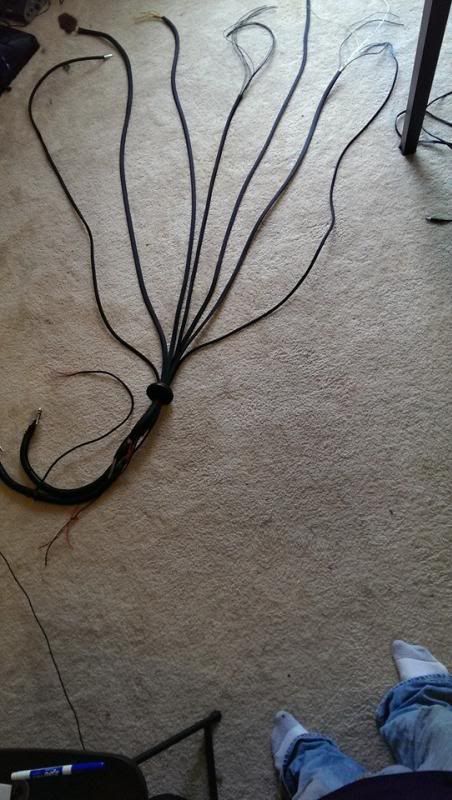
I started by separating my harnesses into (to dash) and (to engine bay)

ENGINE BAY HARNESS (38wires)
all grounds /sensor return(11 wires)
6 spark output wires a-f = LS2 COILS (wire all spark outputs in firing order aka a=1 b=5 c=3 d=6 e=2 f=4)
6 injector outputs a-f =ID 1000CC INJECTORS(high z)(wire all injector outputs in firing order aka a=1 b=5 c=3 d=6 e=2 f=4)
coolant temp=COOLANT TEMP SENSOR(this is a signal wire use sensor ground b/w wire in ms harness for ground)
boost control=EBC(this is a ground wire other side of ebc needs switched 12v)
spr3 (knock input)=KNOCK SENSOR 1(replace with shielded wire)
spr4 (knock input)=KNOCK SENSOR 2(replace with shielded wire)
cam input=CAM POSITION SENSOR(replace with shielded wire)goes to yellow wire on cas
tps sig=TPS(vta stock wire is W/R)
air temp=IAT(this is a signal wire use sensor ground b/w wire in ms harness for ground)
crank sensor=CRANK POSITION Sensor goes to red wire on cas(the other wire in the shielded pair is the ground for both cam and crank sensors and should be attached to the white wire on the cps)
+5v vref=TPS(vcc stock wire is L/R)
12v+ switched=needs to tie into a wire thats going from small gauge b/o in connector (C1) to the small gauge b/o WIRE in connector (B1)*
vvt= i used this to signal my ELECTRIC FAN RELAY
iac1a=w/y wire in cps
iac1b=L/R in cps
iac2a=R/B in cps
iac2b=G/W in cps
the black wire with a white stripe is the sensor ground and needs to go to the ecu coolant temp sensor,the iat sensor and the e2(brown)wire on the tps(note the tps has a 4th wire this is the idl (Y/L)wire and will not be used with the ms)
a couple of the black ground wires need to be used for "signal grounds" on the coil packs
all other grounds need to be grounded to the head preferably in the stock location on the intake manifold
DASH HARNESS (or currently unused)(27 wires)
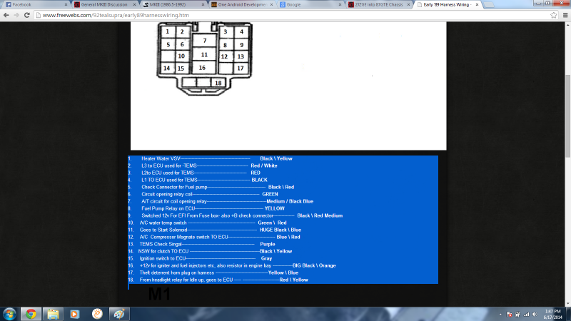
tach output=BLACK WIRE in the (M1) connector
o2sig=WIDEBAND O2 SIGNAL (from your wideband o2)
datalog input=BUTTON ON DASH for datalogging with sd card button needs to be temporary push connected to ground
spr1=UNUSED
spr2=UNUSED
nitrus input=UNUSED
nitrus out=UNUSED
nitrus out 1=UNUSED
spk g+h=UNUSED
inj g+h=UNUSED
fuel pump relay=GREEN WIRE in (B1) connector
pt4 logic output=UNUSED
ext_map=UNUSED
inj bank 1(2wires)=UNUSED
inj bank 2(2wires)=UNUSED
tableswitch in=SWITCH ON DASH* (on off switch connected to ground i use this to switch boost tables but can also be used a variety of different ways
idle valve=UNUSED
pwm idle=UNUSED
flex fuel input=UNUSED
ego2=UNUSED
launch cntrl= tap this wire into the CLUTCH SAFETY SWITCH (make sure you hook this to the side of the switch that only gets grounded when clutch is depressed)
spare adc=UNUSED
spark a (from ms3 connector)=UNUSED
Then add additional wires to the engine bay for the following
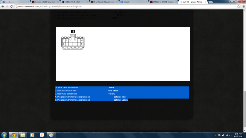
2wires for pps(if equipped) these go from the steering box to the (B3) connector
1 large gauge wire branched to power coils and injectors from large gauge b/o wire in connector b1
3 wires for rear abs speed sensor(if equipped) (from rss to (B3) connector)
1 wire for starter activation (to starter from b/l wire in (B1) connector(or if automatic from neutral start switch)
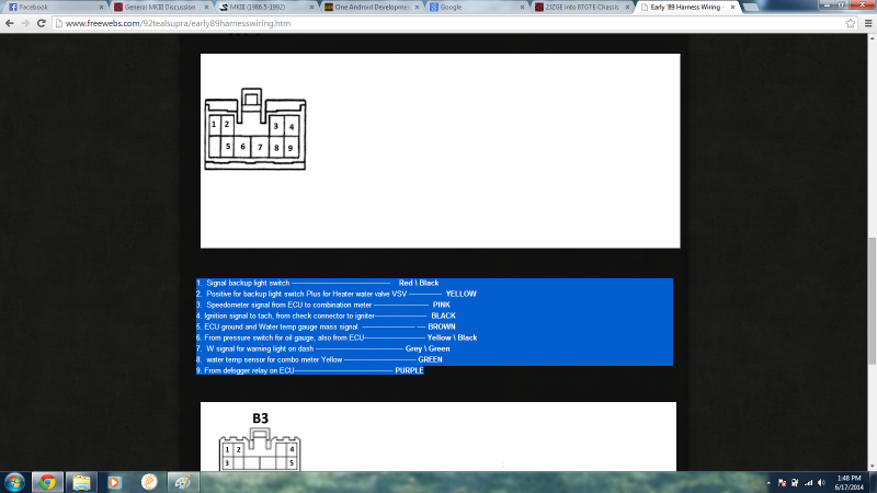
1 wire for coolant temp to stock gauge (y/g in (m1) connector)
1 wire for oil pressure stock gauge (y/b in (m1 connector)
2 wires from c1 to b1 (one is a small gauge b/o wire for mrel which i have already mentioned under 12v+switched) the other gives power to the fp relay and is a b/r wire
2 wires for backup lights from backup light switch in trans to wires y and r/b in the (M1) connector
the cps is the hardest part to get dialed in,
there are a few key points to getting the cps dialed in,
1 every cps i have come across so far (close to 10 off the top of my head do not match the wiring diagrams i have found
so use these,
red is ne(or crank signal coming from the 24 tooth wheel)
yellow is g1(or cam signal coning from the single tooth wheel) using this pickup will mean your tooth 1 angle will be really close to(if not) 20
white is ground(all three sensors in the cps have their grounds tied together inside the cps it is ok to leave it this way
(do not use the green wire)


to clear up the signal you will most likely need to regap the sensors,(I WOULD HIGHLY SUGGEST PULLING THE CPS OUT FOR THIS PART AND SPINNING BY HAND AFTER GAPPING TO ENSURE THAT NONE OF THE TEETH COME IN CONTACT WITH THE SENSORS) take the sensor you are using for the cam signal and the sensor on the 24 tooth wheel and gap them tighter than stock(i used a $20 bill but take caution as i know a guy who snapped a tooth off his cps by gapping it too tight and he also used a $20 bill)
then take the sensor you arent using and gap it as wide as possible to reduce possible crosstalk between sensors
in the ms3x manual here
http://www.msextra.com/doc/ms3/ignition.html
and in the build manual it says turn the 4pots(2on main board and 2 on ms3x board) fully ccw to set them up for most vr sensors
however from what i have seen the best signal is around 6 turns clockwise on the 2 mainboard pots and slightly cw on the ms3x board but this is something you will have to play around with along with the composite logger in ts to dial in for your car
here is a page that i hope will be running soon to help with this http://www.msextra.com/doc/ms3/vrpots.html
STOP!!! BEFORE YOU START YOUR CAR READ THIS AND FOLLOW THE INSTRUCTIONS!!!!!
http://www.msextra.com/doc/ms3/firststart.html
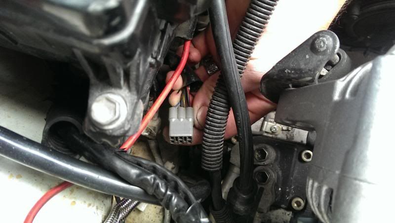
EXTRA PICS


please ask if you need any clarifications
full sequential ,launch control , boost control , using stock cps if you choose to follow this writeup you do so at your own risk
i wish you the best of luck
first I would like to send special thanks to pyro15d, Nathaninwa, and terrencelp you guys were excellent help getting me going
and i would like to thank BryanDyer, 3tc power, and suprajztwenty for assisting me with this writeup
OK,the ecu,
I chose the unassembled ms3 from diyautotune
here are the diy part numbers for all the items I needed
[MS330-K_m4]
*MS330-K kit with MapDaddy4 Upgrade*
(mapdaddy 4 is a 4 bar map sensor that allows for real time barometric correction)
this is the case, base unassembled ms3 ,and map sensor
[MS3Xpander]
*MegaSquirt-III MS3X Expansion Card*
This is the extra card required for full sequential fuel and ignition as well as launch control and a bunch of other goodies
[MS3Knock-K]
*MS3 Knock Module Kit*
This is the knock module you need if you are planning on running knock sensors
[MS3TuneCable]
*USB cable for MegaSquirt-III*
Tuning cable
[MS3X-Harness]
*12' MegaSquirt Wiring Harness for MS3X*
[MSHarness12]
*12' MegaSquirt Wiring Harness (MS1 / MS2 / MS3 Ready)*
(note you do need both of these harnesses)I got these harnesses however they also have 8' harnesses that also work and will need to be trimmed (for both the 12' and the 8' harnesses you will need to purchase extra shielded wire for your knock sensors and the cam input as they do not come from diy shielded
[EBC_Sol_kit]
*EBC Electronic Boost Control Solenoid Kit*
[IATwPiggy]
*GM Open Element IAT Sensor with Pigtail*
[38NPT-Bung_A]
*3/8" NPT Aluminum Weld-On Bung for IAT or CLT Sensor*
I did not use the jimstim, at this point it does not simulate our cps but will help if you run into any problems when you solder your own board together
for my build I used ls2 coils, however, these would not work as well with a stock intake manifold, in that case 1zz coils will work fine
I also am using high impedence fuel injectors so I dont use a resistor pack if you are using low impedence injectors you will need to use a resistor pack suprajztwenty has a great description in post #6 in this thread
purchase tunerstudio and megalog viewer its worth it
BOARD ASSEMBLY
http://www.msextra.com/doc/ms3/build_manual.html
as there are different jumpers to install or remove keep in mind if you will be using the stock cps to follow the instructions for VR sensors
and if you are using the stock iacv it will be a 4 wire stepper motor(stock it has 6 wires we will only be using 4 details in the wiring section)
for trigger input use V3.0 VR input (for VR)
on ms3x this is taken from the ms3x website
JP7 is a jumper for a pullup on the "Cam" input. This is typically required with hall or optical sensor inputs. It should NOT be used with VR sensor inputs.*
When using hall or optical sensors inputs, the cam input adjustment potentiometers should be set as follows. Turn both pots (R11 and R32) full anti-clockwise - approx five turns. Then turn the top one (R11) two turns clockwise.*
When using a VR (magnetic) sensor input, the cam input adjustment potentiometers should be set as follows. Turn both pots (R11 and R32) full anti-clockwise - approx five turns. This is usually the right setting.
WIRING
I started by separating my harnesses into (to dash) and (to engine bay)
ENGINE BAY HARNESS (38wires)
all grounds /sensor return(11 wires)
6 spark output wires a-f = LS2 COILS (wire all spark outputs in firing order aka a=1 b=5 c=3 d=6 e=2 f=4)
6 injector outputs a-f =ID 1000CC INJECTORS(high z)(wire all injector outputs in firing order aka a=1 b=5 c=3 d=6 e=2 f=4)
coolant temp=COOLANT TEMP SENSOR(this is a signal wire use sensor ground b/w wire in ms harness for ground)
boost control=EBC(this is a ground wire other side of ebc needs switched 12v)
spr3 (knock input)=KNOCK SENSOR 1(replace with shielded wire)
spr4 (knock input)=KNOCK SENSOR 2(replace with shielded wire)
cam input=CAM POSITION SENSOR(replace with shielded wire)goes to yellow wire on cas
tps sig=TPS(vta stock wire is W/R)
air temp=IAT(this is a signal wire use sensor ground b/w wire in ms harness for ground)
crank sensor=CRANK POSITION Sensor goes to red wire on cas(the other wire in the shielded pair is the ground for both cam and crank sensors and should be attached to the white wire on the cps)
+5v vref=TPS(vcc stock wire is L/R)
12v+ switched=needs to tie into a wire thats going from small gauge b/o in connector (C1) to the small gauge b/o WIRE in connector (B1)*
vvt= i used this to signal my ELECTRIC FAN RELAY
iac1a=w/y wire in cps
iac1b=L/R in cps
iac2a=R/B in cps
iac2b=G/W in cps
the black wire with a white stripe is the sensor ground and needs to go to the ecu coolant temp sensor,the iat sensor and the e2(brown)wire on the tps(note the tps has a 4th wire this is the idl (Y/L)wire and will not be used with the ms)
a couple of the black ground wires need to be used for "signal grounds" on the coil packs
all other grounds need to be grounded to the head preferably in the stock location on the intake manifold
DASH HARNESS (or currently unused)(27 wires)
tach output=BLACK WIRE in the (M1) connector
o2sig=WIDEBAND O2 SIGNAL (from your wideband o2)
datalog input=BUTTON ON DASH for datalogging with sd card button needs to be temporary push connected to ground
spr1=UNUSED
spr2=UNUSED
nitrus input=UNUSED
nitrus out=UNUSED
nitrus out 1=UNUSED
spk g+h=UNUSED
inj g+h=UNUSED
fuel pump relay=GREEN WIRE in (B1) connector
pt4 logic output=UNUSED
ext_map=UNUSED
inj bank 1(2wires)=UNUSED
inj bank 2(2wires)=UNUSED
tableswitch in=SWITCH ON DASH* (on off switch connected to ground i use this to switch boost tables but can also be used a variety of different ways
idle valve=UNUSED
pwm idle=UNUSED
flex fuel input=UNUSED
ego2=UNUSED
launch cntrl= tap this wire into the CLUTCH SAFETY SWITCH (make sure you hook this to the side of the switch that only gets grounded when clutch is depressed)
spare adc=UNUSED
spark a (from ms3 connector)=UNUSED
Then add additional wires to the engine bay for the following
2wires for pps(if equipped) these go from the steering box to the (B3) connector
1 large gauge wire branched to power coils and injectors from large gauge b/o wire in connector b1
3 wires for rear abs speed sensor(if equipped) (from rss to (B3) connector)
1 wire for starter activation (to starter from b/l wire in (B1) connector(or if automatic from neutral start switch)
1 wire for coolant temp to stock gauge (y/g in (m1) connector)
1 wire for oil pressure stock gauge (y/b in (m1 connector)
2 wires from c1 to b1 (one is a small gauge b/o wire for mrel which i have already mentioned under 12v+switched) the other gives power to the fp relay and is a b/r wire
2 wires for backup lights from backup light switch in trans to wires y and r/b in the (M1) connector
the cps is the hardest part to get dialed in,
there are a few key points to getting the cps dialed in,
1 every cps i have come across so far (close to 10 off the top of my head do not match the wiring diagrams i have found
so use these,
red is ne(or crank signal coming from the 24 tooth wheel)
yellow is g1(or cam signal coning from the single tooth wheel) using this pickup will mean your tooth 1 angle will be really close to(if not) 20
white is ground(all three sensors in the cps have their grounds tied together inside the cps it is ok to leave it this way
(do not use the green wire)
to clear up the signal you will most likely need to regap the sensors,(I WOULD HIGHLY SUGGEST PULLING THE CPS OUT FOR THIS PART AND SPINNING BY HAND AFTER GAPPING TO ENSURE THAT NONE OF THE TEETH COME IN CONTACT WITH THE SENSORS) take the sensor you are using for the cam signal and the sensor on the 24 tooth wheel and gap them tighter than stock(i used a $20 bill but take caution as i know a guy who snapped a tooth off his cps by gapping it too tight and he also used a $20 bill)
then take the sensor you arent using and gap it as wide as possible to reduce possible crosstalk between sensors
in the ms3x manual here
http://www.msextra.com/doc/ms3/ignition.html
and in the build manual it says turn the 4pots(2on main board and 2 on ms3x board) fully ccw to set them up for most vr sensors
however from what i have seen the best signal is around 6 turns clockwise on the 2 mainboard pots and slightly cw on the ms3x board but this is something you will have to play around with along with the composite logger in ts to dial in for your car
here is a page that i hope will be running soon to help with this http://www.msextra.com/doc/ms3/vrpots.html
STOP!!! BEFORE YOU START YOUR CAR READ THIS AND FOLLOW THE INSTRUCTIONS!!!!!
http://www.msextra.com/doc/ms3/firststart.html
EXTRA PICS
please ask if you need any clarifications
Last edited: