Few things bouncing around between the ears..
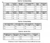
According to the attachment, Stock 440cc injector coils saturate at 2.3-2.4 amps. Theoretically this current would never be reached.
3 ohm resistor pack in series with 2 injectors at 2.9 ohms = Rt 4.45ohm (ideal)
voltage across resistor pack is 9.45v and then 4.56v for the injectors at 14v from alt/batt.
Current It= 3.15a and each injector is seeing roughly 1.58a.
My question is how this current effects aftermarket injectors and latency. RC pl8-550cc's call for 4 amp peak /1.5amp hold and ohm out at 2.9ohms at room temp. Rc tech support said they will work fine with the stock system regardless of the current but did confirm that 4 amps is supposed to be the minimum opening current.
If stock injectors work on a 1.5a peak/.5a hold how would the latency have to be adjusted? thinking increased but current is still limited regardless.
The other option is to change the resistor pack to provide the current the injectors are rated for. Dont know if the ecu drivers can handle more current though.
Maybe im overlooking something, please advise.