
Ive searched, i have all the diagrams, pinouts and information i think i need.. but i have no idea about the actual process involved in splicing the wires and harnesses... if somebody could point me in the right direction or give me some sort of babytalk explanation it would be greatly appreciated... (x73 cressy to jzx90 1j)
I need an idiots guide to wiring an engine.. ive dug myself into a deep hole :(
- Thread starter JP85MX73
- Start date
You are using an out of date browser. It may not display this or other websites correctly.
You should upgrade or use an alternative browser.
You should upgrade or use an alternative browser.
If you're an idiot you shouldn't be wiring an engine.. ")
Some tips I can give from personal experience are:
1) Do NOT splice the wires at all the same length or you will get a big lump in one spot of your harness
2) Please, for love of god, don't use twist caps
3) For a nice clean solder joint, use in-line splices.
http://www.instructables.com/id/Master-a-perfect-inline-wire-splice-everytime/
uhhh. yeah wtf u doing. lol
but if you're wondering how to connect wires and best way. I'd say get a tool that easily strips back the coating and then go here for all connectors. http://www.fastenal.com/web/search/...erminals-and-wire-connectors/_/N-gj4xc3&Nty=0
make sure you label your shit
I've been told that soldering is not that great as the connection can break apart with vibrations. and it made sense...
oh and use a heat gun afterwards and you should be good.
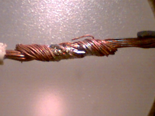
Yblegal91t;1572544 said:I've been told that soldering is not that great as the connection can break apart with vibrations. and it made sense...
Makes sense if your joints look like this:
However, mine look similar to this:
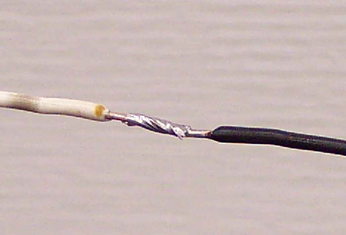
And I have no issues. Use heat shrink afterwords, not electrical tape.. and you'll be golden!
whitemike;1572549 said:However, mine look similar to this:
And your wires are wicked, this can create a stress point that can fail under movement, or vibration. This is the reason many people recommend environmental crimp connections as opposed to solder connections, especially in places like the aviation field. A proper solder connection is not a simple a heating the wire up a slapping solder on there, it takes proper equipment as well as a good amount of practice and patience and is necessary for reliable connections.
Comeon now guys calling someone an idiot and or whatever isn't helpful to him or all that community friendly really. We all gotta start somewhere right?
The truth of the matter regarding automotive wiring as far as my research has been that crimp connections made with a proper crimping tool made for the particular crimps you have is the most ideal way of creating a lasting long term electrical connection in a high vibration environment such as a car.
The trouble with either approach is as Dirgle pointed out, practice and skill definitely are of upmost importance. Simply slapping 2 wires together with a little solider will not suffic for long, as will a badly made poorly done crimp connection either. But crimp connections will outlast solider joints apples to apples in a high vibration environment.
And I would definitely agree with not cutting any number of wires in the same location as the crimps and/or solider connections will tend to bulk up and cause a lump of unmanagable wires that stress each other and lead to failures.
Here's an article I found interesting and helpful when picking a crimp tool. Essentially the cheaper and cheaper the tool the more likely you are going to see poor connections or failure.
http://www.matronics.com/aeroelectric/articles/CrimpTools/crimptools.html
http://www.pbase.com/mainecruising/wire_termination
Last edited:
Dirgle;1572560 said:And your wires are wicked, this can create a stress point that can fail under movement, or vibration. This is the reason many people recommend environmental crimp connections as opposed to solder connections, especially in places like the aviation field. A proper solder connection is not a simple a heating the wire up a slapping solder on there, it takes proper equipment as well as a good amount of practice and patience and is necessary for reliable connections.
Didn't I say 'similar'? Not, here's a pic of my harness? lol
Flateric;1572580 said:Comeon now guys calling someone an idiot and or whatever isn't helpful to him or all that community friendly really. We all gotta start somewhere right?
The truth of the matter regarding automotive wiring as far as my research has been that crimp connections made with a proper crimping tool made for the particular crimps you have is the most ideal way of creating a lasting long term electrical connection in a high vibration environment such as a car.
The trouble with either approach is as Dirgle pointed out, practice and skill definitely are of upmost importance. Simply slapping 2 wires together with a little solider will not suffic for long, as will a badly made poorly done crimp connection either. But crimp connections will outlast solider joints apples to apples in a high vibration environment.
And I would definitely agree with not cutting any number of wires in the same location as the crimps and/or solider connections will tend to bulk up and cause a lump of unmanagable wires that stress each other and lead to failures.
I would like to re-emphasize the importance of the proper crimp tool for the type of crimp your doing. The importance of this one thing cannot be understated.
whitemike;1572581 said:Didn't I say 'similar'? Not, here's a pic of my harness? lol
Granted,looking back you did say that. The picture still shows a poor solder connection, it might have been better to pick a different one for demonstrating what a solder splice should look like.
I could probably point you in the direction of someone that could build you a flawless harness, but if you insist on doing it yourself, youtube how to solder and how to maintain a soldering iron and watch and review as many of these as you can. Then scrounge up some extra wire and practice. When you're confident enough to start on the real deal, go for it. Don't be afraid to fuck shit up, it happens, just do it again. When you're done, check everything for continuity. It should turn out as nice as you feel like making it.
Dirgle;1572587 said:Granted,looking back you did say that. The picture still shows a poor solder connection, it might have been better to pick a different one for demonstrating what a solder splice should look like.
Care to share your demonstration?
JP85MX73;1573356 said:But just to explore options what would it cost for someone to make me a harness anyway?
http://www.phoenixtuning.com/services.html
Dr. Tweak is a member here and a great guy to deal with.
Do it mill spec toyota spec or better dont solder at all use barrel crimped splices like the millitary uses with clear sleave shrink stagger your splices use shield jumpers on all the special sensors such as crank angle cam angle knock o2 sensors dont take short cuts and enjoy splicing over 120 wires 2 times then you will have to do splices for the body connectors and EA2 connectors also.
Or just say screw it all route the wires through the speedo hole then behind the radio with out ruining a 500+ rare engine harness face the ecu to the left instead of right mount it in the factory location drive the car in 2 days.
Does a good wire tuck all you have to do is use the EA2 connector off the fuse block in the front then you only splice 2 wires the one in the jza70 clip. use the EFI & jza70 body connectors splice the 15-30 wires together for your jumper harness plug in your driving in couple days tops.
Evilempire1.3JZ-GTE;1573984 said:Do it mill spec toyota spec or better dont solder at all use barrel crimped splices like the millitary uses with clear sleave shrink stagger your splices use shield jumpers on all the special sensors such as crank angle cam angle knock o2 sensors dont take short cuts and enjoy splicing over 120 wires 2 times then you will have to do splices for the body connectors and EA2 connectors also.
Or just say screw it all route the wires through the speedo hole then behind the radio with out ruining a 500+ rare engine harness face the ecu to the left instead of right mount it in the factory location drive the car in 2 days.
Does a good wire tuck all you have to do is use the EA2 connector off the fuse block in the front then you only splice 2 wires the one in the jza70 clip. use the EFI & jza70 body connectors splice the 15-30 wires together for your jumper harness plug in your driving in couple days tops.
The military uses solder splices. During my time in the Navy I preformed many in the navel aviation field. However the quality standereds were very high, and you had to have a special certification to preform them.
Proper environmental crimp splices like the military uses are very expensive. Typically in the range of $1.00 or more per splice even if you buy them in packs of 100. On a large engine harness the cost can quickly grow.
Much like these:
http://www.aviationlogs.com/PilotShop/proddetail.asp?prod=D-436-36
Evilempire1.3JZ-GTE;1573984 said:Or just say screw it all route the wires through the speedo hole then behind the radio with out ruining a 500+ rare engine harness face the ecu to the left instead of right mount it in the factory location drive the car in 2 days.
Im liking this idea better lol. I do have a chaser harness/engine so my wires are a little longer. i might be able to stretch it inside hopefully, otherwise ill use your idea :evil2:
Dirgle;1573990 said:The military uses solder splices. During my time in the Navy I preformed many in the navel aviation field. However the quality standereds were very high, and you had to have a special certification to preform them.
Proper environmental crimp splices like the military uses are very expensive. Typically in the range of $1.00 or more per splice even if you buy them in packs of 100. On a large engine harness the cost can quickly grow.
Much like these:
http://www.aviationlogs.com/PilotShop/proddetail.asp?prod=D-436-36
We never did solder splice they found solderd wires do not flex then they crack and break.
We used exactly what you show, I have bags of 1000's of them Reds 20-22gauge, Blues 20-18gauge ,Yellows 16- gauge.
The only place they solder is inside the black boxes I believe its called the 67Echo shop that does the soldering in the black boxes WC610 does the blackbox repaires I know I was in the navy and worked for the Navy lemore orlando memphis, army at brag tobyhanna, airforce at simons march air reserve base, marines tustin eltoro pendleton thats off the top of my head anyways do not solder, use enviromental splices as shown here.

using raychem/sargent barrel crimpers

Your supposed to use an IR Raychem laser with mirror to shirnk them down with out burning them or you can use an air/heat gun like the ones harbor frieght sells. They are bright orange use air and a plug in for the heater element. you can vary the heat and airflow you dont want to burn the sleeving just heat it until the red comes out of the end of the sleeve also when you crimp the barrel do both on inspection hole side in the middle make sure you see the wire in the inspection hole.
The only time solder will touch mil spec wiring outside the black box is when shringking the ground shielding sleeve when daisy chaining grounds or doing shield jumpers.
Also very few pins RF Coax some get soldrerd also the PITA 1553 data bus center pins get soldered.
All in all it aint worth it to splice and should be avoided. Ask aaron at driftmotion how many perfect unhacked 1jz harness he haves around and if had one ask him what the price is for one.
I was in the solder shop 69B/C. We were the only shop authorized to use solder splices. Nobody outside of 69B should be doing any soldering unless they are Depo level artisans. They have to be preformed correctly by a certified I-level 2M tech. O-level techs were not allowed to preform them even if they had there 2M cert. The updated NA01-1A-505 manual now references the current NA01-1A-23 manual to allow solder splices within very strict guidelines. This is on all current naval platforms, EA-6B, F-18A/B/C/D/E/F, E2C, ect. That said outside of us only the environmental crimp splices shown above and and their blue and yellow counterparts were allowed to be used, for the exact reasons you stated above.
Evilempire1.3JZ-GTE;1574240 said:.
using raychem/sargent barrel crimpers
Id like to know more about these environmental splices.
The little metal tube is what you crimp to both wires to, right? Then the other part is just shrink-wrap? Do you crimp the wires with the shrink-wrap already in place? Whats the red mark?
I can see how this could work very well for a splice, what would you do if you just wanted to "T" into a wire (like an RPM puckup for instance).
The metal barrel is crimped first on either end for each wire, then the shrink barrel is slipped over it and shrunk down. The colored end is slightly larger to accommodate multiple wires, as in a situation where you "T" into a wire. Also the two ends contain a plastic that becomes semi-fluid during the shrink process, and become solid again after it cools. This allows it to form tightly around the wire insulation and provide an environmental seal, as well as strain relief. Truly wonderful splices, and well worth the cost.
Thanks for the info.
**{thinks to himself}... Now where did i leave that money shovel?**
http://www.store.crimptools.com/search.php?search_query=environmental&submit_search=Search
**{thinks to himself}... Now where did i leave that money shovel?**
http://www.store.crimptools.com/search.php?search_query=environmental&submit_search=Search