First a little background: I have a voltmeter in the dash from a non turbo supra and it always indicated about 12.5 volts even when the battery was charging at 14.2, so I decided to figure out why. I was also experiencing an intermittent click/ no start situation. Upon performing a voltage drop test I found that I was in fact losing approx 1.5V between the battery and the voltmeter. I isolated the ignition switch and found to be responsible for 1 volt of the drop while the engine was running. So I decided to dig in.
Here are the tools you will need:
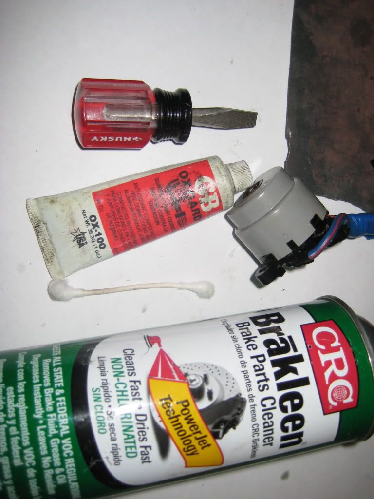
Your ignition switch, a small flat blade screwdriver, a can of brake cleaner or other solvent, a few q-tips, some di-electric grease, and some 600 grit sandpaper.
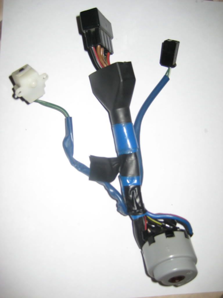
Start by carefully prying the case of the switch open. Just pry all the way around a little at a time to get it free of the tangs, don't force anything since breaking it here will trash the whole thing.
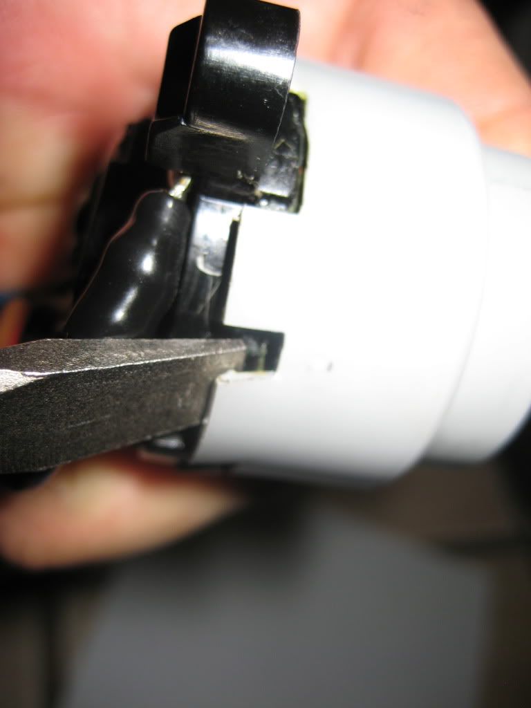
Now once it starts to come apart keep the gray part facing downwards and try to keep the contents inside of that cover. Now Take the two brass contact rings out so it is left looking like this:
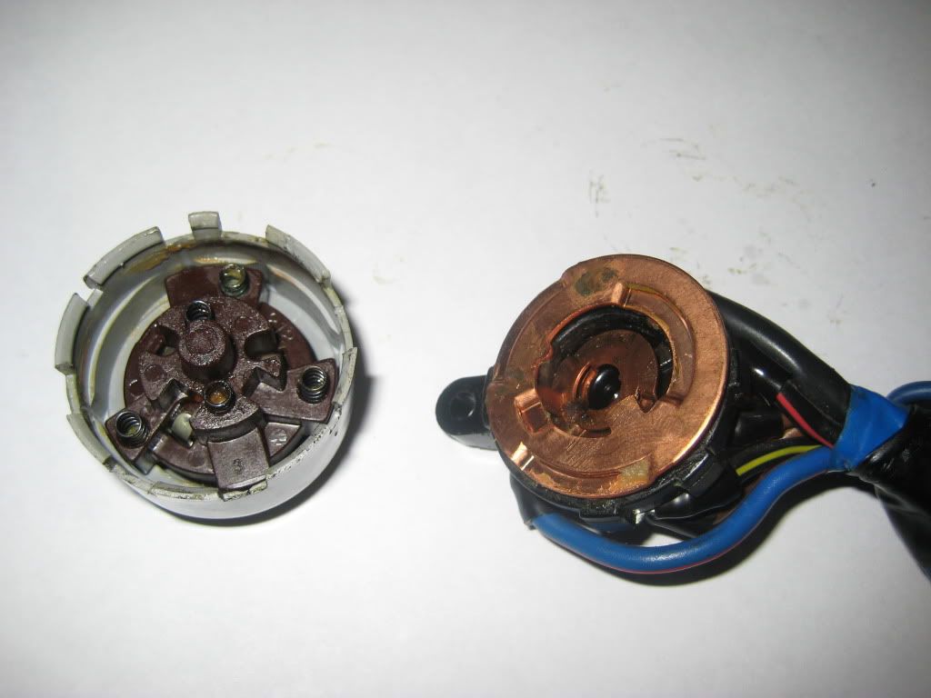
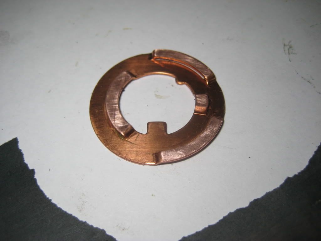
Now grab the two circular copper contact rings and clean all the old grease off. Check the rings for excessive wear, if the copper is worn too badly and is much thinner in the contact areas than the surrounding areas, the switch should be replaced.
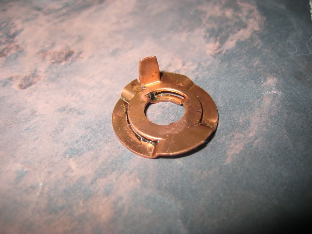
Here is the culprit. That little circle that is worn into the ring was where the contact sat that fed power from AM1 circuit to the IGN circuit.
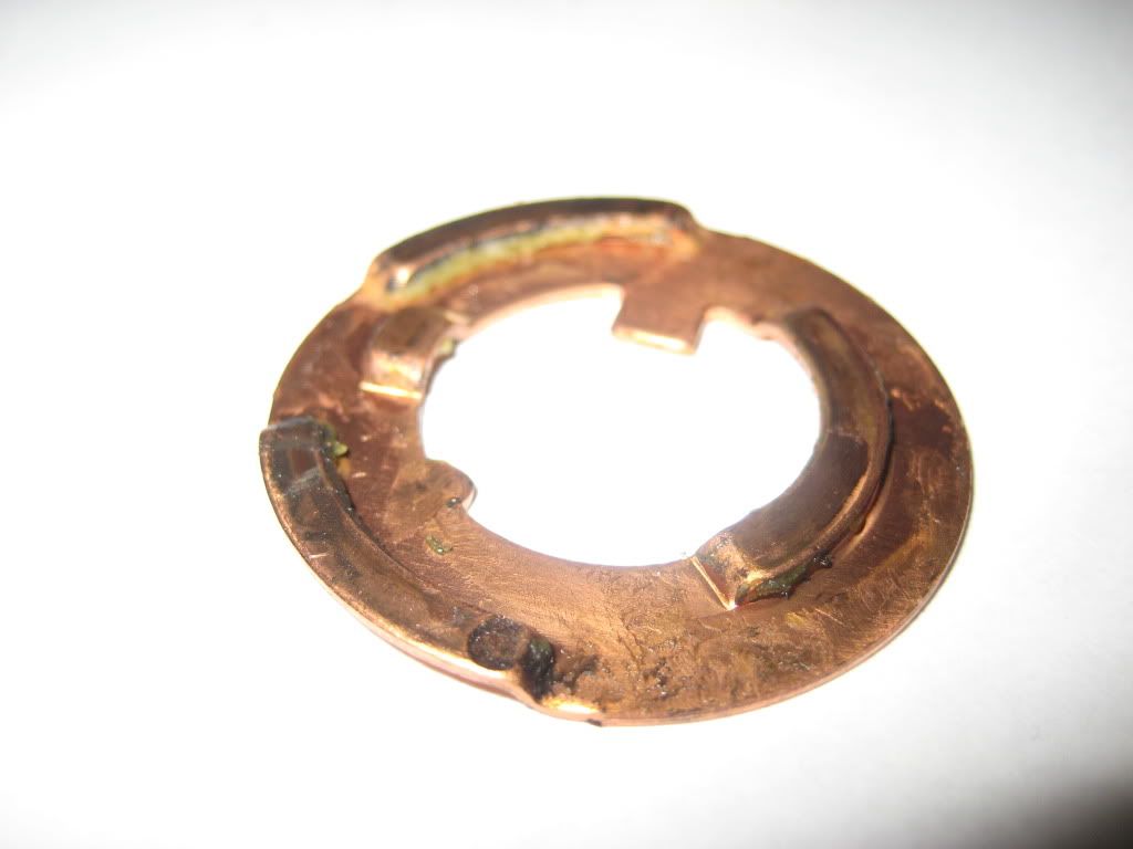
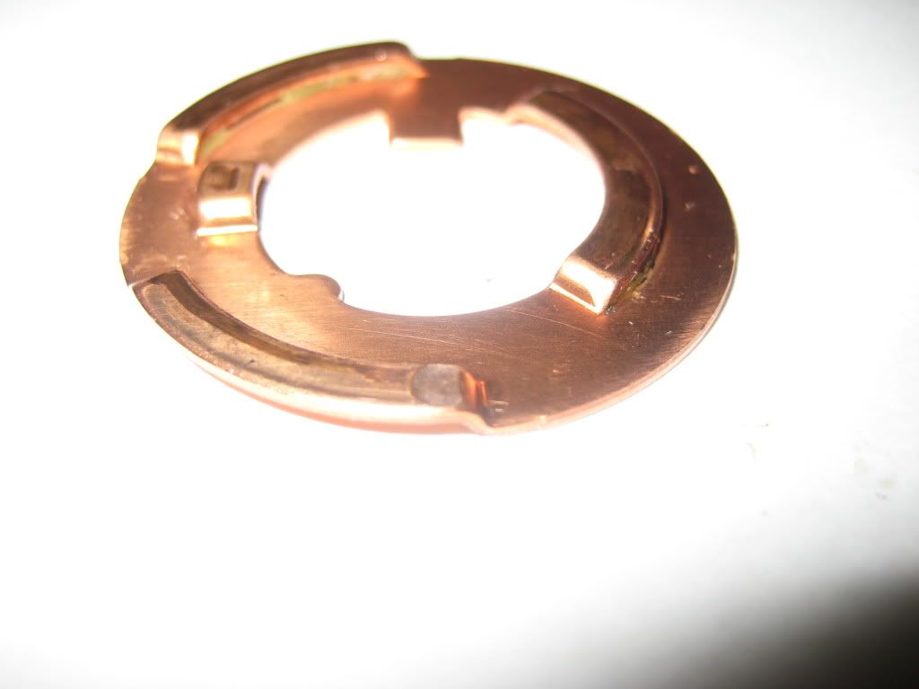
Next clean all the old dielectric grease from all surfaces of the contacts on the rings and the stationary contacts.
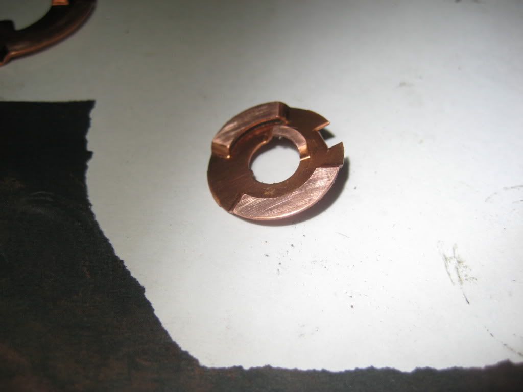
Next, get your 600 grit sandpaper, put it on a flat surface with the grit facing up. Place your larger ring on the sandpaper (raised contact side down, towards the grit) and sand the contacts evenly and a little at a time until you get an even finish all the way across. Only do enough to remove all the pitting and wear marks. Next, do the same thing to your small circular contact ring.
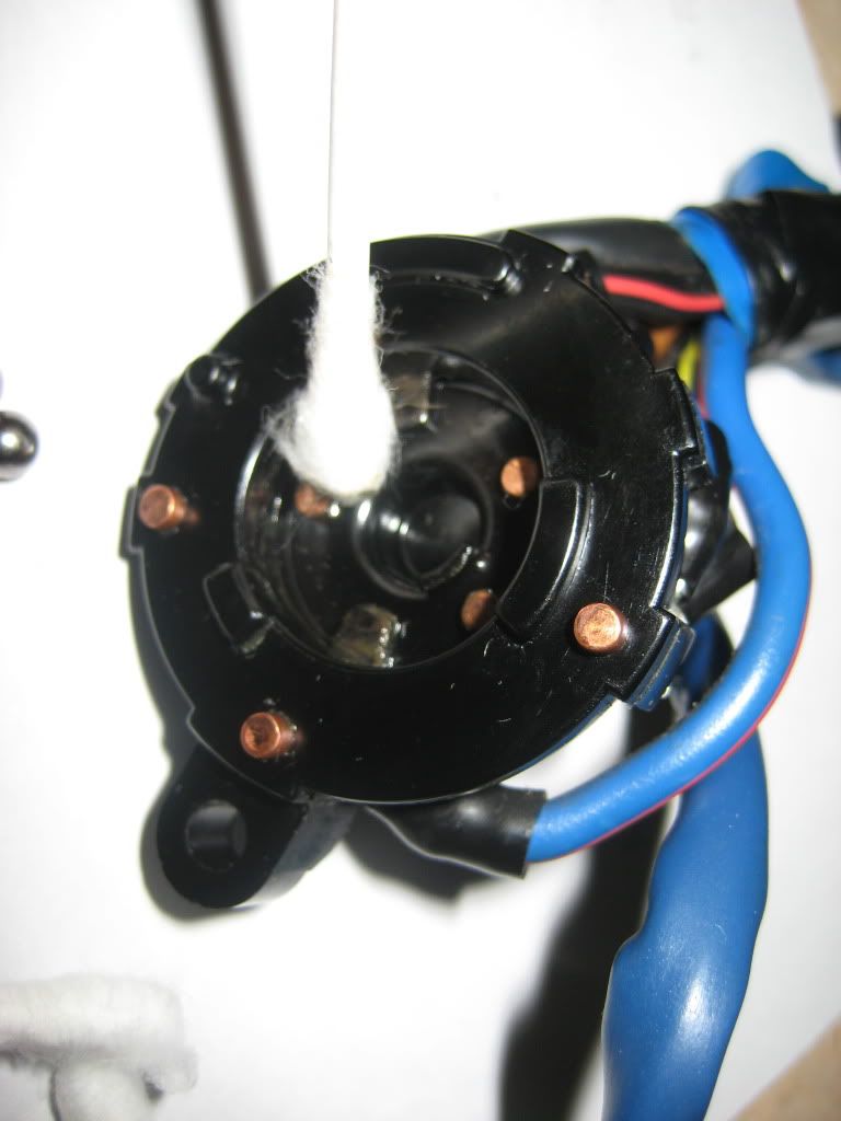
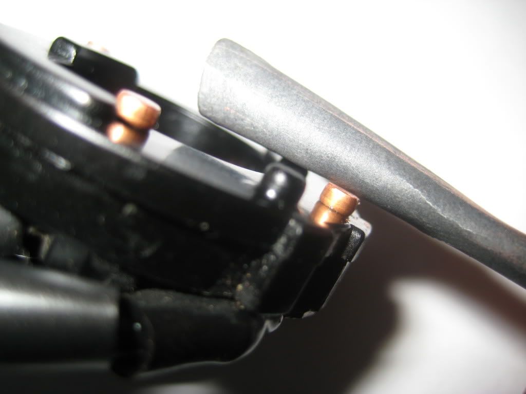
Next, take your screwdriver and wrap some sandpaper around the tip. Use this to take the pitting and oxidization out of the contact pins on the stationary part of the switch. Once again, just enough to get an even surface. You want to try and keep the sandpaper as flat as possible against the contact. When you are done, use the brakeclean to remove any copper filings on the parts and wipe clean.
(This part is optional) Now carefully push the rotor out of the cover while keeping your hand over the parts to (hopefully) catch the detent balls and springs as the two parts come apart. Clean out the old grease inside the cover where the detent balls ride and apply a small amount of new grease to those areas.
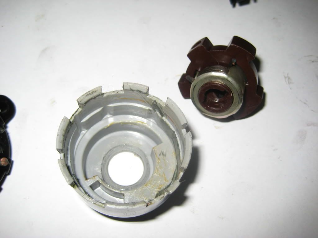
Put your two detent springs back into the holes in the sides of the rotor. Place a ball at the end of each one and squeeze them inward. Carefully insert the rotor into the cover while keeping the balls depressed. Make sure the return spring tangs go into the cover where the 180 degree relief is in the plastic.
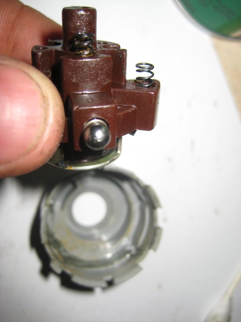
Next look at the brown colored rotor part, and there will be 5 springs, one in each hole. Take the springs out and make sure all are still in good shape, and provide equal spring pressure, none are weak, etc. Place them back into their respective holes.
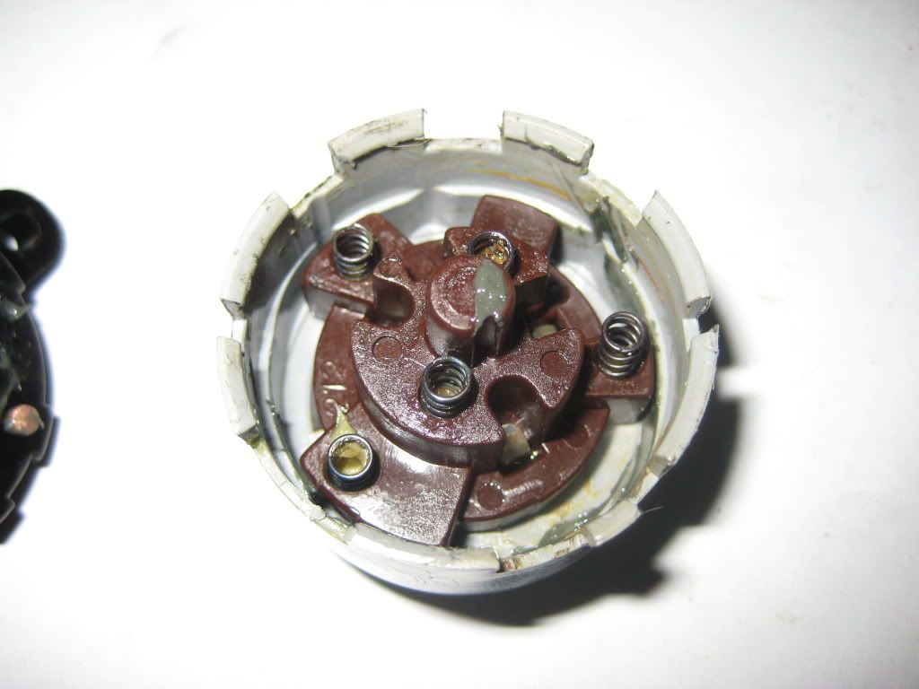
Now you should be left with all your contacts filed down and all parts clean and dry.
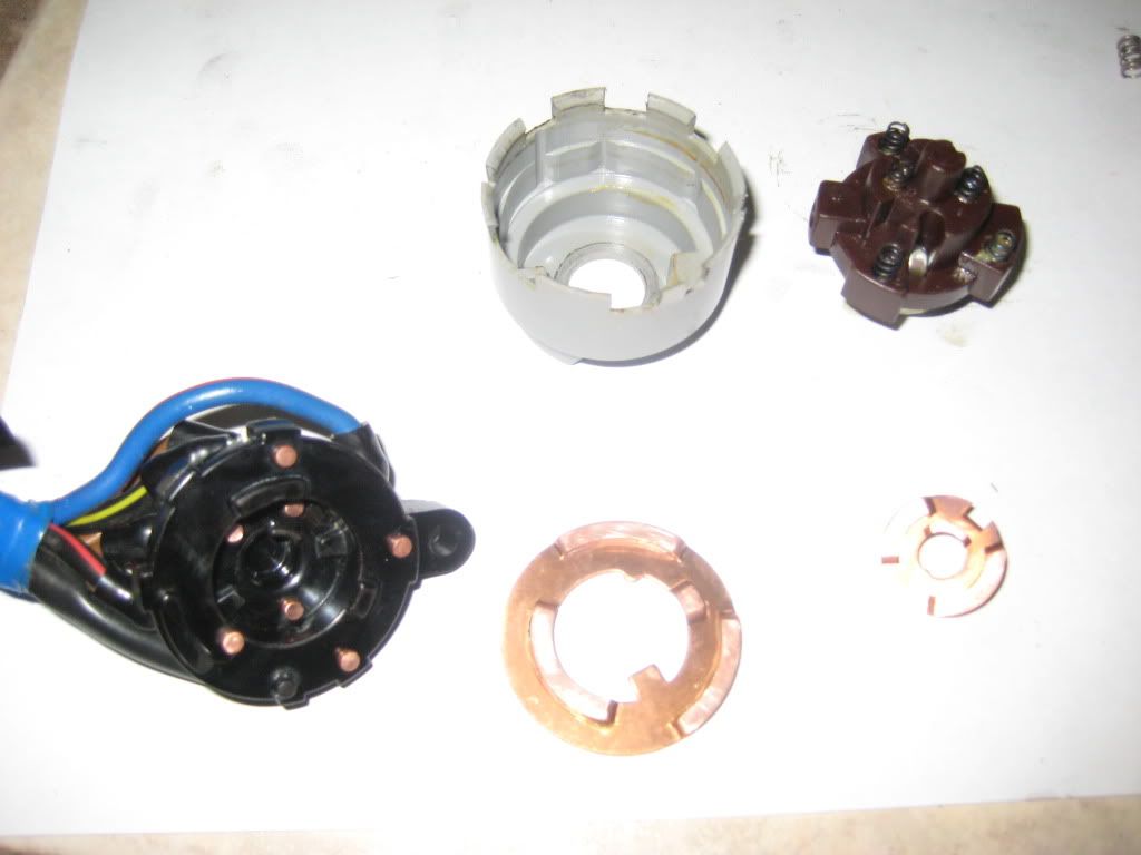
Now take your dielectric grease and apply it sparingly to the ring contacts and the stationary contacts in the areas shown:
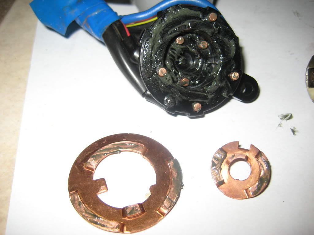
Next take your large copper ring and place in on the rotor assembly as pictured, the tang should fall into the larger gap.
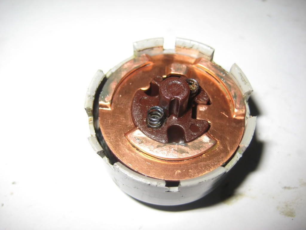
And the the small ring... Its indexed with a groove in the shaft.
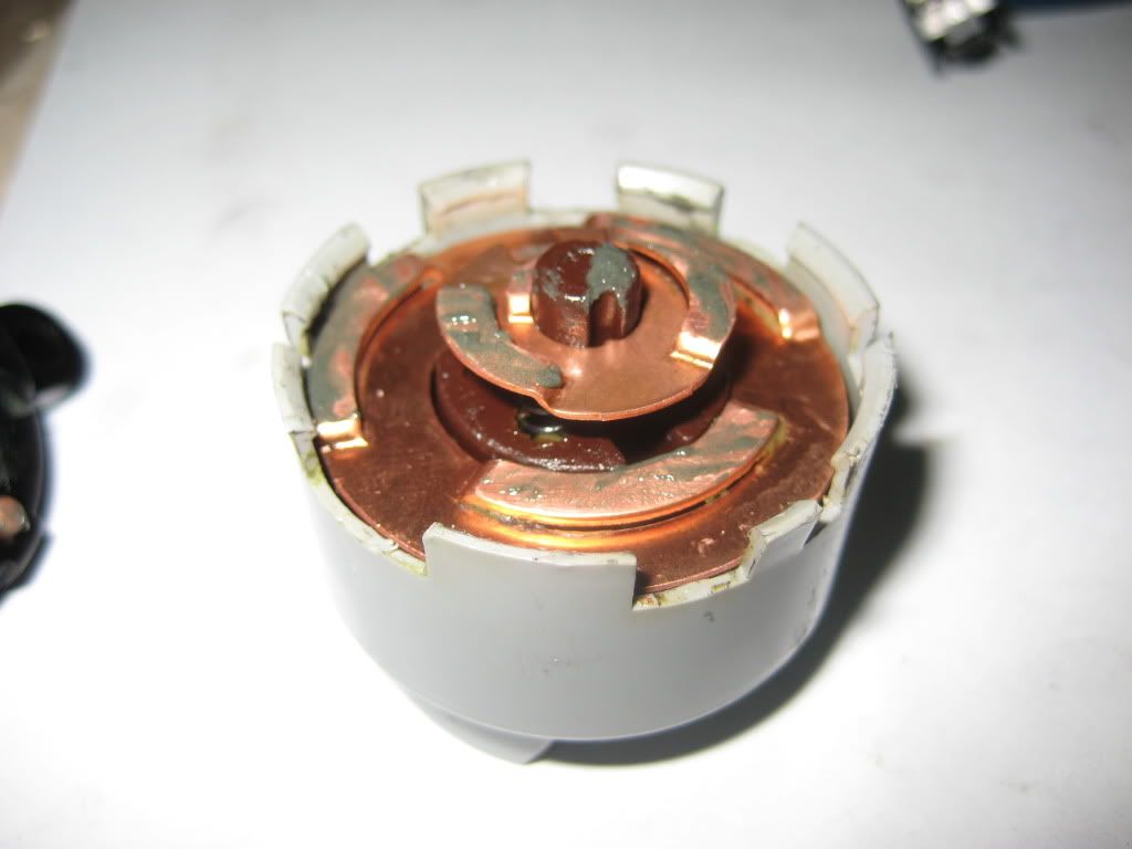
Next, rotate the rotor in the cover to the lock position (all the way counter clockwise) if its not already. Take the stationary part of the switch and align it with the assembled lower portion to get ready to snap it together. The part with the screw hole should line up with the largest notch out of the gray cover.
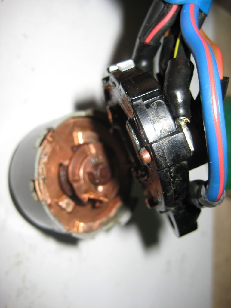
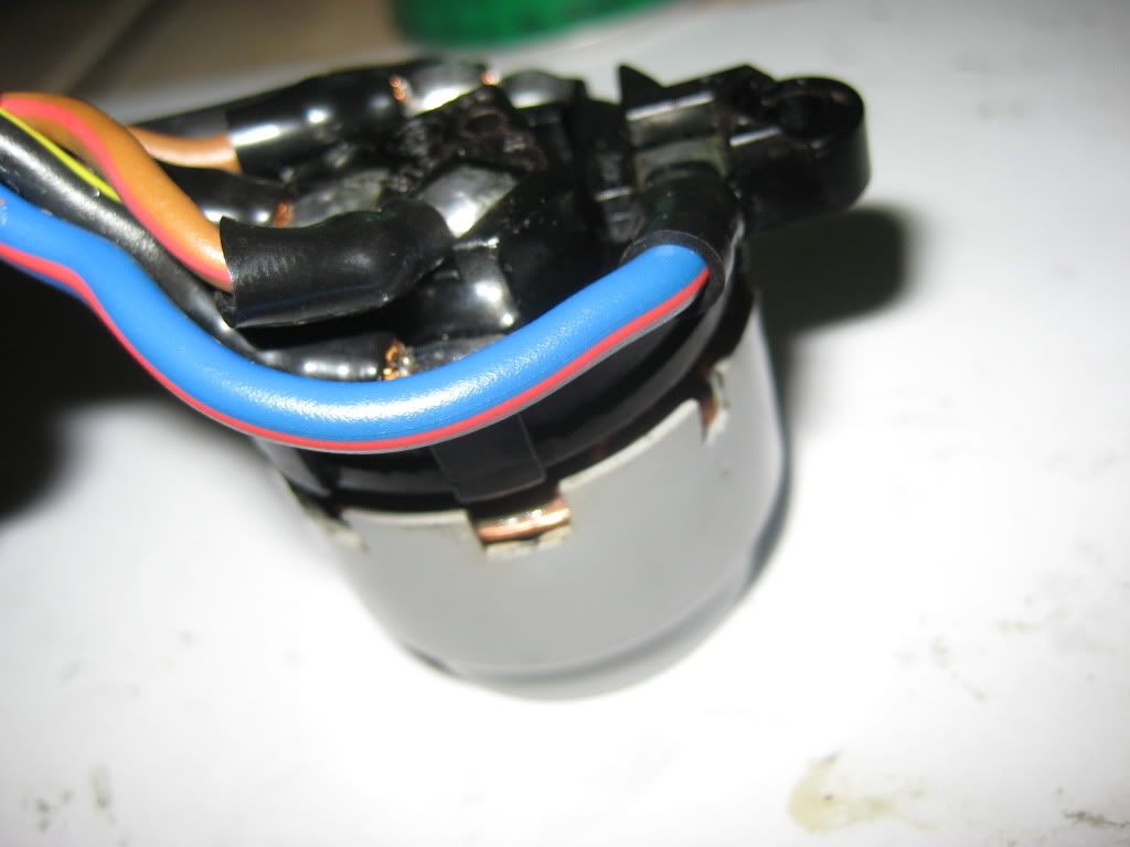
Carefully snap the two halves back together with slight pressure. If you have to push very hard, something is not lined up right. Take it apart, line it back up and try again. Once its together, use your screwdriver to check the rotation and the detent operation.
Note: This procedure was written for a 1990 Turbo Supra, not sure if the other years are the same or not.
Results:
After rebuilding my switch, reinstalling and testing it, I found that my voltage drop across the AM1 and IGN terminals of the switch when the engine is running is now .035 volts. Much better than the near 1 volt I was seeing before. I expect my starting issue will now be gone as this circuit also provides not only the current to the signal side of the starter relay, but also to the supply side of the starter relay and therefore also to the starter solenoid. This was resulting in less than necessary current getting to the starter solenoid to engage the starter.
Disclaimer:
Do this repair at your own risk. Messing it up could potentially be dangerous if ignition power was lost while driving the vehicle.
Here are the tools you will need:

Your ignition switch, a small flat blade screwdriver, a can of brake cleaner or other solvent, a few q-tips, some di-electric grease, and some 600 grit sandpaper.

Start by carefully prying the case of the switch open. Just pry all the way around a little at a time to get it free of the tangs, don't force anything since breaking it here will trash the whole thing.

Now once it starts to come apart keep the gray part facing downwards and try to keep the contents inside of that cover. Now Take the two brass contact rings out so it is left looking like this:

Now grab the two circular copper contact rings and clean all the old grease off. Check the rings for excessive wear, if the copper is worn too badly and is much thinner in the contact areas than the surrounding areas, the switch should be replaced.

Here is the culprit. That little circle that is worn into the ring was where the contact sat that fed power from AM1 circuit to the IGN circuit.


Next clean all the old dielectric grease from all surfaces of the contacts on the rings and the stationary contacts.

Next, get your 600 grit sandpaper, put it on a flat surface with the grit facing up. Place your larger ring on the sandpaper (raised contact side down, towards the grit) and sand the contacts evenly and a little at a time until you get an even finish all the way across. Only do enough to remove all the pitting and wear marks. Next, do the same thing to your small circular contact ring.


Next, take your screwdriver and wrap some sandpaper around the tip. Use this to take the pitting and oxidization out of the contact pins on the stationary part of the switch. Once again, just enough to get an even surface. You want to try and keep the sandpaper as flat as possible against the contact. When you are done, use the brakeclean to remove any copper filings on the parts and wipe clean.

(This part is optional) Now carefully push the rotor out of the cover while keeping your hand over the parts to (hopefully) catch the detent balls and springs as the two parts come apart. Clean out the old grease inside the cover where the detent balls ride and apply a small amount of new grease to those areas.

Put your two detent springs back into the holes in the sides of the rotor. Place a ball at the end of each one and squeeze them inward. Carefully insert the rotor into the cover while keeping the balls depressed. Make sure the return spring tangs go into the cover where the 180 degree relief is in the plastic.

Next look at the brown colored rotor part, and there will be 5 springs, one in each hole. Take the springs out and make sure all are still in good shape, and provide equal spring pressure, none are weak, etc. Place them back into their respective holes.

Now you should be left with all your contacts filed down and all parts clean and dry.

Now take your dielectric grease and apply it sparingly to the ring contacts and the stationary contacts in the areas shown:

Next take your large copper ring and place in on the rotor assembly as pictured, the tang should fall into the larger gap.

And the the small ring... Its indexed with a groove in the shaft.

Next, rotate the rotor in the cover to the lock position (all the way counter clockwise) if its not already. Take the stationary part of the switch and align it with the assembled lower portion to get ready to snap it together. The part with the screw hole should line up with the largest notch out of the gray cover.

Carefully snap the two halves back together with slight pressure. If you have to push very hard, something is not lined up right. Take it apart, line it back up and try again. Once its together, use your screwdriver to check the rotation and the detent operation.

Note: This procedure was written for a 1990 Turbo Supra, not sure if the other years are the same or not.
Results:
After rebuilding my switch, reinstalling and testing it, I found that my voltage drop across the AM1 and IGN terminals of the switch when the engine is running is now .035 volts. Much better than the near 1 volt I was seeing before. I expect my starting issue will now be gone as this circuit also provides not only the current to the signal side of the starter relay, but also to the supply side of the starter relay and therefore also to the starter solenoid. This was resulting in less than necessary current getting to the starter solenoid to engage the starter.
Disclaimer:
Do this repair at your own risk. Messing it up could potentially be dangerous if ignition power was lost while driving the vehicle.
