
Wiring in a stereo is usually a can of worms in my experience. If there's a stock system there then thank your lucky stars and get yourself an ISO converter for your new head unit. I always end up with at least one previous dodgy install and that was the case during this install. Unfortunately this prevented me from doing a nice neat guide but it'll probably give more practical info this way anyway.
Step 1 - Remove the surround for the stereo (See steps 14 through 21 in the turbo timer guide)
Step 2 - You now have access to the cradle around the stereo. Undo the four screws that hold it in place
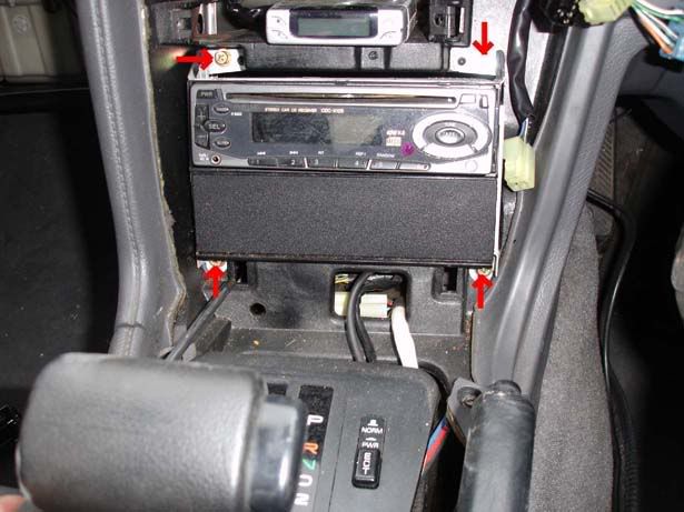
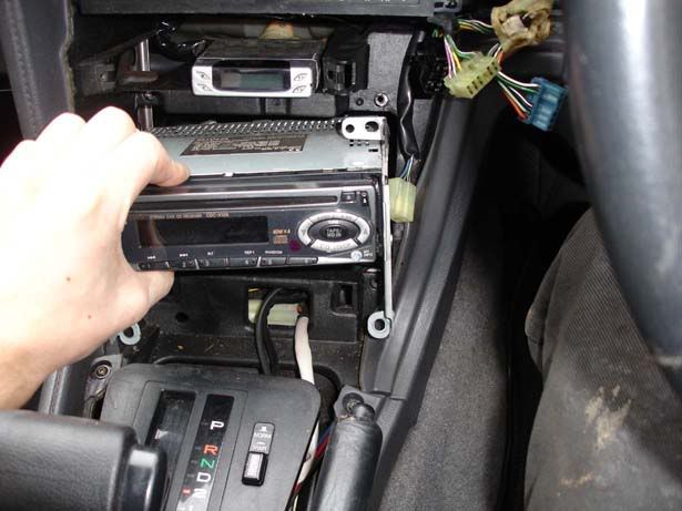
Step 3 - Slide the whole unit out forwards (Put your gear shift lever in an unobtrusive position)
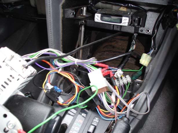
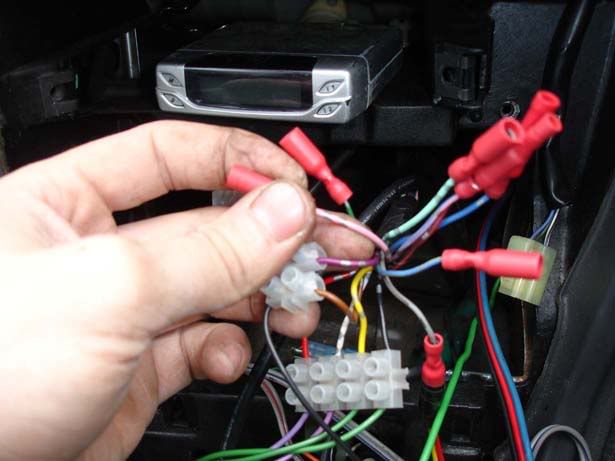
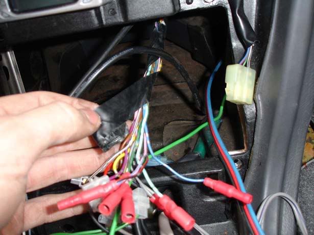
Step 4 - Admire the rats nest you have to deal with
Step 5 - This little bunch is the ISO wiring for speakers. You always have two purple, white, grey and green - one will be plain and one will have a black stripe down it. They usually have writing on to tell you which set of wires is for each speaker
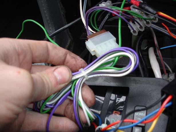
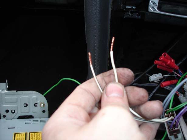
Step 6 - Pick a set of wires (any two the same colour so they will power a speaker) and strip the ends of the wires as shown
Step 7 - Grab a voltmeter (This is a tool you really need if working on stereos or you'll be in danger of popping fuses, wiring up incorrectly and generally screwing things up), put it on the setting shown for continuity. Basically we are going to find out which wires are connected to each other (via a speaker of course) in the stock wiring loom so we can hook them up to our ANSI wiring
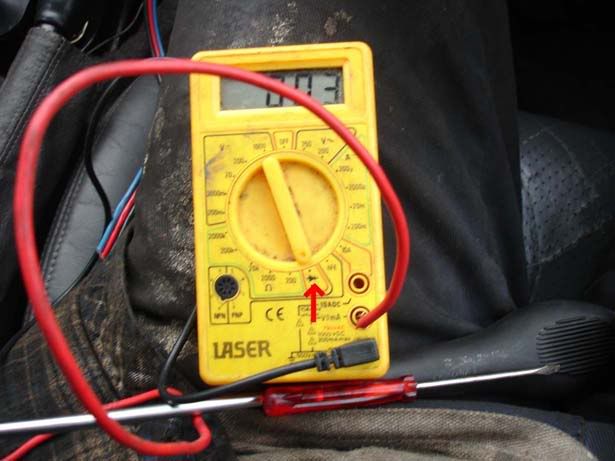
Step 8 - Put the probes of your voltmeter on one of the wires for the stereo and then probe all the others until you get a sign of continuity. You will see the voltmeter show a number close to zero when you have a match, otherwise it will be on something around 1
Note : Once you've found a match, check the wire isn't ground (You have quite a few grounds knocking about uynder there and it might not be a speaker you have found) by putting one probe on the wire and one on the chassis somewhere (There are loads of ground points around the stereo, most of the bolts will work around the gearstick).
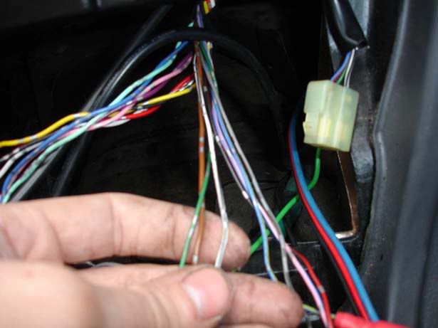
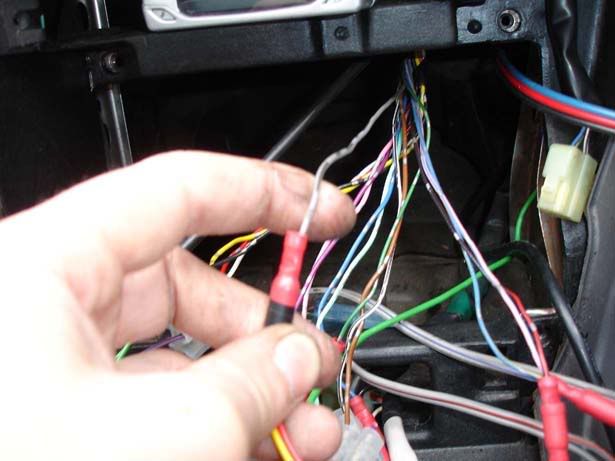
Assuming you don't get continuity then you have probably found a speaker (Picture shows my first pair of wires)
Step 9 - For mine I found that :
1. Pink + silver lines went with purple + silver lines to power the front left speaker (shown in previous step)
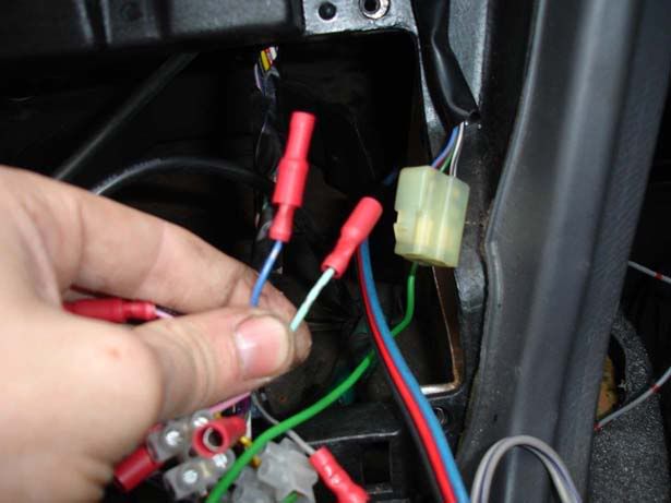
2. Blue with silver lines went with turquoise with silver lines to the front right (See picture)
3. Yellow with silver lines went with black with silver lines to the rear right
4. Red with silver lines went with white with silver lines to the rear left
Tape/mark/identify in some way which wires are for which speaker and then move on to step 10 before connecting anything up
Step 10 - Unwrap the insulation tape to give you a bit more flexibility with the wires
Step 11 - Find any of the remaining wires that go to ground. I found three, brown with silver lines, green with silver lines and with with a black stripe down it.
Step 12 - Find any live and switched live wires out of the remaining unknowns. A live wire will be on all the time (You need one of these to remember settings in the head unit such as radio stations etc). A 'switched live' will become live when you put the key in the accessory position and this usually turns the head unit on
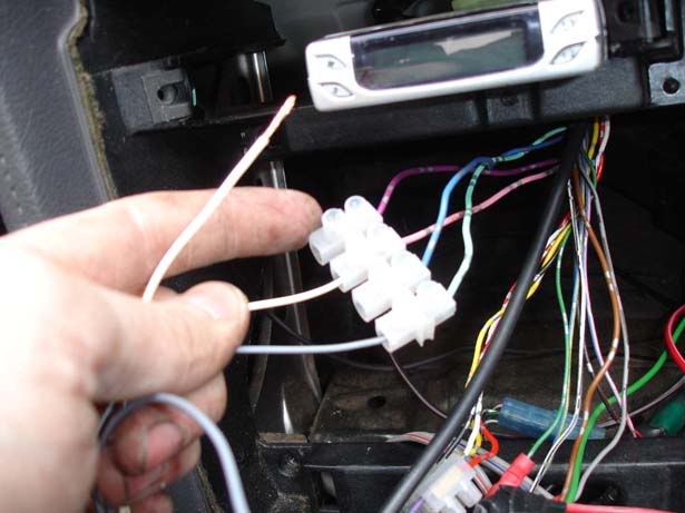
I only had one live wire and that was a switched live (grey with black lines as shown), this was being tied into the power and the memory for the stereo which meant every time the key was taken out, all settings were lost. This meant I had to hunt for a constant live wire and splice into that so I could have a permanent live feed for the stereo.
Step 13 - You now have all speaker wires identified, a switched live feed, hopefully you found a permanent live too and also one or more ground wires. You'll also have a couple spare no doubt. Time to start wiring them up - start wiuth the speaker wires. Handy tip is to wire both the stock wires into a terminal block and one of the ISO wires. Reason for this is that you get no noise out any speakers when you turn the head unit on which means you can touch each of the dangling ISO wires on in turn and make sure each speaker works properly.
Step 14 - Connect your permanent live feed to the yellow ISO wire. Connect at least one ground wire (I chose the brown one) to the black ISO wire. Finally, connect your switched live to the red ISO wire
Step 15 - At this point you should have a fully operational system. There is a blue wire which comes off the ISO connector which will allow you to power an amp or aftermarket electric aerial (It goes to 12 volts when the stereo is switched on). This can be ignored if you have the stock antenna because it is a bit more complicated (See the guide for installing an electric antenna)
Hopefully that'll give you an idea of what wires do what and how to use a voltmeter to help you out. Good luck!
Step 1 - Remove the surround for the stereo (See steps 14 through 21 in the turbo timer guide)
Step 2 - You now have access to the cradle around the stereo. Undo the four screws that hold it in place
Step 3 - Slide the whole unit out forwards (Put your gear shift lever in an unobtrusive position)
Step 4 - Admire the rats nest you have to deal with
Step 5 - This little bunch is the ISO wiring for speakers. You always have two purple, white, grey and green - one will be plain and one will have a black stripe down it. They usually have writing on to tell you which set of wires is for each speaker
Step 6 - Pick a set of wires (any two the same colour so they will power a speaker) and strip the ends of the wires as shown
Step 7 - Grab a voltmeter (This is a tool you really need if working on stereos or you'll be in danger of popping fuses, wiring up incorrectly and generally screwing things up), put it on the setting shown for continuity. Basically we are going to find out which wires are connected to each other (via a speaker of course) in the stock wiring loom so we can hook them up to our ANSI wiring
Step 8 - Put the probes of your voltmeter on one of the wires for the stereo and then probe all the others until you get a sign of continuity. You will see the voltmeter show a number close to zero when you have a match, otherwise it will be on something around 1
Note : Once you've found a match, check the wire isn't ground (You have quite a few grounds knocking about uynder there and it might not be a speaker you have found) by putting one probe on the wire and one on the chassis somewhere (There are loads of ground points around the stereo, most of the bolts will work around the gearstick).
Assuming you don't get continuity then you have probably found a speaker (Picture shows my first pair of wires)
Step 9 - For mine I found that :
1. Pink + silver lines went with purple + silver lines to power the front left speaker (shown in previous step)
2. Blue with silver lines went with turquoise with silver lines to the front right (See picture)
3. Yellow with silver lines went with black with silver lines to the rear right
4. Red with silver lines went with white with silver lines to the rear left
Tape/mark/identify in some way which wires are for which speaker and then move on to step 10 before connecting anything up
Step 10 - Unwrap the insulation tape to give you a bit more flexibility with the wires
Step 11 - Find any of the remaining wires that go to ground. I found three, brown with silver lines, green with silver lines and with with a black stripe down it.
Step 12 - Find any live and switched live wires out of the remaining unknowns. A live wire will be on all the time (You need one of these to remember settings in the head unit such as radio stations etc). A 'switched live' will become live when you put the key in the accessory position and this usually turns the head unit on
I only had one live wire and that was a switched live (grey with black lines as shown), this was being tied into the power and the memory for the stereo which meant every time the key was taken out, all settings were lost. This meant I had to hunt for a constant live wire and splice into that so I could have a permanent live feed for the stereo.
Step 13 - You now have all speaker wires identified, a switched live feed, hopefully you found a permanent live too and also one or more ground wires. You'll also have a couple spare no doubt. Time to start wiring them up - start wiuth the speaker wires. Handy tip is to wire both the stock wires into a terminal block and one of the ISO wires. Reason for this is that you get no noise out any speakers when you turn the head unit on which means you can touch each of the dangling ISO wires on in turn and make sure each speaker works properly.
Step 14 - Connect your permanent live feed to the yellow ISO wire. Connect at least one ground wire (I chose the brown one) to the black ISO wire. Finally, connect your switched live to the red ISO wire
Step 15 - At this point you should have a fully operational system. There is a blue wire which comes off the ISO connector which will allow you to power an amp or aftermarket electric aerial (It goes to 12 volts when the stereo is switched on). This can be ignored if you have the stock antenna because it is a bit more complicated (See the guide for installing an electric antenna)
Hopefully that'll give you an idea of what wires do what and how to use a voltmeter to help you out. Good luck!