GUIDE : Stripping a cylinder head

JSeaman

SM Official Expert: Guide Author
SM Expert
May 26, 2009
216
0
0
Derbyshire, UK
The engine removal guide will tell you how to get your 7M out the car and then this guide will tell you what to do with the engine when it's out. The only missing section is where I had to strip off all the ancillaries quite quickly to get the engine in my boot. Basically all the manifolds, brackets etc were very quickly stripped off leaving a bare engine ready for stripdown.

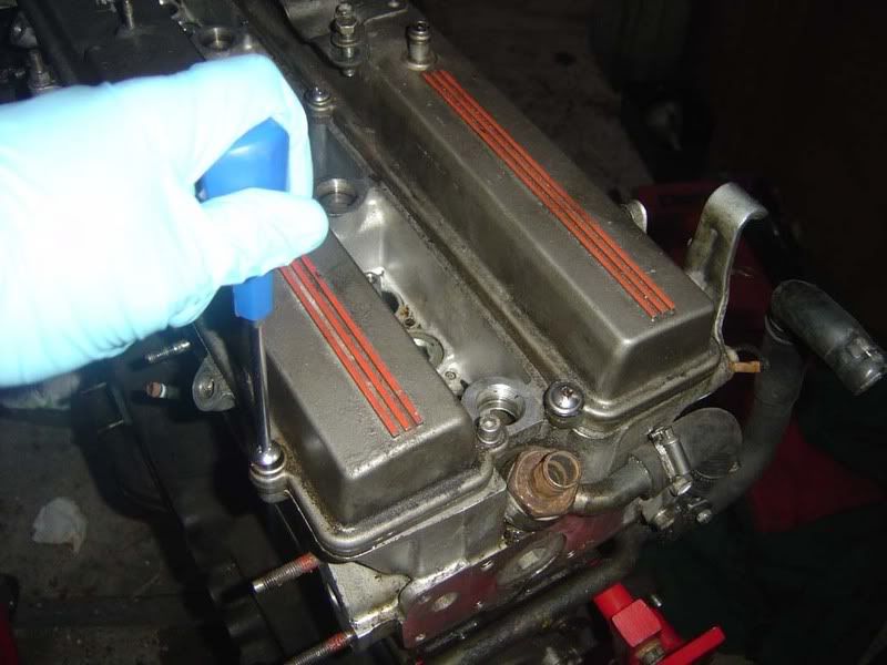
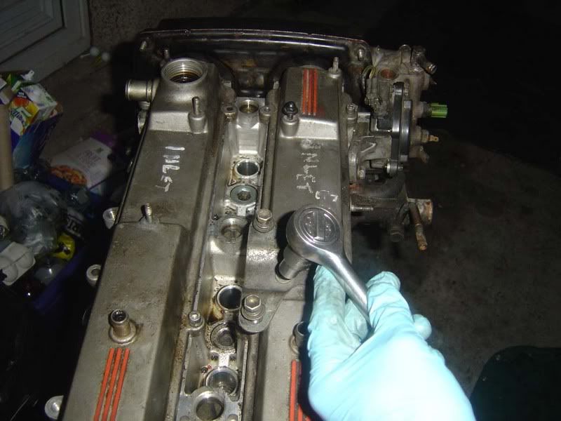
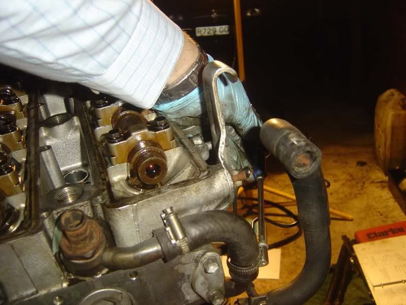
Step 1 - We'll start by removing the cam covers. There's a guide that covers removal of everything to get to the cam covers which might come in handy. If your car is anything like mine then you'll have the stock Toyota screws, random 10mm bolts and allen keys thrown in here!

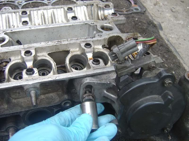
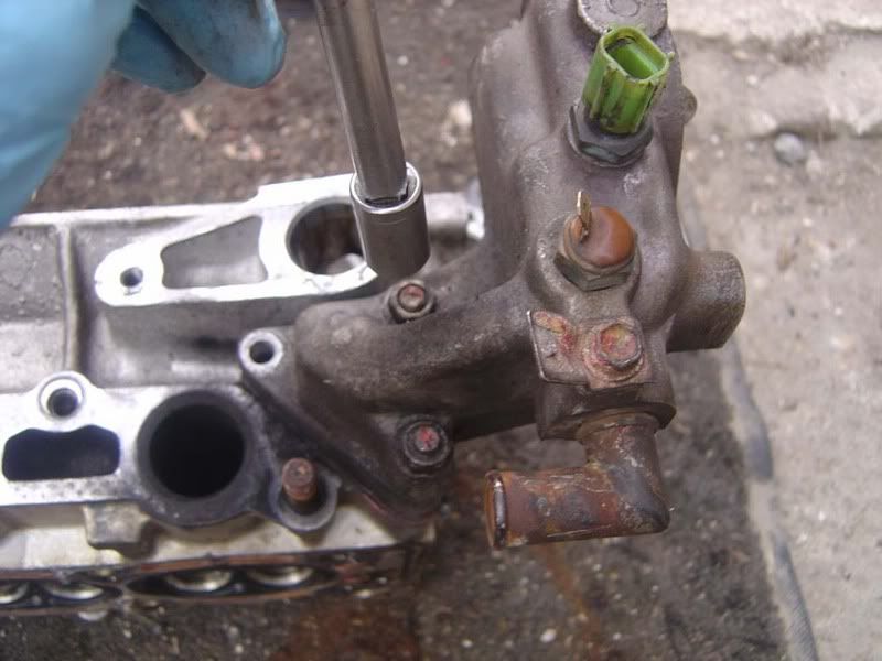
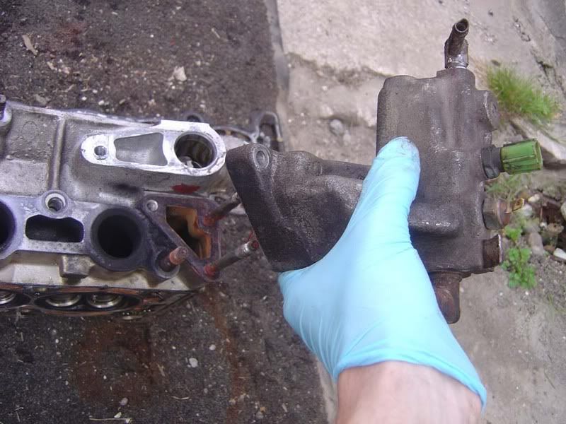
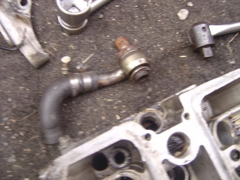
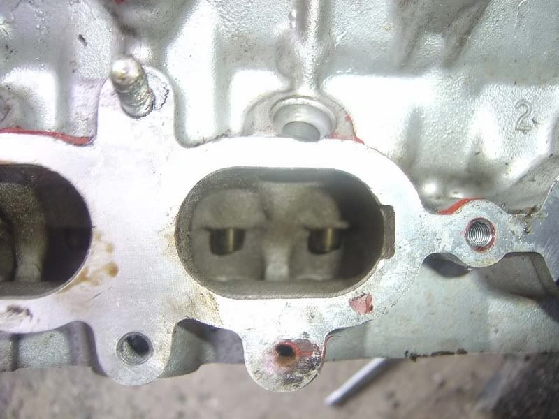
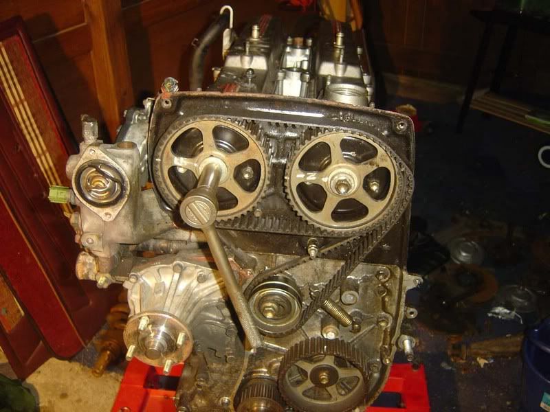
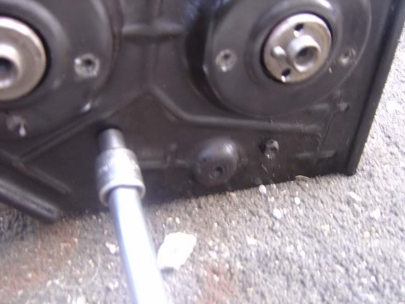
Note you will have to remove the bracket to support the 3000 pipe (as shown in picture 4) to get the final bolt out on the exhaust side)

p1329395_1.jpg

p1329395_2.jpg

p1329395_3.jpg

p1329395_4.jpg


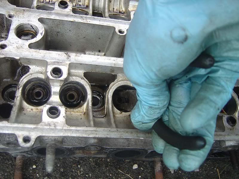
Step 2 - Tilt the cam covers to the side to free from the gasket

p1329395_5.jpg


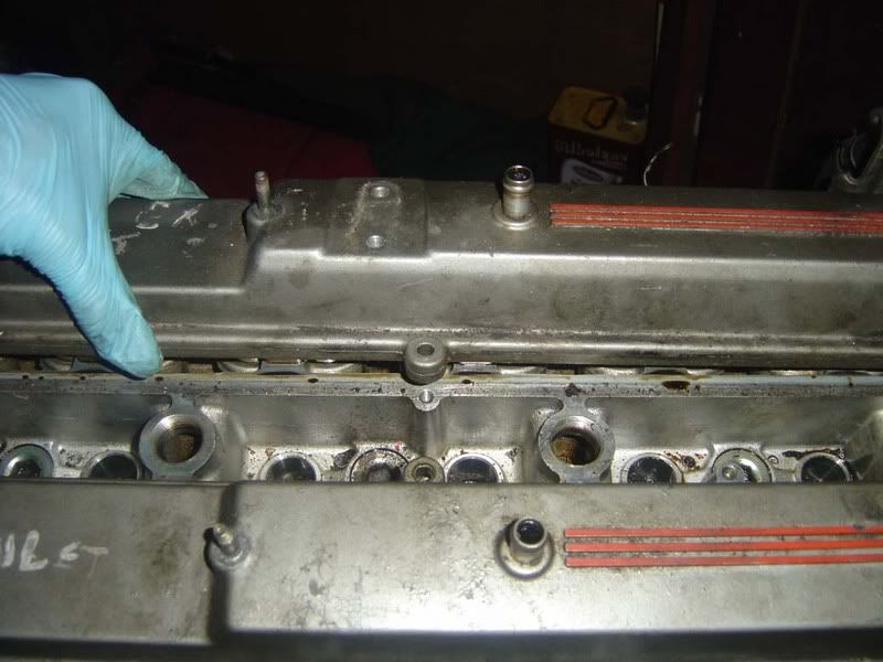
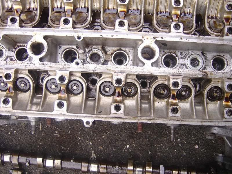
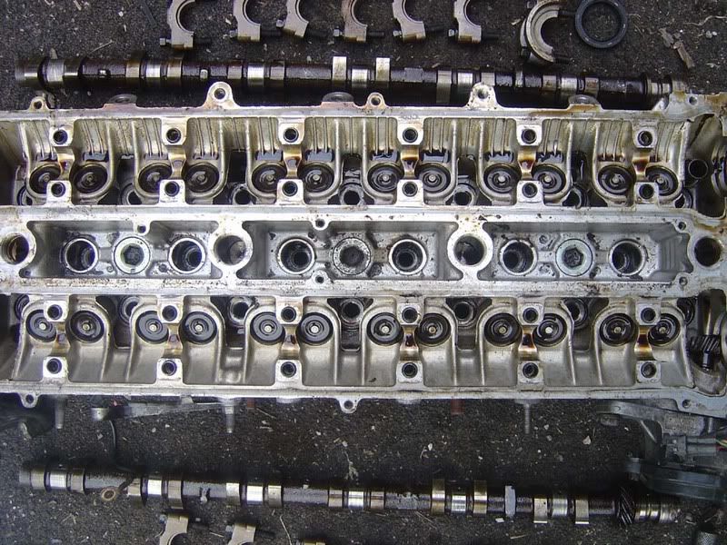
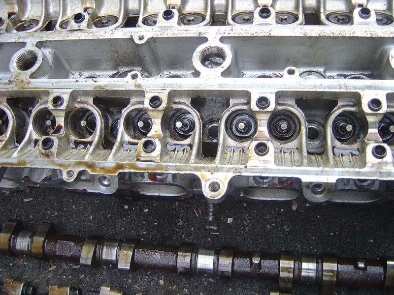
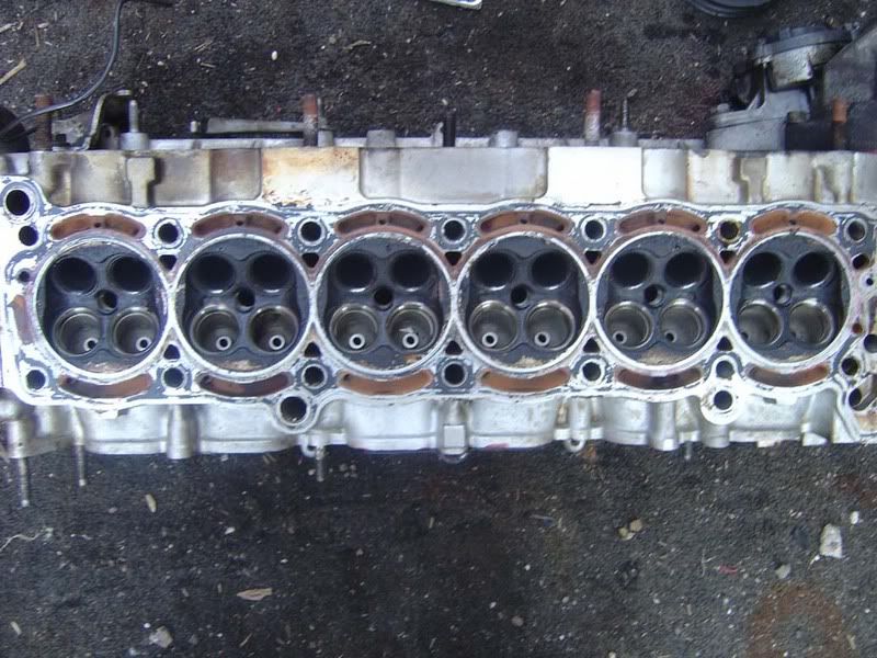
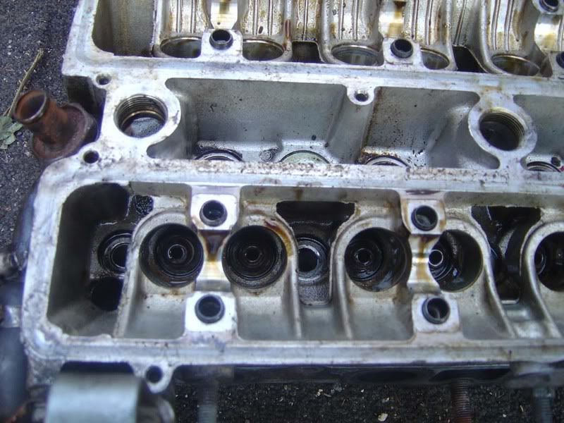
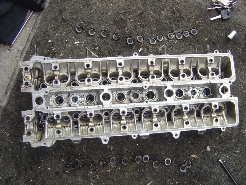
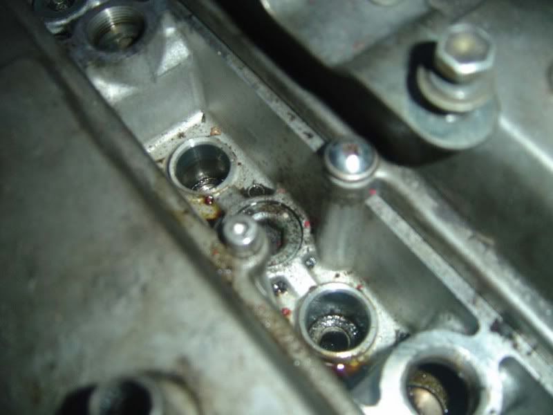
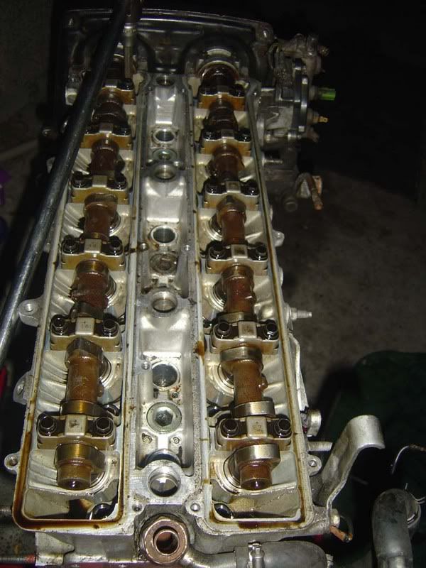
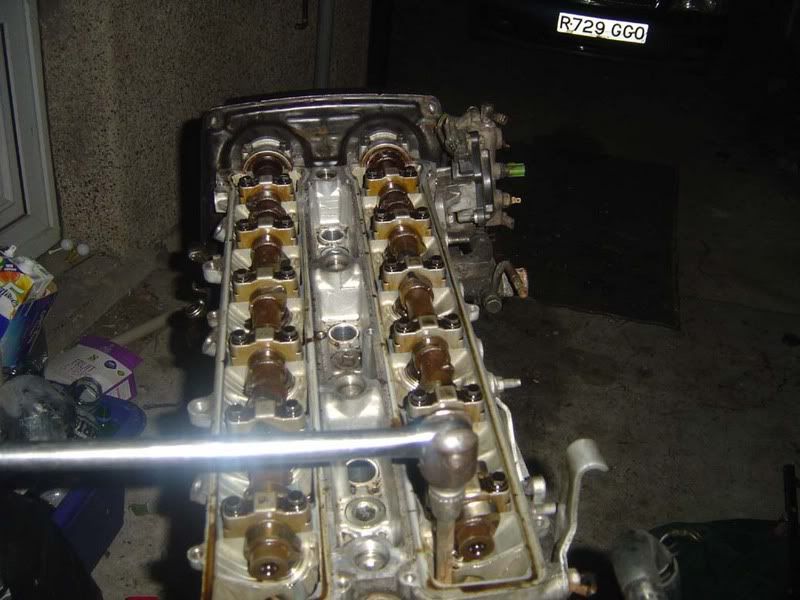
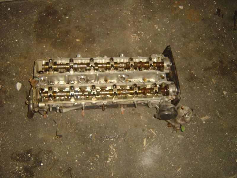
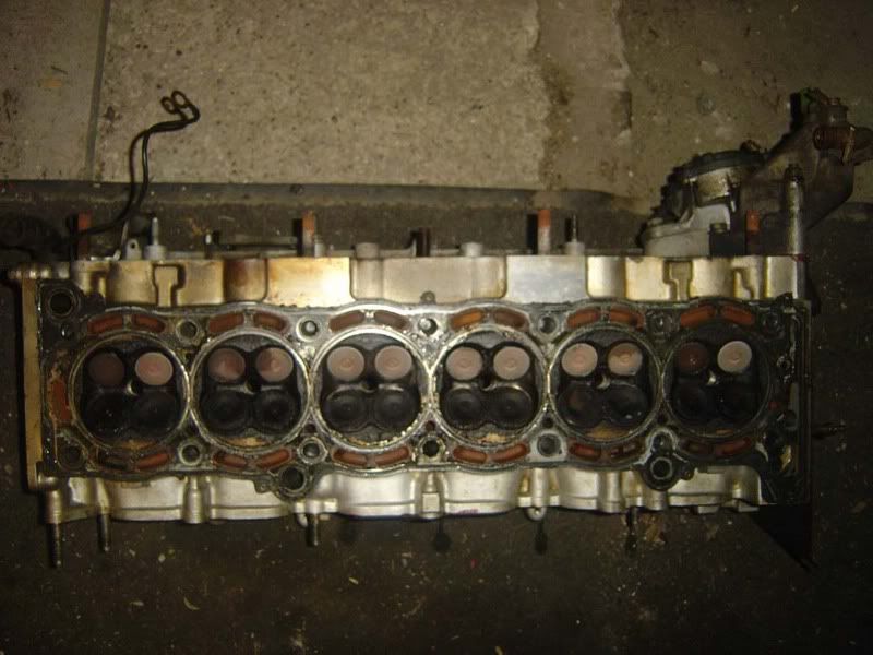
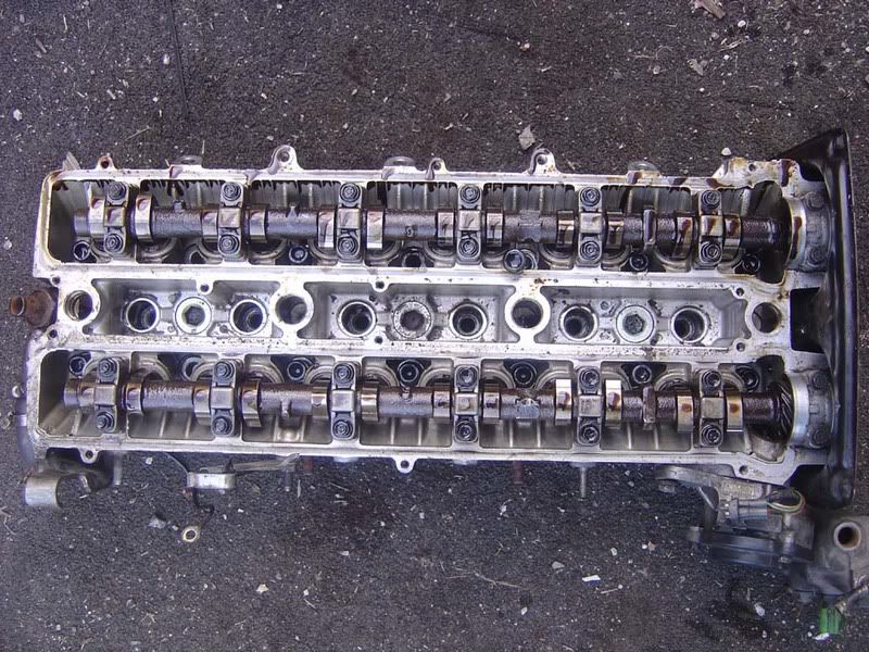
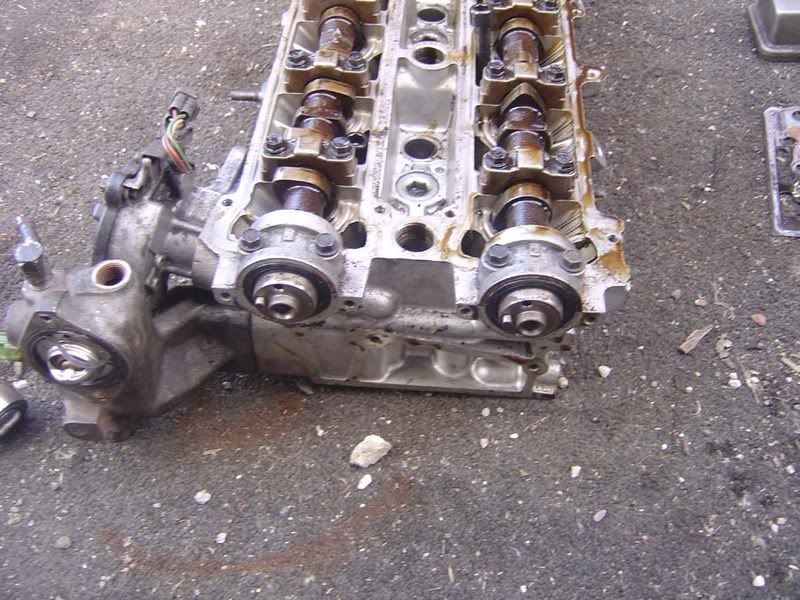
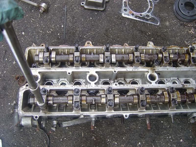
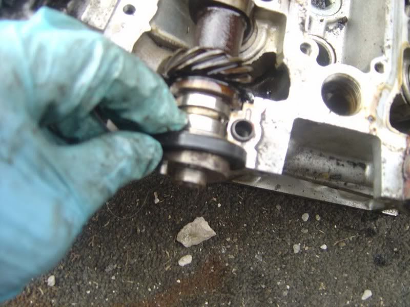
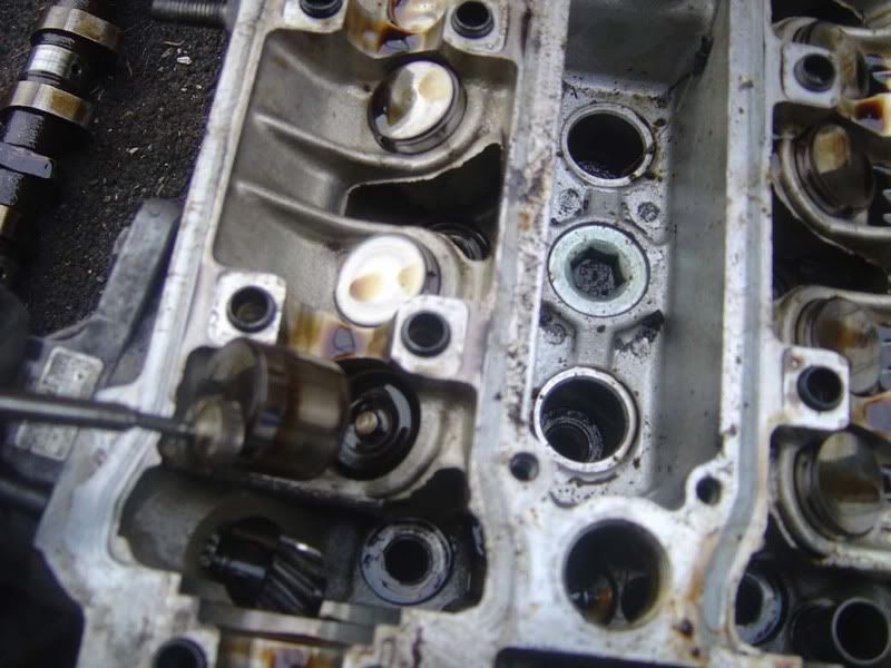
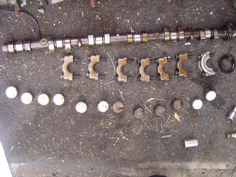
Step 3 - Now remove each cover to reveal the camshafts

p1329395_6.jpg


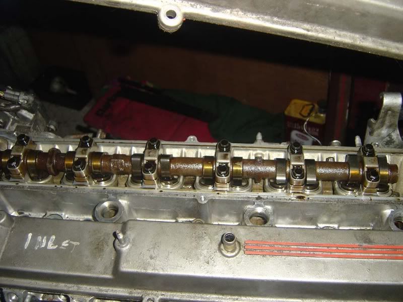
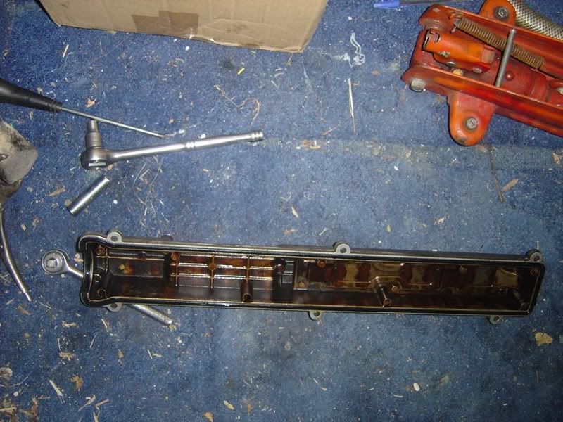
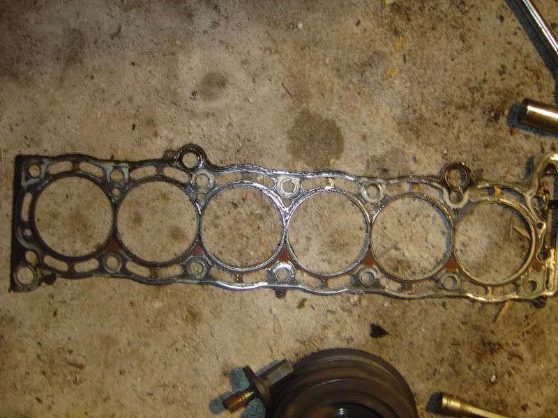
Step 4 - As with anything you remove, clean it up thoroughly then fit a new gasket when you put it back on. A toyota head gasket set will have most of what you need in it for about £80

p1329395_7.jpg


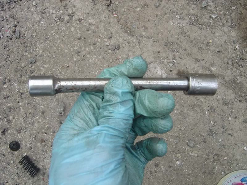
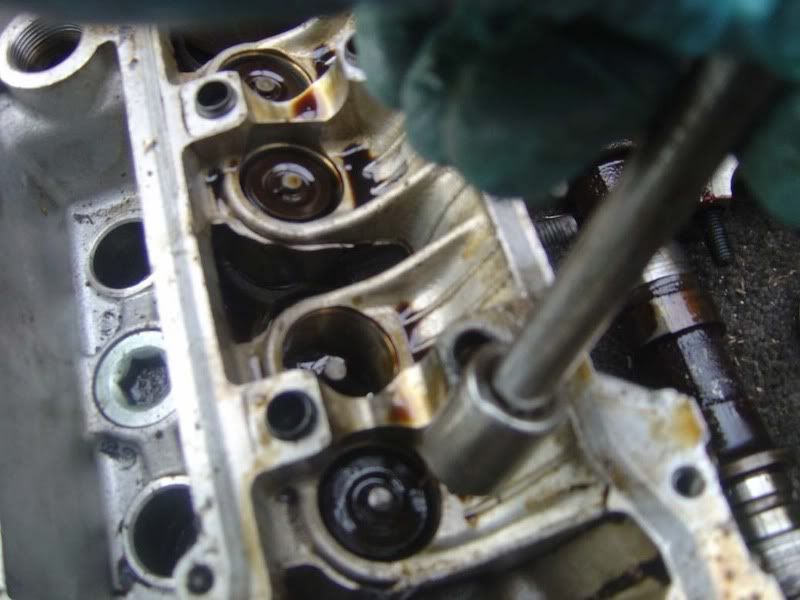
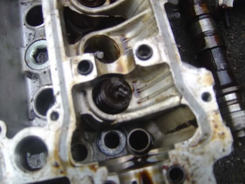
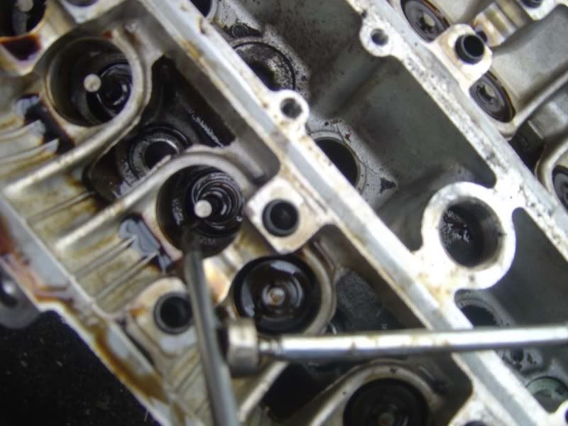
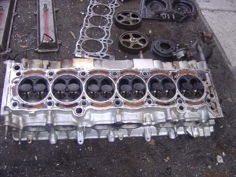
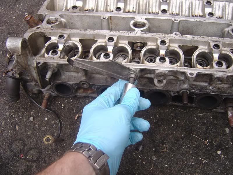
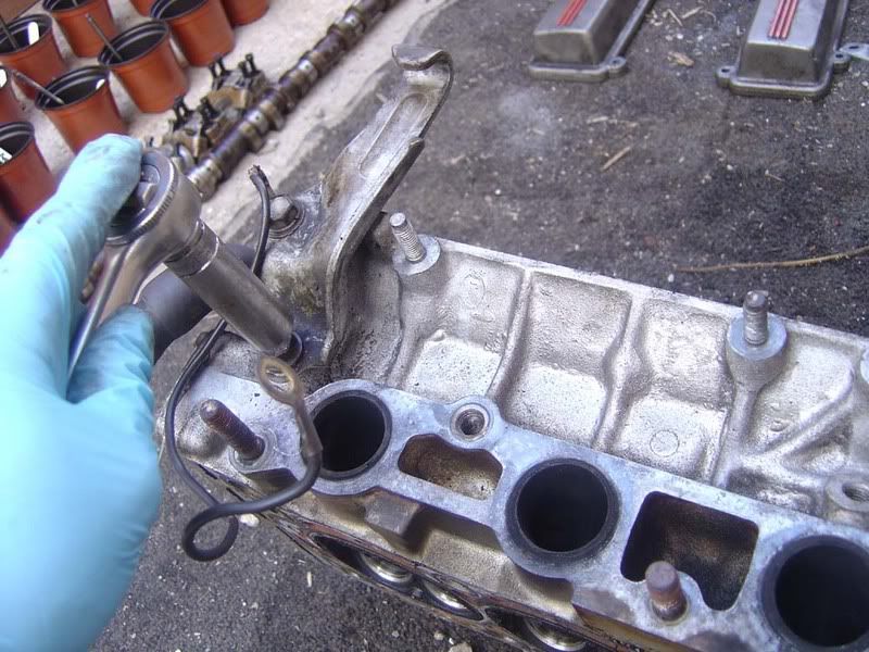
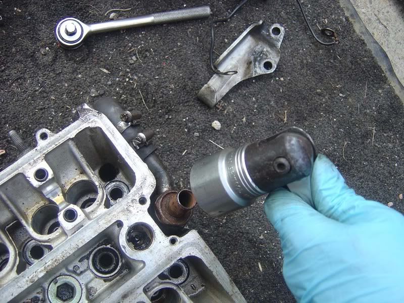
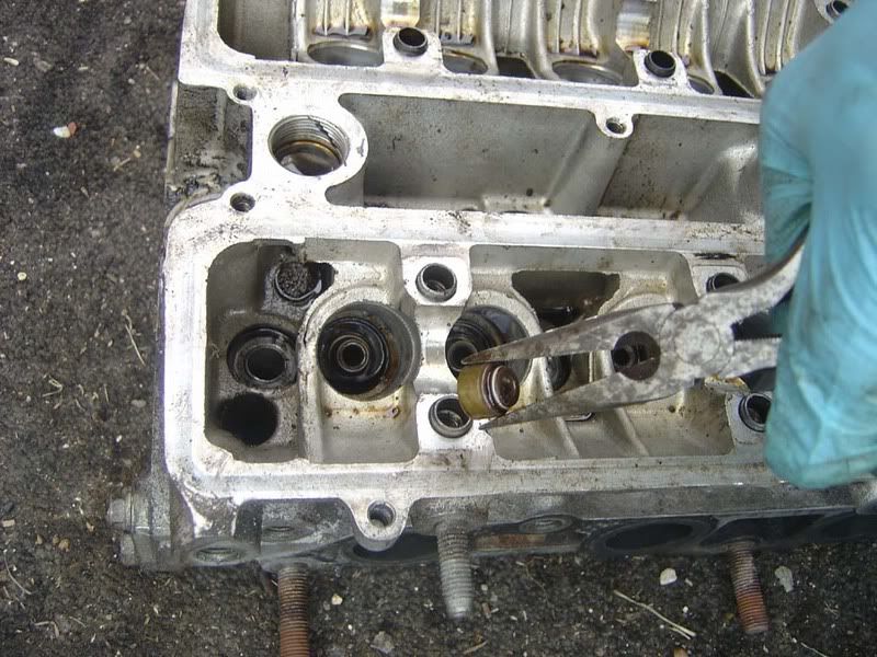
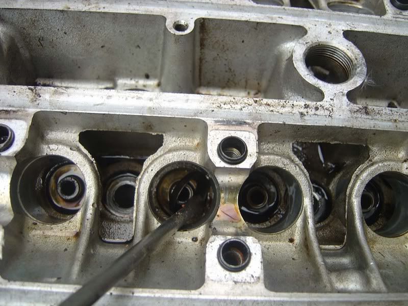
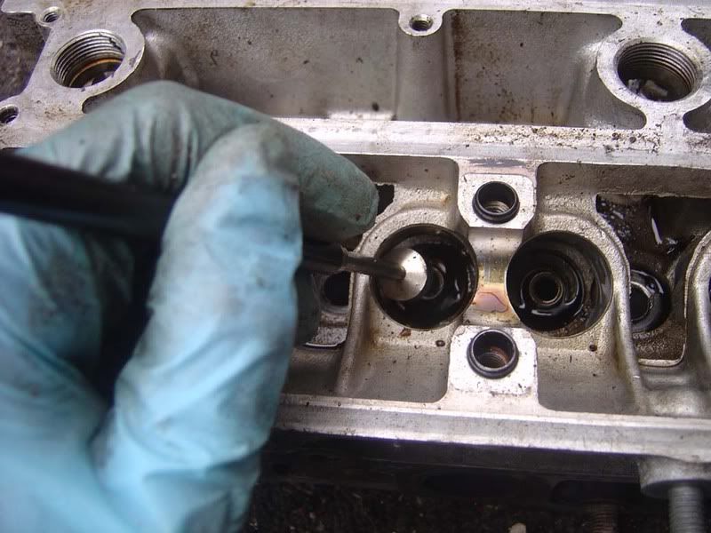
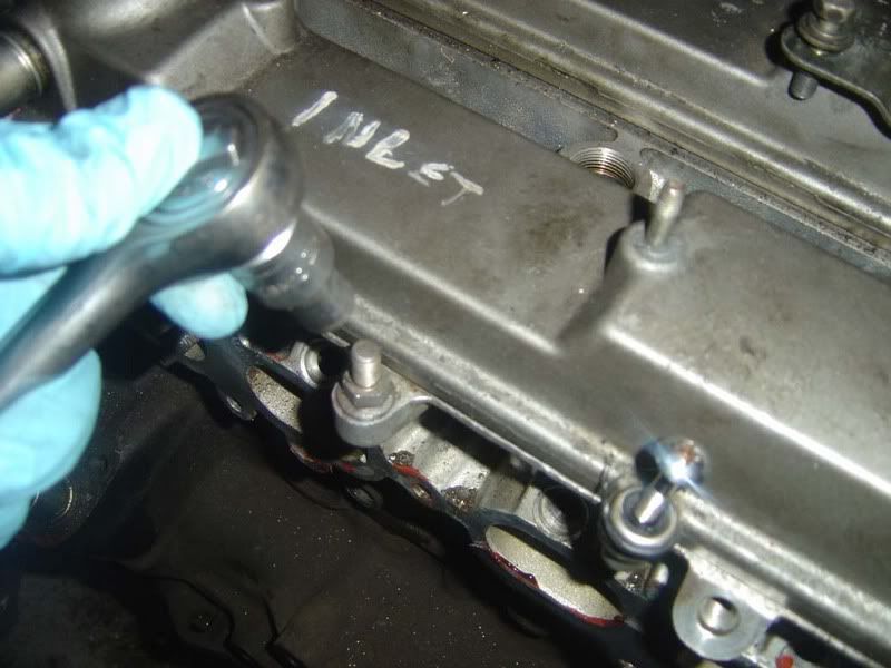
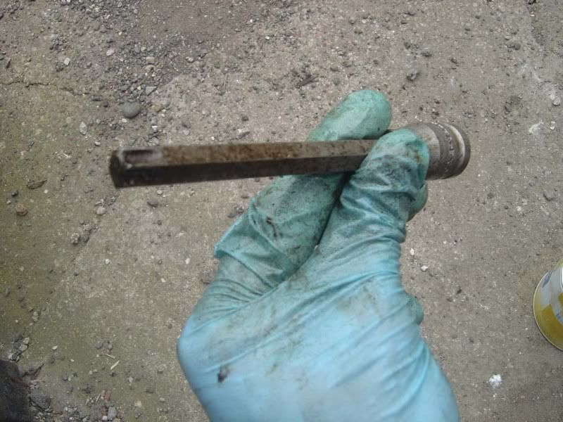
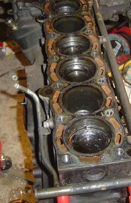
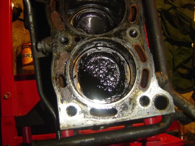
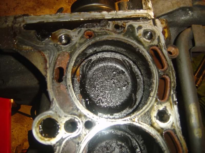
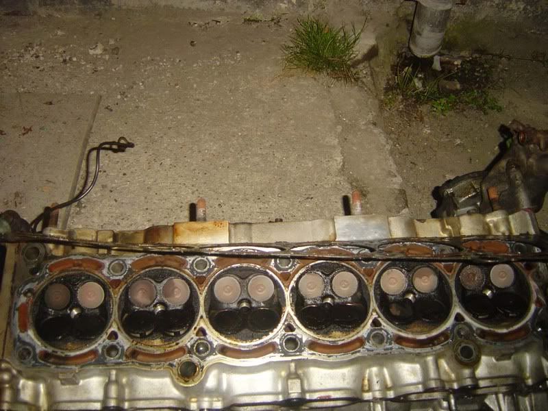
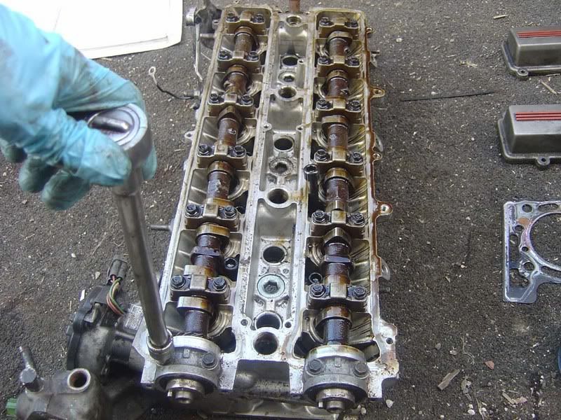
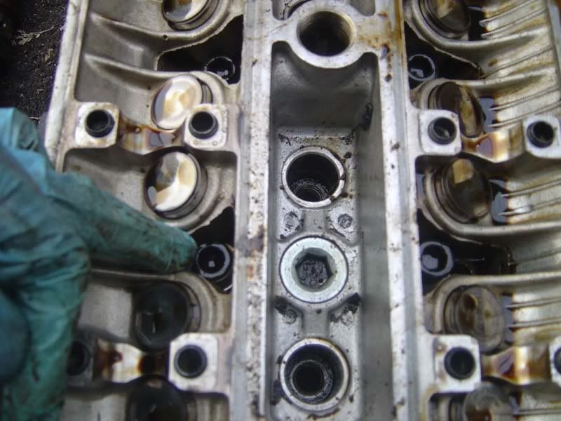
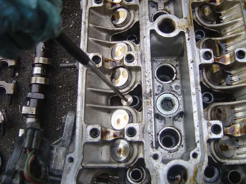
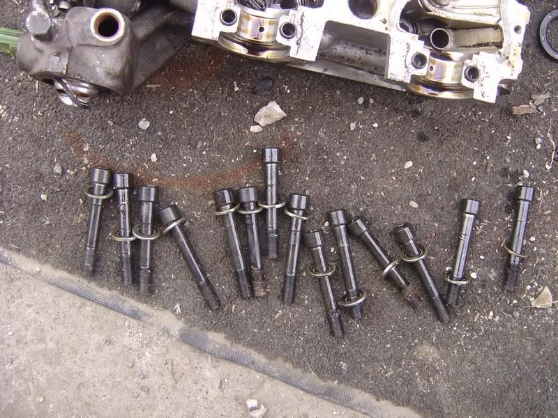
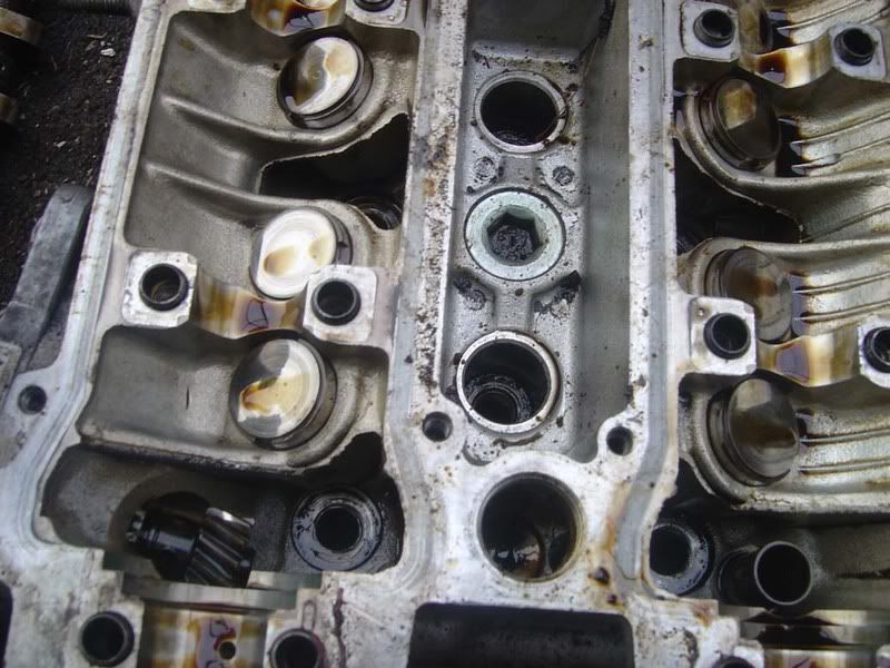
Step 5 - Cylinder head bolts are next. The head bolts are torqued quite high (not high enough from Toyota but that's a different story!), so will need a fair amount of force to shift. You should invest in either a long 10mm allen key socket or just hacksaw the small end off an allen key and fit that to a standard 10mm socket. Use a breaker bar to get the leverage you need and try to use a fluid motion rather than shocking the bolts by hitting the bar with a hammer. I always remove the head bolts in several stages:

1. 'Crack off' the bolts by which I mean move them about 1/8th - 1/4 of a turn
2. Turn each bolt a further 1/2 - 1 turn
3. Remove the bolts

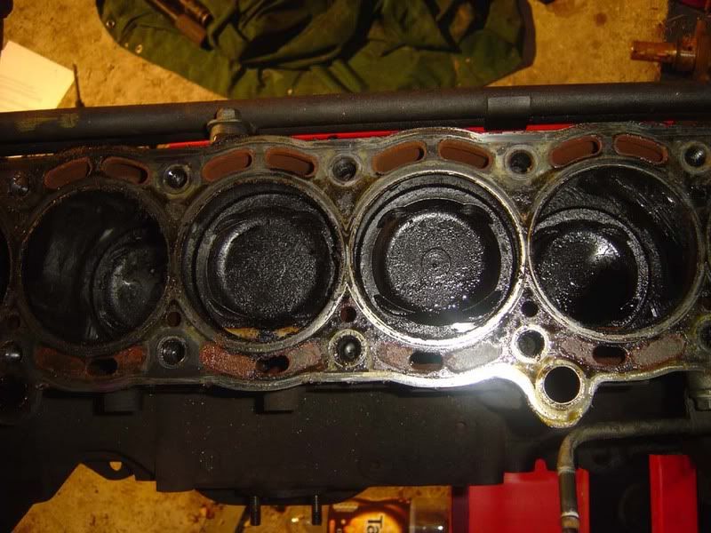
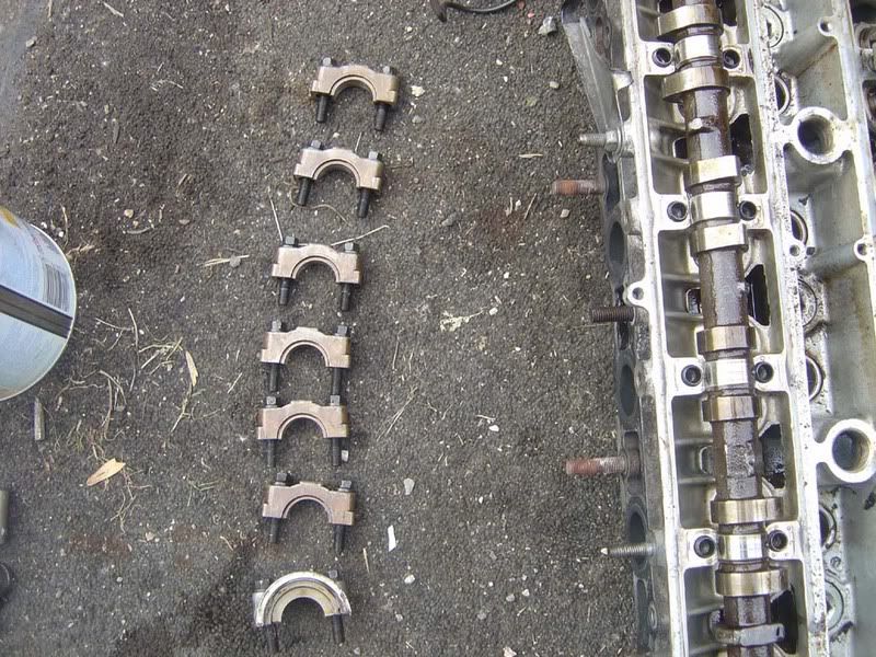
This is always done in the sequence shown below -

INLET

BACK 4 8 12 14 9 5 1 FRONT
BACK 2 6 10 13 11 7 3 FRONT

EXHAUST

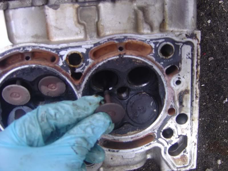
It's very important you use the correct sequence to minimise stress to the cylinder head. The head should be treated carefully as it is soft (aluminium) and can easily be stressed/damaged.

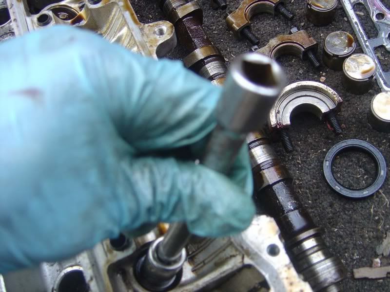
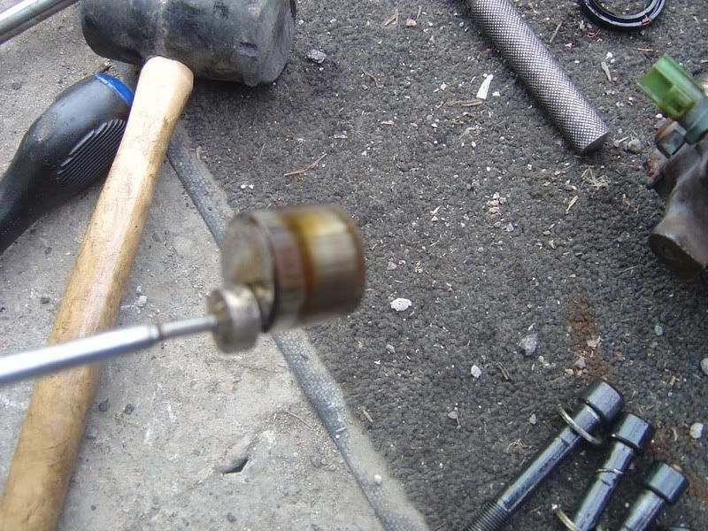
The third picture shows a 10mm torx style extension bar which will do the trick if you can't get an allen key one

p1329395_8.jpg

p1329395_9.jpg

p1329395_10.jpg


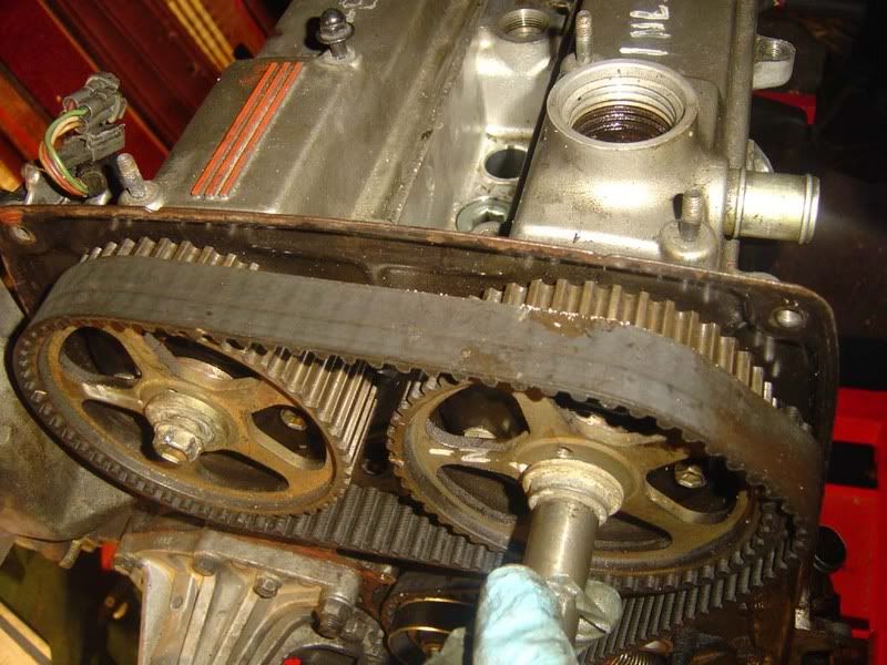
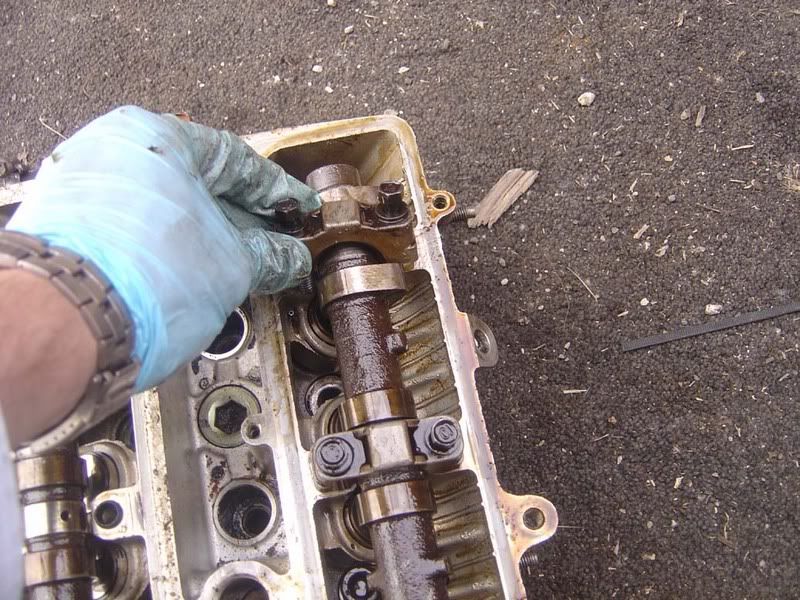
Step 6 - Follow the cam belt removal guide until step 17 i.e. all the stripdown stuff but none of the rebuild

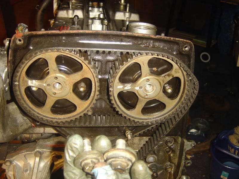
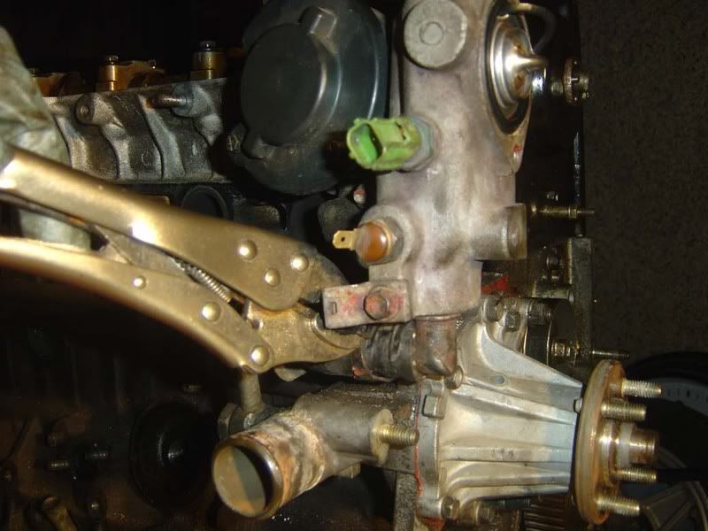
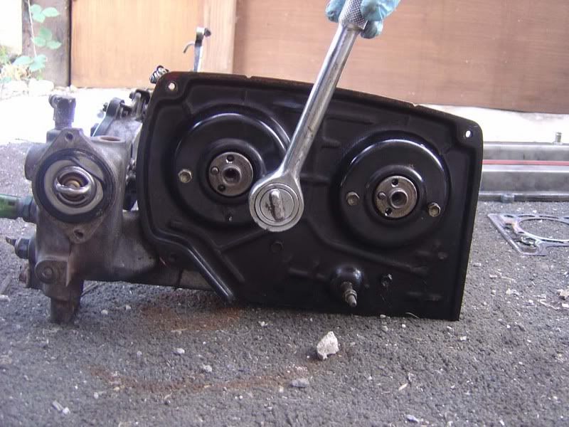
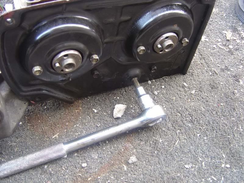
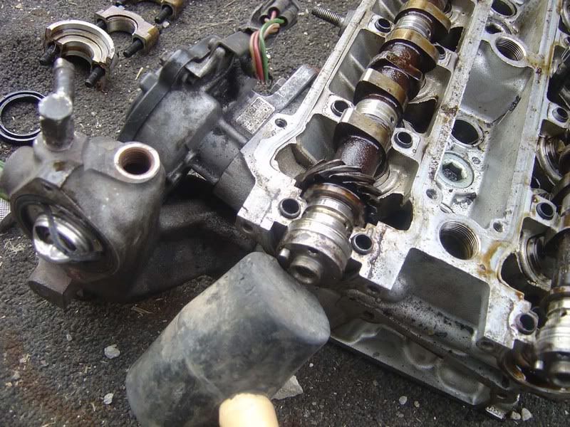
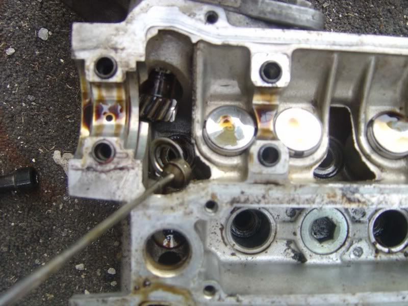
Step 7 - You need to lock the cam pulleys now which can be done with special service tools from Toyota (SSTs) or by fabricating your own. I just re-used the old cam belt I was going to throw away by wrapping it over both cam pulleys and the belt's idler pulley. This locked the wheels so I could crack off the 14mm centre nut

p1329395_11.jpg


Step 8 - The nuts should be easy to undo once they've been cracked off so you can now remove them by hand.

p1329395_12.jpg

p1329395_13.jpg

p1329395_14.jpg


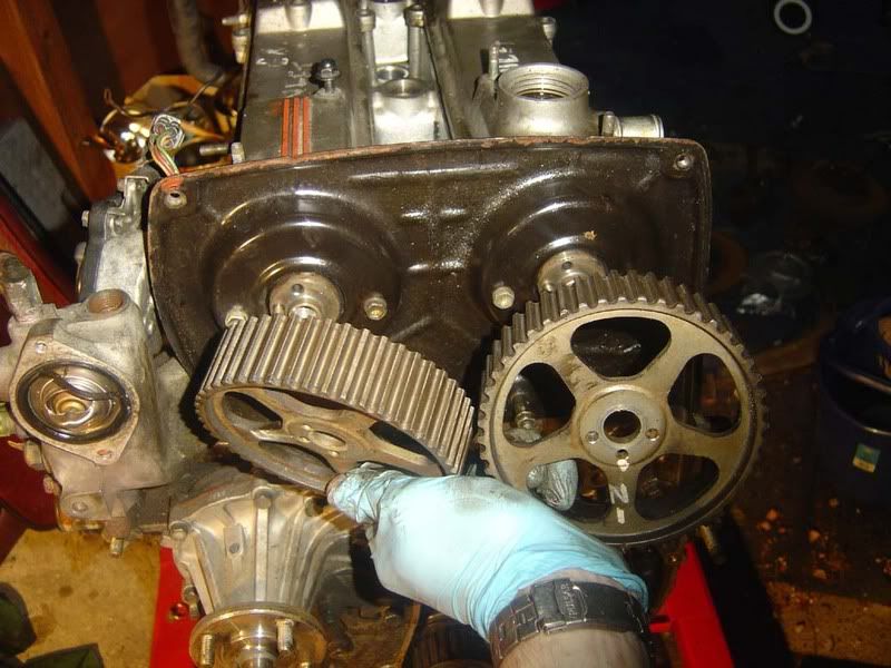
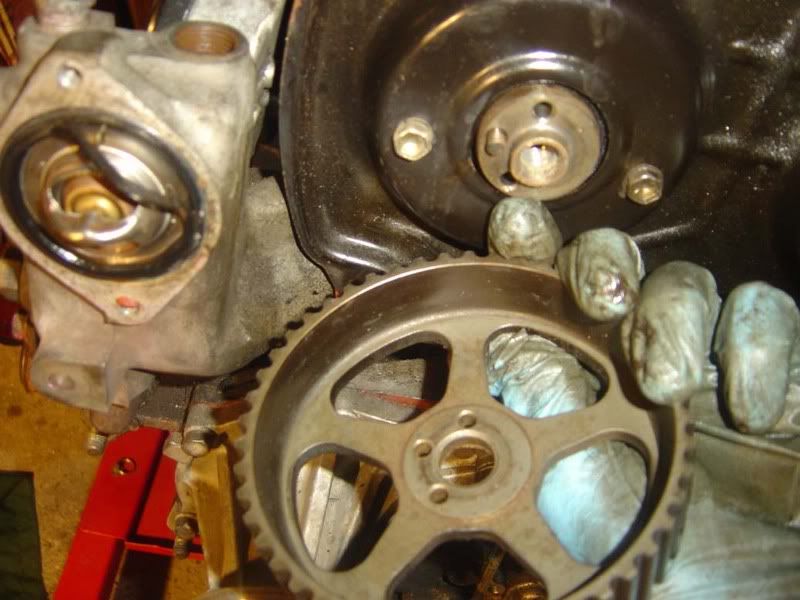
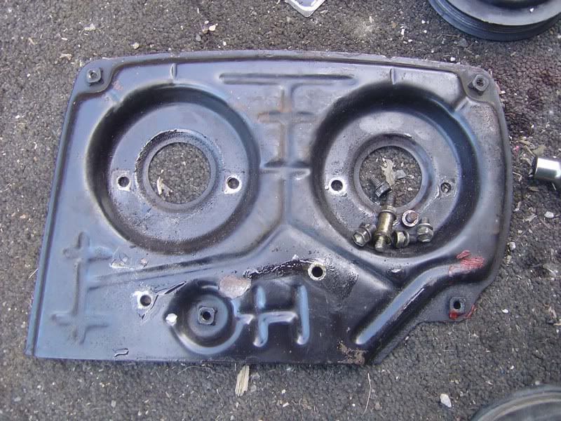
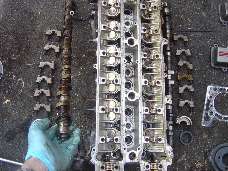
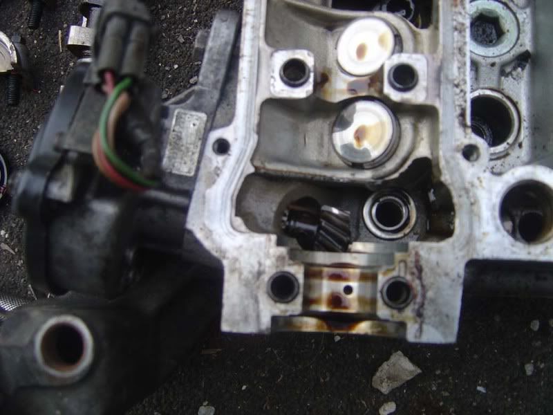
Step 9 - When you have removed the pulleys you will see there is a dowel in the camshaft that aligns with the centre of 3 holes in the pulley itself, you'll need this on refitting. Both pulleys are identical

p1329395_15.jpg
 

JSeaman

SM Official Expert: Guide Author
SM Expert
May 26, 2009
216
0
0
Derbyshire, UK
Step 10 - You are now approaching the time to separate the head and block so go round checking for anything linking the two together. I had two hoses to remove as shown below

p1329396_1.jpg

p1329396_2.jpg


Step 11 - The head isn't too heavy really but if you've got a second person then it would probably be easier. Try and lift it from the block as cleanly as possible, you don't want to be dropping it or damaging the surfaces at all. Remove it from the head and place it on some wooden blocks/carpet/anything that won't damage the face of the head

p1329396_3.jpg


Step 12 - Have a quick look around the block before you set to work on the head

p1329396_4.jpg

p1329396_5.jpg

p1329396_6.jpg

p1329396_7.jpg


Step 13 - Spin the head over and have a quick look at the valves. In my case the head gasket was stuck to the head so I removed it at this stage

p1329396_8.jpg

p1329396_9.jpg


Step 14 - Assuming you've stripped the engine for a head gasket (how presumptuous of me!) check the gasket, head and block surfaces for signs of leakage around the oil/coolant/cylinder paths. Identifying the problem area may also help to route out the cause as well as pointing out any potential damage caused.

If you're stripping down for a standard rebuild then just check everything is in spec (This guide will show you what to check). If you're stripping down for big ends then pay particular attention to the clearances and condition of the rods/crank. If you're doing a head gasket then look for signs such as one clean cylinder, oil in water etc. Whatever the reason for the stripdown you should check everything in this guide (and the block stripdown guide if appropriate) and also look for any potential problems that may have caused your stripdown.

p1329396_10.jpg


Step 15 - Flip the head so it's the right way up again and you can get access to the camshafts

p1329396_11.jpg


Step 16 - Time to remove the number 2 timing cover now, it's just a bunch of 10mm nuts

p1329396_12.jpg

p1329396_13.jpg

p1329396_14.jpg

p1329396_15.jpg
 

JSeaman

SM Official Expert: Guide Author
SM Expert
May 26, 2009
216
0
0
Derbyshire, UK
Step 17 - With the cover removed you will see that the cylinder head is actually pretty small and not too difficult to work on

p1329399_1.jpg


Step 18 - We start stripping the head itself by removing the camshaft caps. The shafts can break if you cut corners here so make sure you undo the bolts in several passes again like the head bolts and also in the torque pattern shown below:

BACK 6 3 5 4 7 2 1 FRONT

The final pass can easily be done by hand although the caps will be quite tight at first so a breaker bar might be useful

p1329399_2.jpg

p1329399_3.jpg


Step 19 - Now start removing the caps, to do this you should rock them backwards to crack off the seal then they will come out easily

p1329399_4.jpg


Step 20 - Order is important with the head, you need to clearly separate parts from around the head. You can't swap the order of the caps around. Thankfully they are marked from the front (1) to the back (7) for both inlet ('I') and exhaust ('E') but keep them in order anyway to avoid mistakes.

p1329399_5.jpg


Step 21 - Remove the oil seal at the front of each cam shaft, this will simply slide off towards the front of the head

p1329399_6.jpg


Step 22 - You can now remove the cam shafts, if they are really stubborn then a tap with a rubber mallet will free them

p1329399_7.jpg


Step 23 - Once you have done both sides you will be faced with a bunch of shiny silver circles, these are the valve 'shims' which are discs to adjust the clearance between the lobe (pointy bit) of the cam and the valve lifters.

p1329399_8.jpg


Step 24 - Have a quick look at the skew gear of the cam position sensor, you can see how it meshes with the camshaft to determine the position for the ECU

p1329399_9.jpg


Step 25 - With the camshafts out you will now be able to retract all the bolts out of the cylinder head

p1329399_10.jpg
 

JSeaman

SM Official Expert: Guide Author
SM Expert
May 26, 2009
216
0
0
Derbyshire, UK
Step 26 - I can't recommend enough you get one of these tools, it's a magnetic telescopic parts retriever. It's ideal for working on the head where you can't get your fingers in. It makes removing the head bolts (and washers) a doddle

p1329400_1.jpg

p1329400_2.jpg


Step 27 - ARPs, can you re-use them? Yes. Would I? No. Your call. Stock bolts should be replaced with ARP studs really in my opinion.

p1329400_3.jpg


Step 28 - With all the head studs removed, the only thing left in the head is the valves so we need to start on the lifters next

p1329400_4.jpg


Step 29 - Crack the magnetic parts tool out again and remove all the shims and buckets (These are known as lifters or valve lifters). It'll take seconds with one of these 99p tools and is fiddly if you do it without

p1329400_5.jpg

p1329400_6.jpg


Step 30 - Once again keep everything lined up in order and don't mix anything up. The shims are individually sized to have the correct clearance for each valve which will change over time so don't muddle them up

p1329400_7.jpg


Step 31 - You can now see the tip of the valve (the silver bit in the middle), the collets (the bit around the valve) and the spring retainers (the larger metal circle). Calm your excitement and remove the other side's shims and lifters :)

p1329400_8.jpg


Step 32 - Now you can see ALL the valves and their retainers! We need to start removing the collets now but first we'll have a quick look at what we're removing

p1329400_9.jpg


Step 33 - Here you see the two collets, also known as valve keepers which form around the valve to hold the spring in place. Basically the spring drops over the stem of the valve, then the spring retainer goes on and you compress the spring then insert collets which hold the retainer in place. It's obvious when you start working on them

p1329400_10.jpg


Step 34 - To remove the collets you need to compress the valve spring and spring retainer so they can fall out of their locked position against the valve. Normally this is done by using a valve spring compressor and is a long-winded process. Here's a tip for doing it very quickly with a tool you already have, a 14mm socket and extension bar

p1329400_11.jpg


Step 35 - Place the socket over the centre of the spring retainer so the collets are underneath the socket and the edges of the socket are only touching the spring retainer. You don't have to use a 14mm but it just lines up nicely on the retainer whilst allowing the collets to spring out

p1329400_12.jpg


Step 36 - Using a large hammer give a sharp tap to the extension bar. This will force the spring retainer down, compress the valve spring and cause the collets to pop out. You can then pick them up, along with the valve spring and retainer and put them to one side.

A word of warning, where springs are involved be careful! You don't want your extension bar flying off somewhere and throwing collets around so keep a firm grip on it.

Using this method will take about 5 minutes to do all the valves so is a great time saver when you get the hang of it. Don't be too soft with it, you need quite a stiff bang to release the keepers and the valve springs are reasonably hard to compress

Note that you will still need a valve spring compressor to refit the valves!

I've included a video of one being removed with this method

p1329400_13.jpg

p1329400_14.jpg

p1329400_15.jpg


http://smg.photobucket.com/albums/v312/JSeaman/?action=view&current=HSStep36.flv
 

JSeaman

SM Official Expert: Guide Author
SM Expert
May 26, 2009
216
0
0
Derbyshire, UK
Repeat 35 and 36 for each of the valves and keep everything in order again. Your magnetic parts tool will come in handy if you drop any of the collets or spring retainers and you might also find that sticking it onto a screwdriver (which obviously in turn magnetises the screwdriver) can help for those hard to reach places as shown in picture 3

Step 37 - Once you've finished you'll see the valves, spring seats and the stem seals for each cylinder are all that remains.

p1329403_1.jpg


Step 38 - A cheap and easy route to sorting everything (especially if you've got a horticulturalist living with you!) is a bunch of plant lots and plant labels. Should set you back all of about 50 pence and is an easy way to separate each valve, bucket, shim, keeper, spring retainer and spring.

If you've got holes in the bottom then pop the keepers in the bucket and make sure it stays the right way (picture 5)

p1329403_2.jpg

p1329403_3.jpg

p1329403_4.jpg

p1329403_5.jpg

p1329403_6.jpg


Step 39 - You've now got an almost completely stripped cylinder head. Onto the last few remaining bits

p1329403_7.jpg


Step 40 - The valves need to be removed now that you've taken off all their retaining gear. I suggest you turn the head over (picture 1) tilt the head forward and push each valve so it protrudes by about 1 inch (picture 2 shows all the inlet valves raised) then the valves can just slide out (picture 3). Picture 4 shows what a valve looks like if you don't know, we'll move onto examination later on

p1329403_8.jpg

p1329403_9.jpg

p1329403_10.jpg

p1329403_11.jpg


Step 41 - The underside of the head is now bare, all that remains is the valve spring seat and the stem seal so turn the head back over again and move on to

p1329403_12.jpg


Step 42 - To get good access I removed all the brackets etc that were left on the head at this stage so let's start with that. First the lambda sensor hanger (13mm IIRC)

p1329403_13.jpg


Step 43 - Now onto the CPS (Cam Position Sensor) which is just one bolt and then it slides out

p1329403_14.jpg

p1329403_15.jpg


Step 44 - Next the water outlet housing where the temperature senders etc sit. 3 nuts/bolts on this one

p1329403_16.jpg

p1329403_17.jpg

p1329403_18.jpg


Step 45 - Now remove the 2 bolts for the rear hanger (note the top one has an earth strap that bolts to the bulkhead of the car normally)

p1329403_19.jpg
 

JSeaman

SM Official Expert: Guide Author
SM Expert
May 26, 2009
216
0
0
Derbyshire, UK
Step 46 - The bit water pipe at the back of the head is held on with a huge nut. I used a 1 1/4 inch socket and breaker bar to loosen this fella

p1329404_1.jpg

p1329404_2.jpg


Step 47 - OK, now the head is completely clear we'll pop out the stem seals (valve stem seals, valve stem oil seals etc), these are the ones you hear about with regards to smoking on idle and deceleration. When the seal becomes ineffective, oil is allowed to escape past the valve into the combustion chamber and causes the infamous blue smoke.

Looking directly into where the valve gear normally sits you should see a small rubbery looking thing with a tiny spring around the top of it (picture 1). Don't worry if you can't see them too clearly, you'll be able to take a look when you rip them all out!

Insert a pair of pliers around the stem seal (as shown in picture 2)

Now squeeze pretty tightly and rock the pliers from side to side whilst pulling the seal directly up from the head and it will slide striahgt out (picture 3)

Repeat 24 times and you'll get a nice little collection (picture 4)

The fifth picture shows you a stem seal, it is soft at the dark brown region which seals around the valve (as shown in picture 6) and there is a small spring around this. The bottom section is metallic and is pushed into place when fitting the seal

p1329404_3.jpg

p1329404_4.jpg

p1329404_5.jpg

p1329404_6.jpg

p1329404_7.jpg

p1329404_8.jpg


Step 48 - The final part of the valve train to remove is the spring seat (picture 1) which is like the opposite of the spring retainer we took out with the collets and spring itself. These are placed in the head so that any wear from the spring is taken up here rather than by the head itself.

Use a flatblade screwdriver to push down on the edge of the seat and it will flick up horizontally (don't stab the head though!) as shown in the second picture.

Now get in there with your magnetic parts tool and collect the seat as shown in the third picture

Repeat until you get a nice collection as shown in picture 4

p1329404_9.jpg

p1329404_10.jpg

p1329404_11.jpg

p1329404_12.jpg


Step 49 - You've now stripped your cylinder head, really not so bad is it? The next guide will be inspection of the head and components prior to rebuilding it. For now, just have a look around at the ports etc and give yourself a pat on the back!

p1329404_13.jpg

p1329404_14.jpg