GUIDE : Installing an SAFC II

JSeaman

SM Official Expert: Guide Author
SM Expert
May 26, 2009
216
0
0
Derbyshire, UK
Step 1 - Remove the surround for the stereo (See steps 14 through 21 in the turbo timer guide)

Step 2 - Insert the long wiring loom through the DIN slot under the stereo so that it comes out in the passenger footwell

p1329339_1.jpg


Step 3 - Push the cable through until you just have the connector sticking out by the stereo

p1329339_2.jpg


Step 4 - Connect up the wire coming from the SAFC to the extension lead

p1329339_3.jpg


Step 5 - Now feed all the excess wire in, leaving enough slack to manipulate the SAFC

p1329339_4.jpg
 

JSeaman

SM Official Expert: Guide Author
SM Expert
May 26, 2009
216
0
0
Derbyshire, UK
Step 6 - Pass the SAFC through the double DIN slot in the surround

p1329340_1.jpg


Step 7 - Make any modifications needed to allow the SAFC wire to pass from behind the dash. Note I didn't have the stock Toyota blanking plastic (the blanking plate from mine is from the VW/Audi group, don't know which one but was ideal for holding an SAFC!), but all I did was grind/file a small gap just big enough for the wire to fit through. Reinstall the surround once you have done this

p1329340_2.jpg


Step 8 - Feed the wire back through the hole so there is none showing. Use velcro to attach the SAFC if necessary - for mine, it was a perfect interference fit against the stereo so it wedges in place. I prefer this because I can then pull the whole unit forward (there's loads of slack on the wiring), and hide it if I need to

p1329340_3.jpg


Step 9 - With everything back together you should have something looking like this

p1329340_4.jpg


Step 10 - Note the position is offset towards the driver so there is full accessibility when in 'park' for my auto.

p1329340_5.jpg


Step 11 - Follow steps 42-51 in the turbo timer guide to gain access to the ECU

Step 12 - Remove the negative terminal to the battery (10mm socket)

p1329340_6.jpg


Step 13 - Wiring diagram (note this is looking at the ECU with the connectors removed) :

p1329340_7.jpg


Step 14 - I started with the ignition wire (you don't have to), locate it on the loom

p1329340_8.jpg


Step 15 - I ddin't want to be cutting the wires so I used a soldering iron (with an old fat tip) to melt the surrounding insulation from the wire (Note: Alhtough not shown in the picture, remove the connector from the ECU before doing this - I forgot on this one)

p1329340_9.jpg


Step 16 - Now strip the red wire on the SAFC loom and twist the end of the wires

p1329340_10.jpg


Step 17 - Wrap the red wire around the stripped ECU connector

p1329340_11.jpg


Step 18 - Now get a good soldering iron tip, put a small amount of solder on the tip then hold the iron against the wire whilst feeding in solder. This should give you a really good solder joint

p1329340_12.jpg


Step 19 - Once you have a solder joint that looks OK (picture 1), get a small amount of insulation tape (picture 2) and completely cover the joint (picture 3)

p1329340_13.jpg

p1329340_14.jpg


Step 20 - Do the wiring for he red, green and gray wires as above. Note : I used a block connector for the green wire because I was sharing this signal with my turbo timer. To do this, I soldered the feed from the stock sensor to my turbo timer wire (this went in one end of the connector) and also the output to the ECU was soldered to the SAFC harness (The other end of the block connector)
 

JSeaman

SM Official Expert: Guide Author
SM Expert
May 26, 2009
216
0
0
Derbyshire, UK
Step 21 - The ground connection is an import one so I'll walk through this. There are two ground connections and their spacing is very important, you must have the brown wire at least 1cm closer to the ECU than the black wire. On the picture, my thumb shows where the brown wire will go and my finger the black.

p1329341_1.jpg


Step 22 - As before, use the old soldering iron tip to burn through the insulation

p1329341_2.jpg


Step 23 - Tin the wire at both places you have revealed

p1329341_3.jpg


Step 24 - Twist on the brown and black wires then solder them to the loom

sm_photo_missing.jpg


Step 25 - Ensure both are properly insulated

p1329341_4.jpg


Step 26 - Two wires remain, the knock sensor and the AFM signal. We'll look at the AFM wire first. This is the only connection that is a direct cut rather than a piggy back from the SAFC (the other signals simply provide enough information for the SAFC to modify this signal wire), so we have to cut this in half

p1329341_5.jpg


Step 27 - Crimp a bullet connector onto either end of the wire you have cut (I didn't have one spare so had to join in a piece of wire with a connector fitted to it - nothing went smoothly!!), making sure you get the correct gender

p1329341_6.jpg

p1329341_7.jpg

p1329341_8.jpg

p1329341_9.jpg

p1329341_10.jpg


Step 28 - Plug the orange wire from the SAFC into the bullet connector that you soldered to the wire on the AFM side (as opposed to the ECU side). Then plug the pink wire from the SAFC into the bullet connector going to the ECU. This way the signal is passed via the SAFC then the output value from the SAFC is fed to the ECU. Take the time to fit bullet connectors because you can then very easily revert back to a stock car by switching connectors to bypass the SAFC. You may want to wrap them in insulation tape for added protection but if your bullet connectors have the plastic surround that mine had, you shouldn't need to

p1329341_11.jpg


Step 29 - The white, blue and yellow wires on the SAFC loom can be taped up and put to one side, we don't need them on our cars

p1329341_12.jpg

p1329341_13.jpg

p1329341_14.jpg


Step 30 - There's a rather elaborate procedure for cars with multiple knock sensors (we have 2), which involves checking the outputs from both sensors, comparing them then picking the appropriate one. It basically boils down to the fact that you should pick sensor 1 unless the values differ greatly so I skipped all that and picked sensor 1 - up to you whether you choose to do the same
 

JSeaman

SM Official Expert: Guide Author
SM Expert
May 26, 2009
216
0
0
Derbyshire, UK
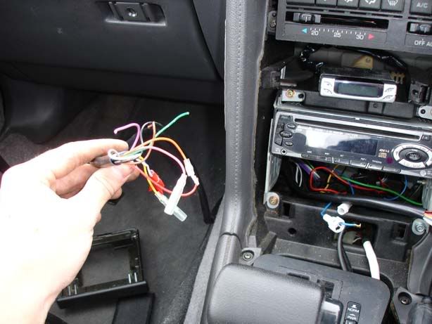
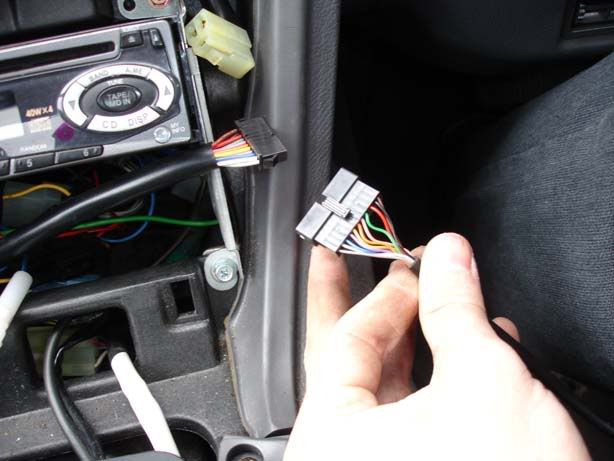
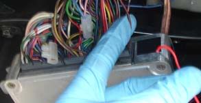
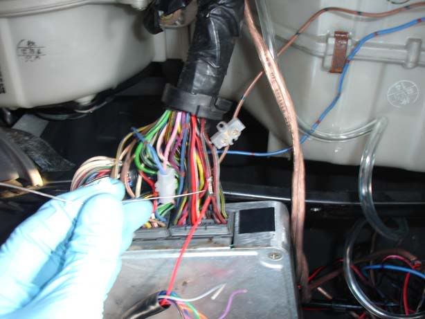
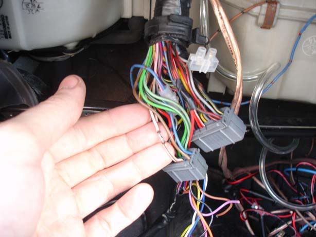
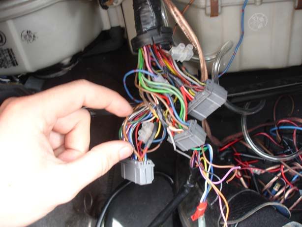
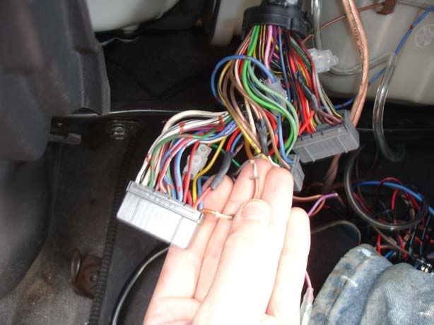
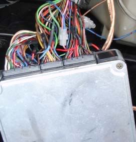
Step 31 - Plug all the connectors back into the ECU

p1329343_1.jpg


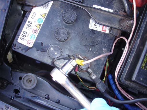
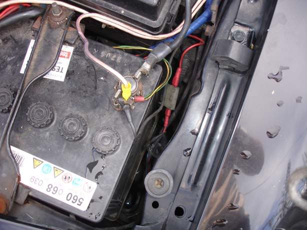
Step 32 - Hook your battery up once again

p1329343_2.jpg


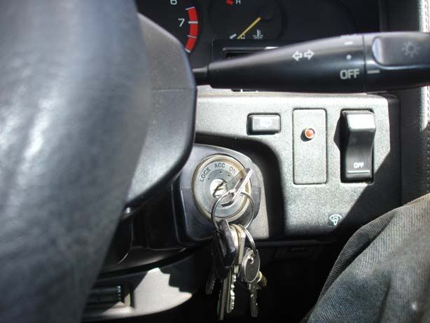
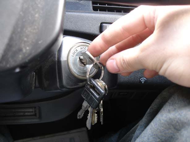
Step 33 - Put your ignition to the ON position - DO NOT START THE CAR! You need to set the SAFC up first

p1329343_3.jpg


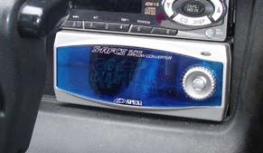
Step 34 - Your SAFC should light up. If not, check all connections are OK. Make sure you have no shorts, bad joints etc

p1329343_4.jpg


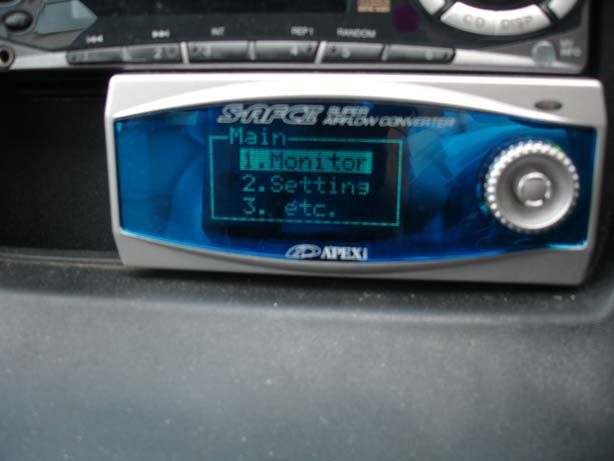
Step 35 - A menu should appear with 3 items on it. You can move up and down by turning the big dial on the right (although it's abit backwards, you turn anticlockwise to go down and clockwise to go up through the lists). The centre button should be moved to the right to enter a submenu and the left to go back

p1329343_5.jpg


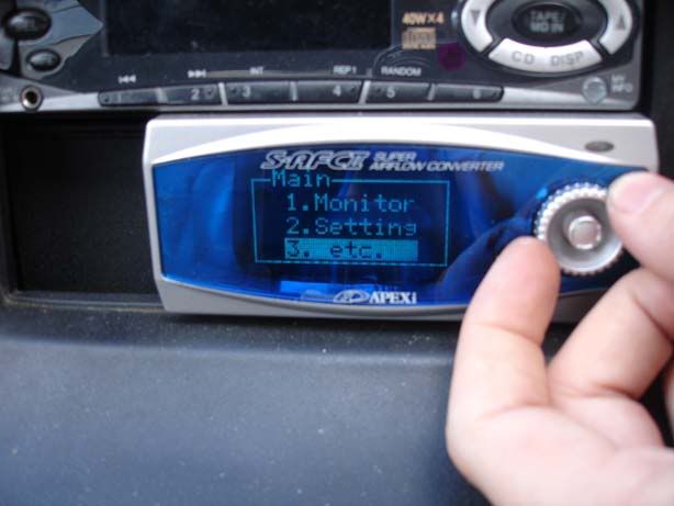
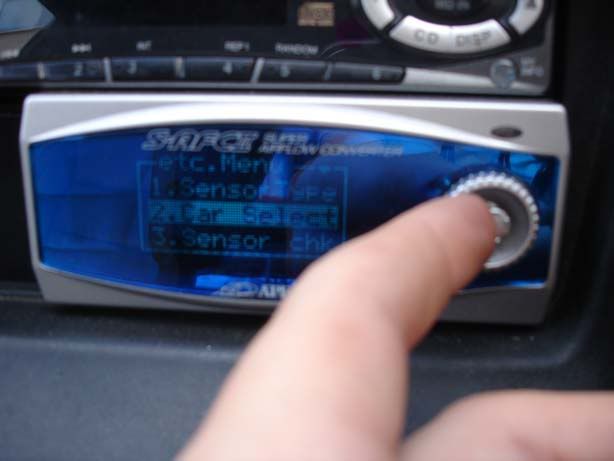
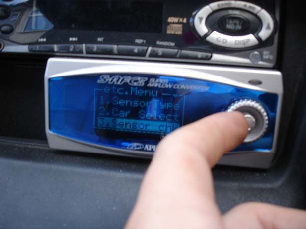
Step 36 - Rotate down to the etc menu item

p1329343_6.jpg


Step 37 - Push the centre button to the right to enter the menu

p1329343_7.jpg


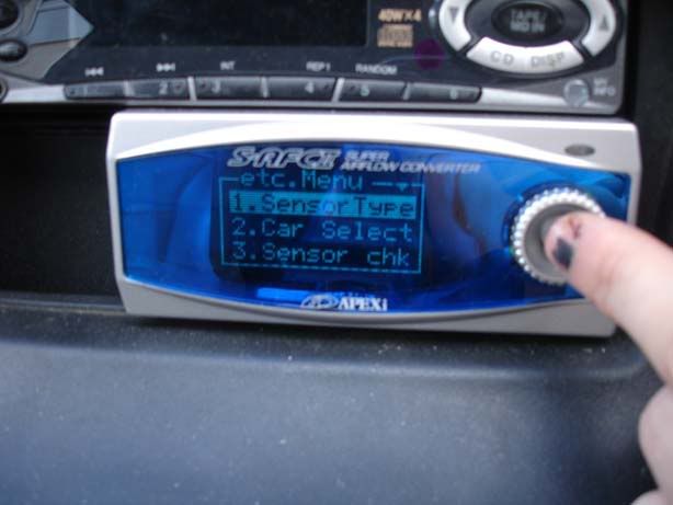
Step 38 - We want to look at the sensor type so go right again

p1329343_8.jpg


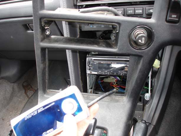
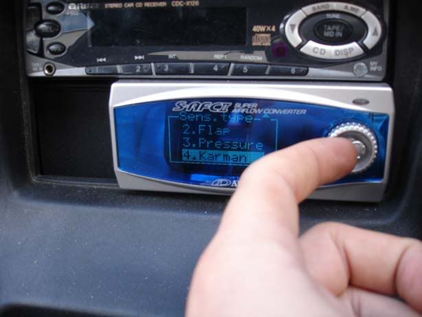
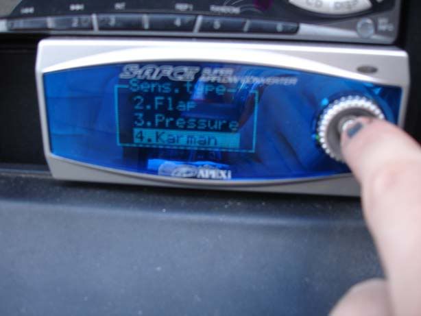
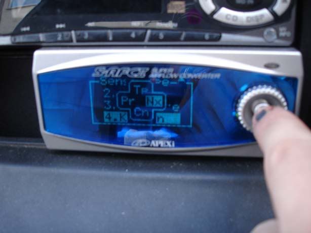
Step 39 - Move up and down through the list (use the dial from step 36 or the button as shown) until you find Karmann (for karmann vortex style AFMs) and then push the centre joystick thingy to the left to return to the previous menu. Alternatively, do it the hard way and press the centre button (picture 1) then choose 'PR' for previous by moving the joystick left then pressing the centre button again (picture 2)

p1329343_9.jpg

p1329343_10.jpg


Step 40 - Next, rotate the dial or push the joystick down to 'Car Select'

p1329343_11.jpg


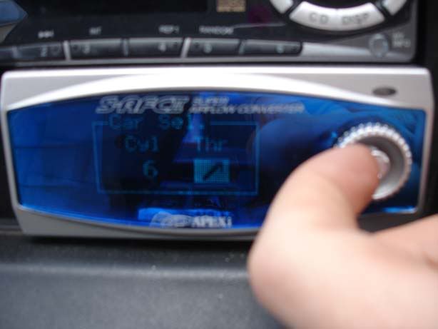
Step 41 - Set cylinder to 6 by moving the joystick up and down then move it right to go to the arrow. The arrow can point up, down or have two ** characters. You want it as shown which means the throttle position sensor (TPS) will output between 0 and 1 volt when shut and 3 to 5 volts when at wide open throttle (WOT).

At this stage there is mention in the manual of self learning the throttle opening but I'm a little unclear as to what they mean. It seemed like you have to hold the throttle closed for 10 seconds then at WOT for 10 seconds so I did this. Hopefully someone will shed some light on this?

p1329343_12.jpg


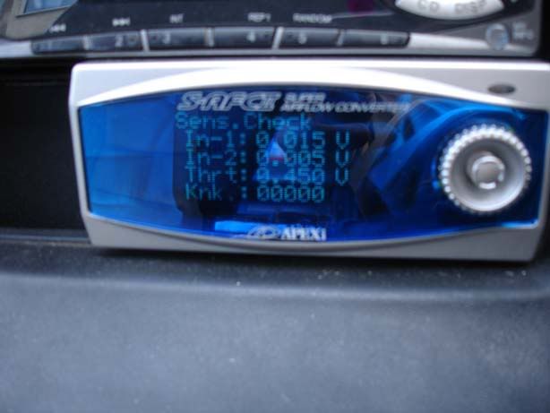
Step 42 - Back to the previous menu, then scroll down to Sensor Chk

p1329343_13.jpg


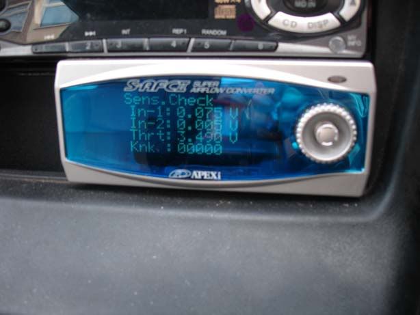
Step 43 - You should see something like this. Check that pressing the accelerator changes the value of Thrt (Throttle) accordingly. If not, you may need to rewire the SAFC so that the grey wire is one position to the right (i.e. instead of being third from the right on the connector it is second from the right). If you see the throttle going up to 3 Volts or more (picture 2) then you are fine and move on to step 44

p1329343_14.jpg

p1329343_15.jpg


Step 44 - Turn the ignition off to store the values

p1329343_16.jpg


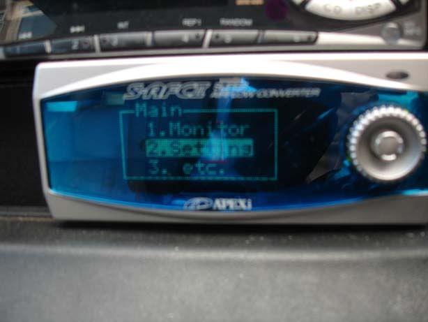
Step 45 - Pop back to the first menu with 3 items on and select item 2 then scroll down to Knk Set and you should see the following screen

p1329343_17.jpg


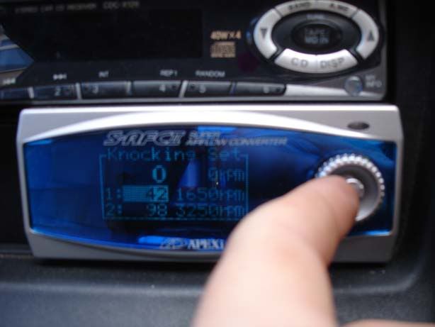
Step 46 - Start the engine and you should be able to set the knock values. Mine were already at the values shown (from a previous install) so I left them alone.

p1329343_18.jpg


Step 47 - At this point I reached the limit of my ability so I hooked the original bullet connectors back together so that the SAFC was making no modification to the fuelling and took it to a rolling road to get them to tune it