
Background
Fitting an amplifier isn't something that should just be relegated to those who like cruising round town centres in the small hours disturbing the locals. Most head units have a relatively low power output e.g. around 15 watts whereas most speakers on the market will start at approximately 50 watts. When you introduce high power components and subwoofers you can easily reach hundreds of watts required to drive them properly.
As standard your car may be fitted with an amplifier but this is prone to trouble and it's generally recommended to bypass it when it fails and fit an aftermarket unit to boost performance. The job of an amplifier is basically to take an input signal (the stereo's signal to a speaker) and increase the power output by effectively injecting some power before sending it to the final destination e.g. performance speakers.
If you read around the subject of amp/speaker selection you'll often find a recommendation to buy a decent expensive unit rather than a cheaper alternative, this is actually sound advice. Myself, I was always tempted by having more and more bits in the system so soon ended up with half a dozen amps and a few subs with several sets of speakers throughout - the appeal of quantity over quality for the same price won me over! As time goes by you realise that a better quality sound is achieved by a few select components set up correctly so pick wisely!
There's a lot of misinformation out there, especially when it comes to speakers. It's important that your amp matches the speaker's output which is measured in watts. When you go to buy a speaker (or amplifier) it will claim huge power figures but in reality they are significantly smaller (Usually at leats half and up to 10 times smaller!). Basically ignore anything that says peak power, you are interested in the nominal value or RMS wattage which is the real world power rating of the speaker. You need to tot up all the RMS values of the speakers, add a small margin and then select your amp(s) accordingly.
Recommendation
As a general guide I'd suggest:
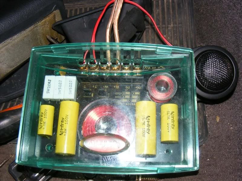
1. Spend your money on the front speakers, buy something special with at least 50 watts RMS, preferably around 100 for a loud but good sound. I really like infinity kappa perfect 6.1s, they have a crossover (special box of electrics that sorts out frequencies and forward to the appropriate speaker), tweeters (for the high frequency sound) as well as the mid/bass unit (the general sound).
2. For the rears I'd go for any 6x9s (oval speakers that roughly measure 6 inch by 9 inch), the quality here is less important and is more a filler in my opinion. I'd look for something with at least 50 watts RMS once again and you can fit two sets if you really want some volume (I did on this install, two sets of £20 from Argos and they sound just fine)
3. Subs are something you can easily get carried away with but for most installs a single 10 or 12 inch sub will provide ample performance, aim for 200-300 watts RMS for a decent sound. Note that you need substantially more power for a sub than for other speakers to produce the high energy needed to move the cone. I do quite like the Sony Xplod subs which are cheap but most branded subs will perform well e.g. MTX, JBL etc.
4. Assuming 100 watts RMS to each front speaker, 50 watts RMS to four 6x9s and 300 watts to a sub you have 100x2 + 50x4 + 300 = 700 watts RMS. I'd be looking for at least an 800 watt amp so it's not being pushed to the limits. For my install I'm using two Phoenix Gold (very good) QX2350 amplifiers which can supply the 100 watts RMS to each of the front speakers and one will be 'bridged' (two channels joined together) to power the sub with ~300 watts. Finally I bought a Sony XM-SD46X amplifier which can give me 4x60 watts RMS to my 6x9s which is great at £50 for a brand new amplifier!
Channels
The next thing to introduce is the number of 'channels' which is the number of speakers an amplifier can drive e.g. a 4 channel amplifier can drive 4 separate speakers. To complicate this you can use bridges, sometimes confusingly referred to as crossovers because you cross the wires over, where you combine one or more channels to power fewer speakers but with more power e.g. a 2/3/4 channel amplifier could be used to drive 4 speakers at a given value, for example 100 watts. Alternatively you can run in '3 channel' mode where you drive two of the speakers at 100 watts then combine the other two channels into one more powerful channel at, say, 150 watts. Then you can go further still and run 2 channels, both bridged to provide 2x150 watts.
OK so we know you need to check the RMS rating of speakers, the wattage of the amplifier must be big enough to cater for this and you understand that the number of channels is important with regards to selection of an amplifier.
This is a bit of an overview of a lot of topics because you can get really bogged down with the detail - if you start thinking about dual voice coil subs and monoblocks with class d efficiency then you probably don't need a basic guide for fitting an amplifier anyway! Anyway, on with the next bit - ohms!
Ohms
Ohms are a measure of resistance (the amount a component resists the flow of electricity). For in car entertainment (ICE) it is referring to impedence which is like resistance but varying with frequency. You don't need to worry too much about the physics but suffice to say the speaker and amplifier's impedence should be matched i.e. a 4 ohm speaker should be powered by a 4 ohm amplifier. You should consider this when buying both speakers and amplifiers.
Typical values are 2 ohm, 4 ohm and 8 ohm with 4 ohm being the most common. Amplifiers are usually stable at 4 ohms and often 2 or 8 ohms. Generally to start with look for 4 ohm speakers and a 4 ohm stable amplififer.
The lower the impedence (number of ohms), the more power is produced as a general rule. A 2 ohm capable amp is the minimum load supported, this is per channel in stereo mode. If you bridge channels the stability is the sum of each channel e.g. a 2-ohm stable 2 channel amp can be bridged into a single 4-ohm mono channel
If you have a 2-ohm stable amp, you can utilise the extra power by wiring your speakers in parallel (wire two sets of 4 ohm speakers to the same + and - terminals on the amp). Due to the extra power being produced the amp will get a little hotter but a 2-ohm stable amp can disperse this heat properly.
Conversely you can wire speakers in series to increase the load an amp sees. This makes the amp run cooler but produces less power so is rarely used. If you want to do this you simply run from your + amplifier terminal to the + speaker terminal then from the - speaker terminal to another speaker's + terminal. This second speaker then runs the - terminal back to the amplifier - terminal in a daisy chain fashion
Wiring
Supply wiring to an amplifier is of great importance, if you do this badly then you risk damage to yourself and the components (very easy to blow amplifiers by doing silly things). Selecting the correct 'gauge' or thickness of wire is also important. The lower the gauge (often called AWG after American wire gauge) the thicker the cable and the more current it flows. For a really large system you could go as low as 0 gauge cable but typically a 4 gauge or 8 gauge cable will suffice. To determine the cable size you work out the number of amps it requires to pass and then look up the appropriate cable thickness.
This is a rough guide I shamelessly lifted:
Wire Size|Load Capability
0 gauge|334 amps
1 gauge|265 amps
2 gauge|210 amps
3 gauge|167 amps
4 gauge|132 amps
5 gauge|105 amps
6 gauge|83.4 amps
7 gauge|66.2 amps
8 gauge|52.5 amps
9 gauge|41.7 amps
10 gauge|33.1 amps
11 gauge|26.3 amps
12 gauge|20.84 amps
13 gauge|16.54 amps
14 gauge|13.13 amps
15 gauge|10.42 amps
16 gauge|8.27 amps
17 gauge|6.56 amps
18 gauge|5.21 amps
19 gauge|4.13 amps
20 gauge|3.28 amps
21 gauge|2.60 amps
Current and power
Right, now we've mentioned another thing - amps (amperes/amps are a measure of current). This one is also very important and is directly linked to the watts (power) we mentioned earlier. Your car stereo is running off a battery, this battery will sit at around 12 volts when the engine's not running and then rise to about 14.8 volts when the alternator is doing its job. I'm going to assume you only use the stereo when the car's engine is running (or you need to look into secondary batteries and split charging systems) and we'll assume a voltage of 14 volts to be conservative.
Right so we have watts, amps and volts how are they related? Watts / volts = amps and we know volts = 14. So we use the total number of watts in a system, say 700 watts RMS like we used earlier then divide by the voltage (14) which gives us 700/14 = 50 amps. We therefore need cable capable of carrying at least 50 amps of current to supply this (as always you'd add an overhead so get a cable capable of carrying at least 60 amps to be safe nad probably more like 100).
If you intend to expand the system then add plenty of overhead in your wiring and over spec your amps so you can add more speakers etc as necessary. Also keep in mind that amplifiers are not 100% efficient and people recommend up to double the current requirements for a given wattage e.g. out 50 amps would be increased to 100 amps to genuinely supply the 700 watts we require! Read the technical spec of your amplifier to find out more
Amp classes
The electronics of an amplifier determines its 'class'. They are loosely defined as follows:
Class A - High quality sound but high heat production, not used in automotive applications normally (often a class A advertised amp is actually class AB)
Class AB - Reasonably efficient, low distortion and high reliability, your normal car amp
Class D - Even higher efficiency, less heat and less current draw than AB but more distortion. Perfect for subs where you won't detect the distortion
Class T - Hybrid of AB and class D amps
Filters
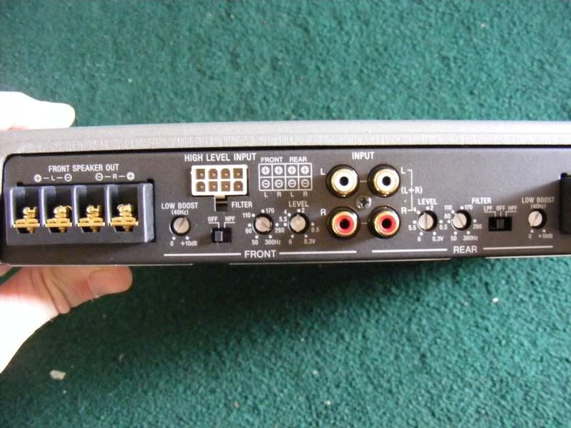
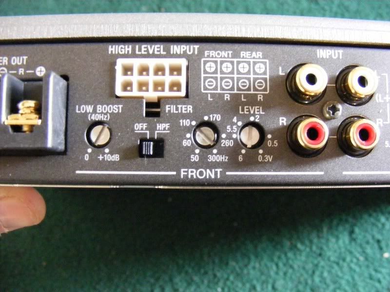
Certain speakers are better at reproducing certain frequencies e.g. a sub will produce low frequencies well whereas a tweeter (the tiny speakers) are best suited to high frequencies. You can filter the sound to only let certain frequencies reach your speaker using low pass and high pass filters. A low pass filter will only pass low frequency sound to the connected speaker so should be used for a sub woofer. A high pass filter allows high frequency sound to reach the speaker so would be used for a tweeter. This is amplifier specific, some have it, some don't - it should come with instructions to help you set the frequency of this filtering but I thought I should mention what it is to be complete. Below is a picture of what you may get (note the switch with off and hpf (high pass filter) for one channel and lpf (low pass filter), off, hpf for the other channel.
One point here is that low frequency sounds are less directional than high frequency sounds, what this means is that the direction you face your sub woofer is of little importance (people often prefer them facing the rear of the car). With tweeters, however, the position is of great importance and makes a big difference ot the sound. The recommendation is often to have them right next to your ear or directly facing it with one speaker either side at equal distances from your head (or as close as you can). The kick panels are one favourite as well as the door cards.
Signals
Getting the output of your head unit to the amplifier can range from very easy to slightly perplexing. The options are:
1. Your stereo has RCA outputs in which case you're laughing and simply run the RCA lead from stereo to amplifier, this is the easiest and therefor imho best route and what I have done in this guide
2. The head unit supplies preamp outputs, run these straight to the amp or a patch cord (see below)
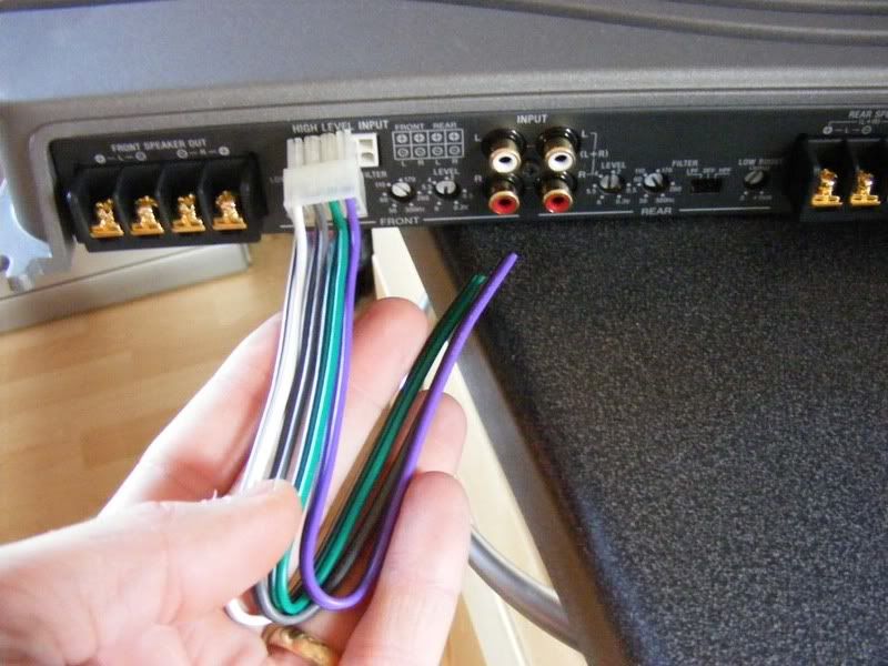
3. You have a bog standard factory stereo with no feeds for an amplifier, what do you do? Well, purchase an amp with speaker level inputs (high level input in the pictures below). You can then wire the stock speaker wires to the amp and use these signals to drive the amplifier.
If you don't have speaker level inputs or preamp inputs on the amplifier you can get an RCA patch lead with line converter which will allow you to convert the signal from the standard speaker wire to an RCA feed to an amp.
Important!
Your electrical system is over spec'd as are most/all cars i.e. there's a headroom available between what the alternator kicks out and what the car actually uses. IIRC the Supra has about 20-30 amps 'free' which is enough for about 300-450 watts of RMS power. If you start trying to drawy 2000 watts then you can expect to kill the alternator, trust me I have done .. twice. If you are going to build a massive install then you really need to consider having a second alternator or a rewired standard one with a larger output e.g. over 100 amps.
When the bass kicks in and your headlights dim then you know your system is really struggling, people will tell you to fit a power cap (capacitor) to handle this but I am not a fan of this. Basically the capacitor stores a bit of extra energy and when your alternator/battery is unable to deliver power fast enough the capacitor steps up. Unfortunately the capacitor is then discharged and will become another draw on the system to prepare for the next burst from a sub.
One recommended approach is to have a secondary battery for the stereo which will only take charge when the primary battery (your normal battery) is fully charged. This is achieved by a 'split charging' system which monitors the status of the normal battery and then allows the alternator to start charging the second battery when appropriate. The big benefits to this approach is that you should never find yourself with a flat bettery due to the stereo drawing too much power and also the alternator should not be over worked.
If you do decide to go donw the split charging route then I recommend you look into Optima or similar deep cycle batteries. Even if you don't go for the second battery it is worth considering a deep cycle battery as your primary cell. The main reason you would go for a deep cycle battery is that you can discharge it far more than a standard (lead acid) cell without it becoming irreperably damaged. As I'm sure a lot of you will know, once a standard battery has been left for a long time and discharged too much it will never recover no matter how long you put it on charge. The deep cycle technology allows for vast amounts of the battery's energy to be depleted whilst still recovering to full capacity when it gets charged up.
So, recommendations for power supply are
1. Get a high power alternator
2. Get an Optima deep cycle battery
3. Use a split charging system
The alternative is that you just run off the standard alternator but I warn you to expect problems with multiple amps and subs
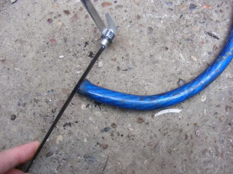
1. This is rapidly turning into an article rather than a guide so we'll start some practical work and throw in more theory as we go! I'm going to show how to fit a system with several amps and one 12 inch sub + front and rear speakers. For my install I'm going to use 0 gauge cable to allow for massive performance and plenty of future expansion (plus I had some zero gauge kicking around!). I don't anticipate any of you needing cable this large and 4 gauge is probably as big as most will go but the wiring work is identical.
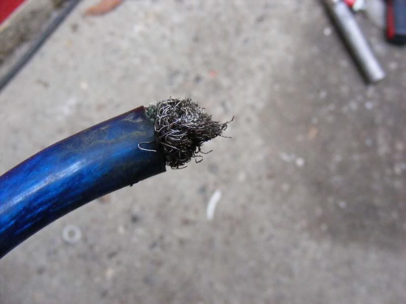
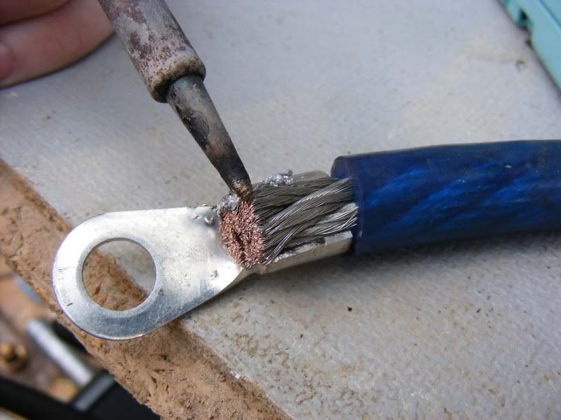
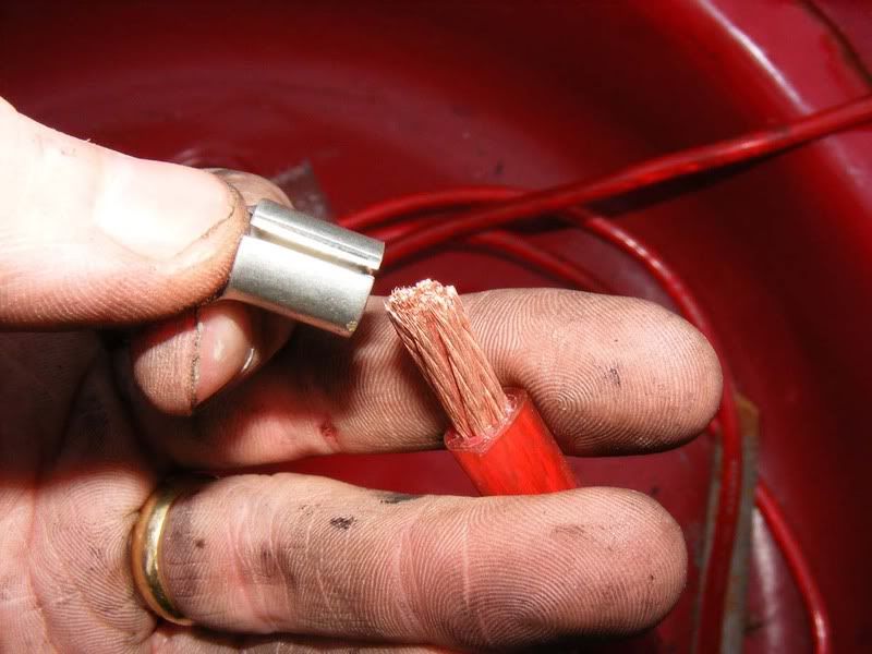
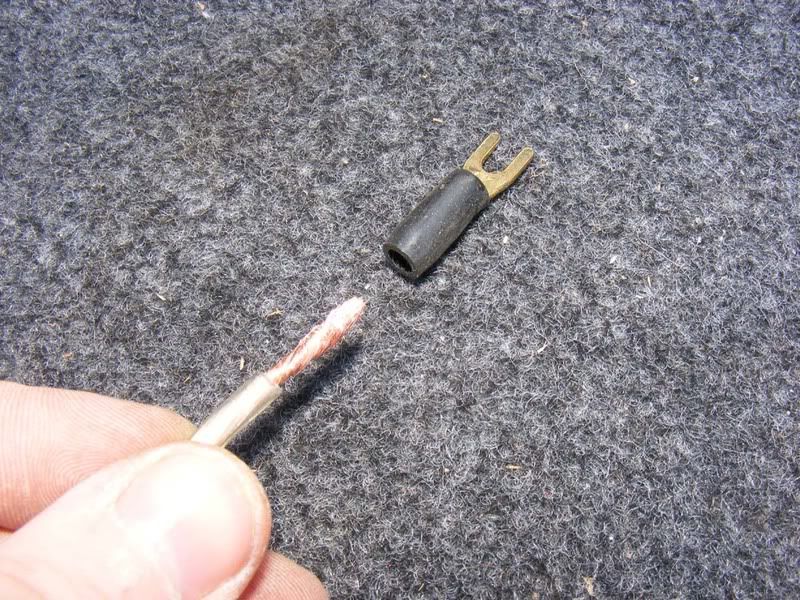
Here's a picture of some scrappy looking cable, this is not what you want to be using for your connections so we'll start with proper terminations.
2. Use a pair of scissors for smaller wire but in my case a hacksaw to cut back to a clean wire
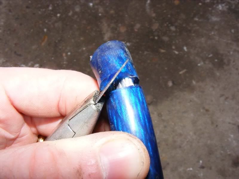
3. Now run a stanley knife blade around the outside of the sheath. Careful not to cut the core of the wire inside - you'll get the hang of it after doing a couple. Ideally you cut just deep enough so that when you flex the outer insulating material it splits and reveals the metal beneath
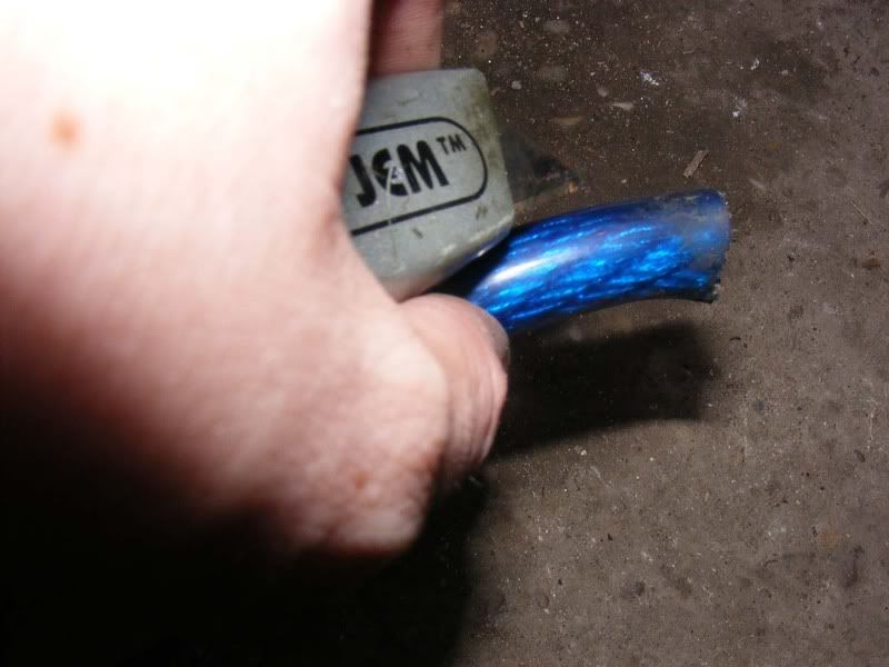
4. Lever the newly separated outer core off the wire
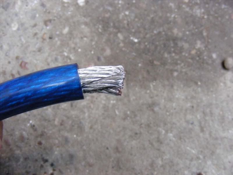
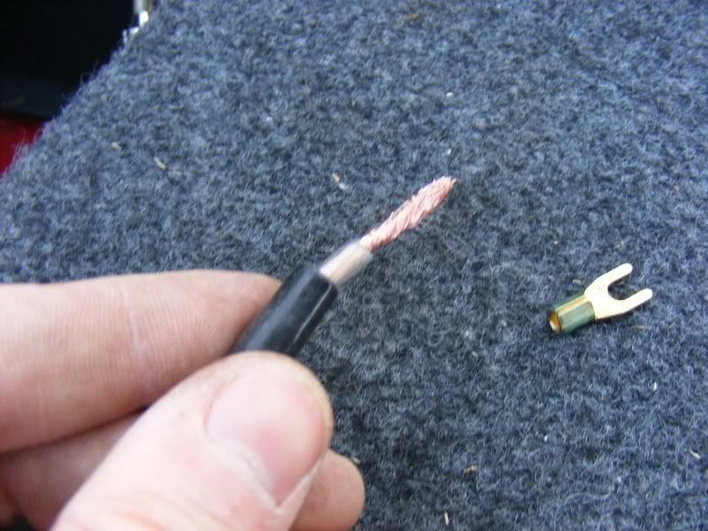
5. Now you've exposed the core, if necessary twist it two prevent any rogue wires sticking out, mine was pre-twisted
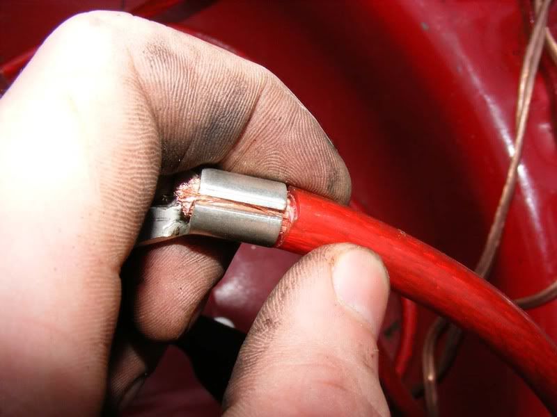
6. Now grab yourself some suitable connectors, these usually come with an amp wiring kit which I highly recommend for beginners. If you get the gold connectors then they are usually pretty expensive but make good connections and importantly are easy to shape and crimp. Expect to pay extra for them though, the cheapest I usually get them for is £1 each
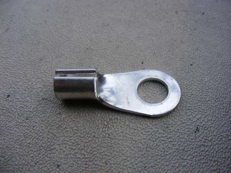
7. Where necessary, open up the connector so you can fit the wire in, this can be done with mole grips or gentle work with a hammer and flatblade screwdriver (only for steel ones, mole grips will be fine on gold)
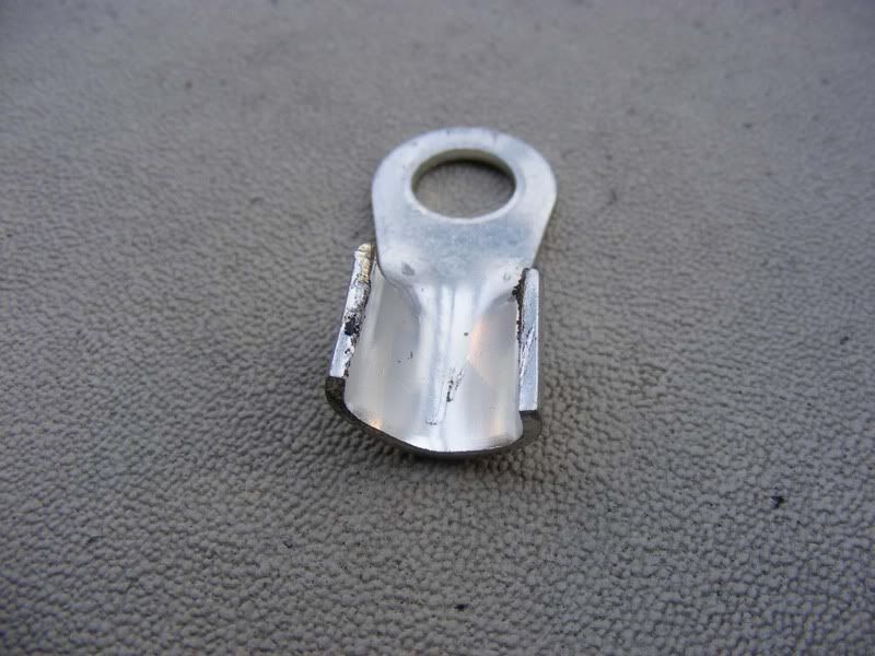
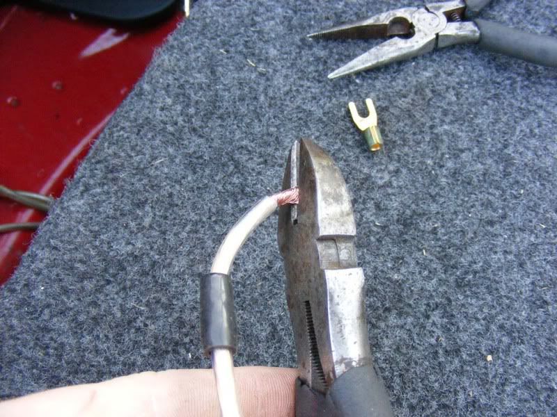
8. Fit the connector around the cable
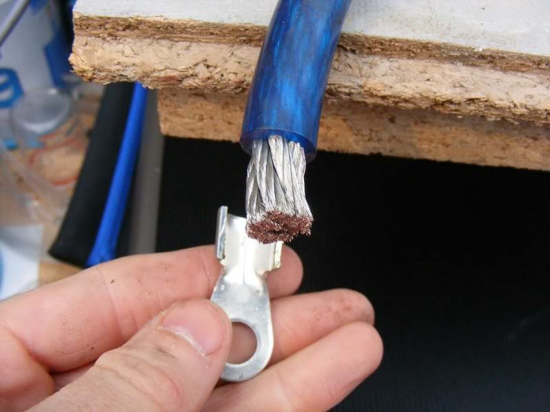
9. Now clamp securely around the cable
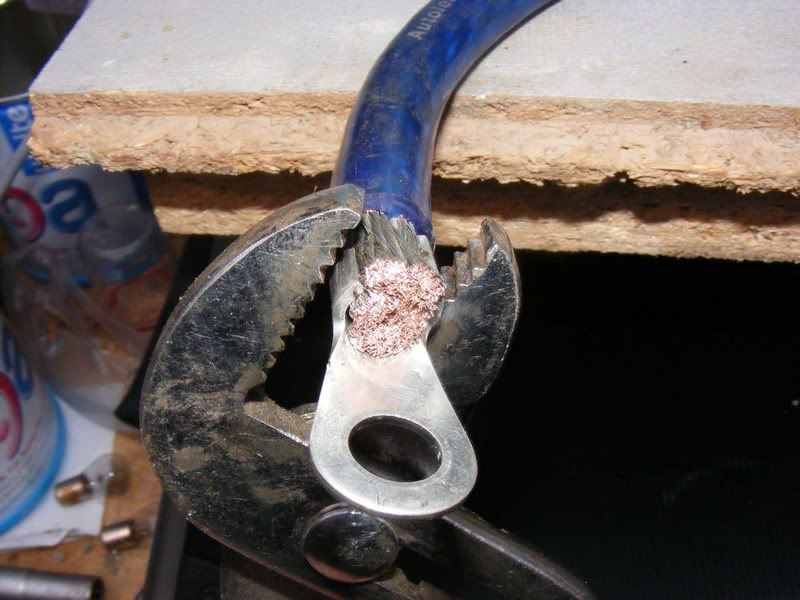
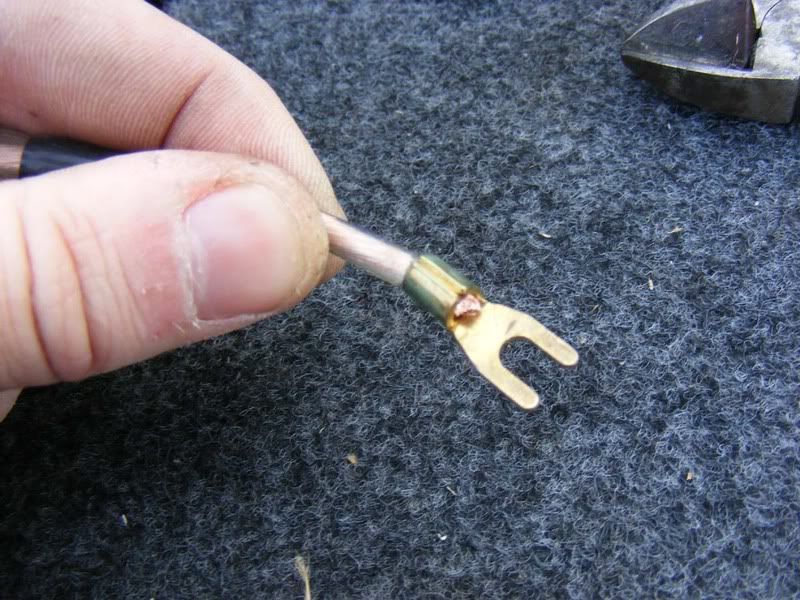
10. For best results, solder the cable to the connector too
11. Fuses - very very important! Do not skimp on fuses at any point in the system, I guarantee at some stage they WILL svae your behind! Drop a cable orshort a screwdriver to an amp body etc and suddenly you have a problem - unless you fit a fuse that is. First things first, as soon as you've left the battery within 12-18 inches fit a fuse capable of supplying the whole system. In my case I had a 150 amp fuse which is able to supply 150 (amps) x 14 (volts) = 2100 watts RMS!
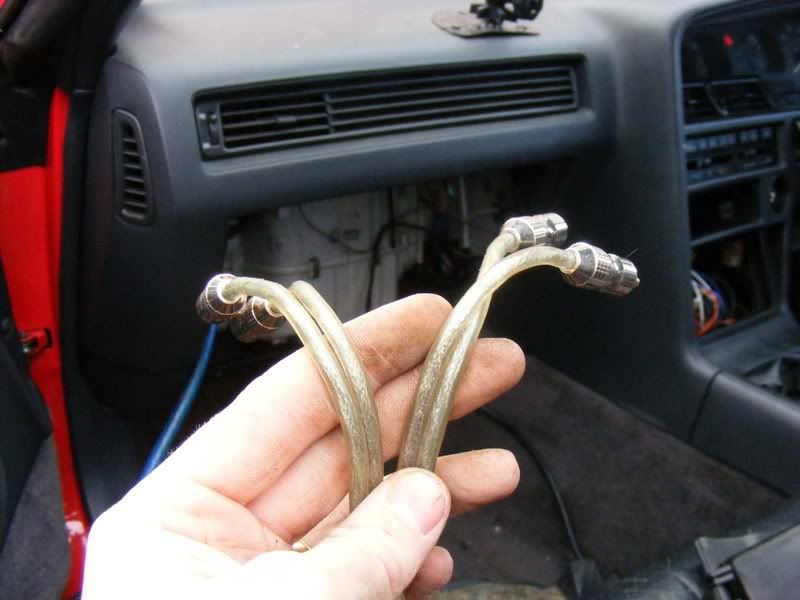
Always fuse just after the battery then run your cable to the amp and fuse for each amplifier you supply. To start with you need a cable which goes from the battery to a fuse block (amp wiring kits normally have an inline fuse provided), for my install I had an external high ampage fuse so require 2 terminations as documented in the first 10 steps. You'll end up with something that looks like this
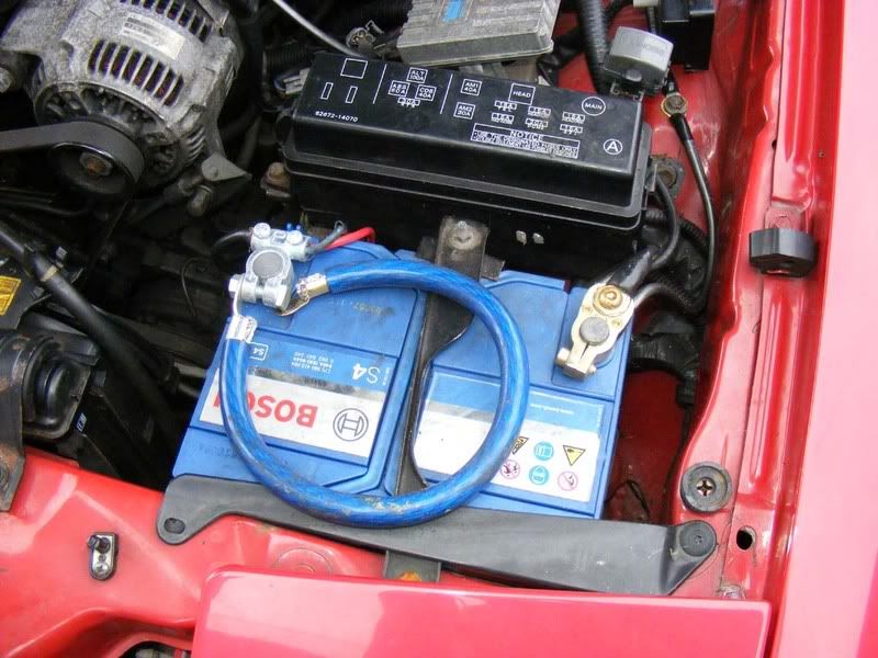
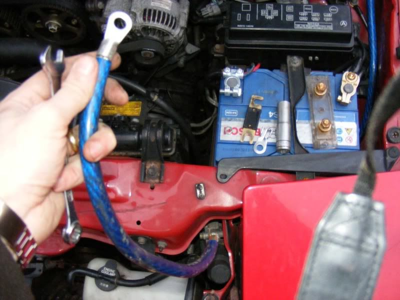
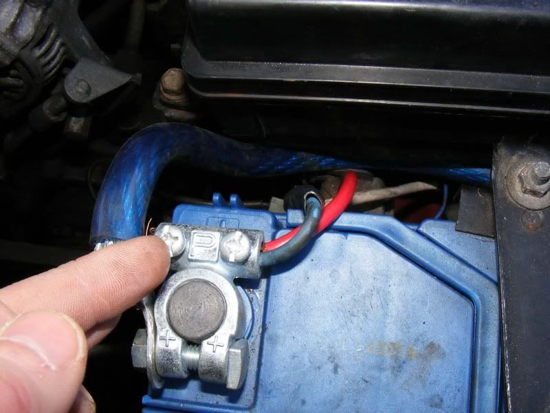
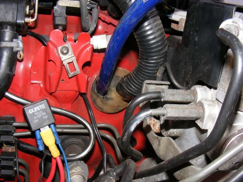
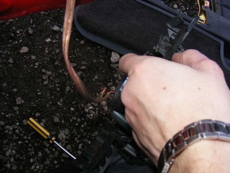
12. The cable from the battery terminal then goes to a fuse box (shown on the right hand side of the battery in the picture). Then the ring terminals are used to join the wire from the battery (I'm holding it in the picture) to the main power supply that will run through the car. On the left hand side of the battery is the fuse I am using which slides into the holder and bolts down with 2 14mm nuts. I suggest you don't fit any of the fuses until you have routed all the wiring to avoid accidents during installation
13. You need to consider where your amp(s) will be located e.g. under seats if you can fit them or in the boot. When mounting the amplifier ensure you leave it in a place where it is in 'free air' i.e. there's nothing directly on top of it because the amplifier uses the housing as a heat sink to cool itself down. Don't mount an amp upside down or the heat goes out the cooling fins then straight back towards the amp
To reduce the chance of noise pickup don't mount the amp onto the car's metalwork, either go on the carpet or make a simple MDF platform to mount it to (this is preferable so it doesn't fly around the boot!). 'Ground loops' are to be avoided which is where there are multiple ground paths for one amp.
If you do get noise problems then you can do things like checking the resistance between the RCA sheild and the head unit ground and if necessary tie them together as well as various other checks. Grounding is often the key to pickup. Also try unplugging the antenna and see if that cures it, if so you can get an antenna isolator. A properly installed system will usually avoid interference and 'alternator whine' though.
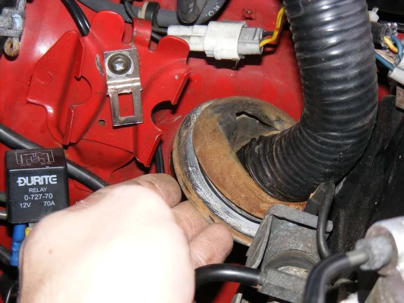
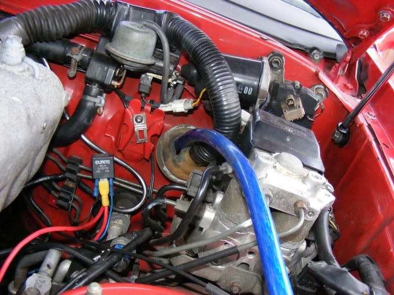
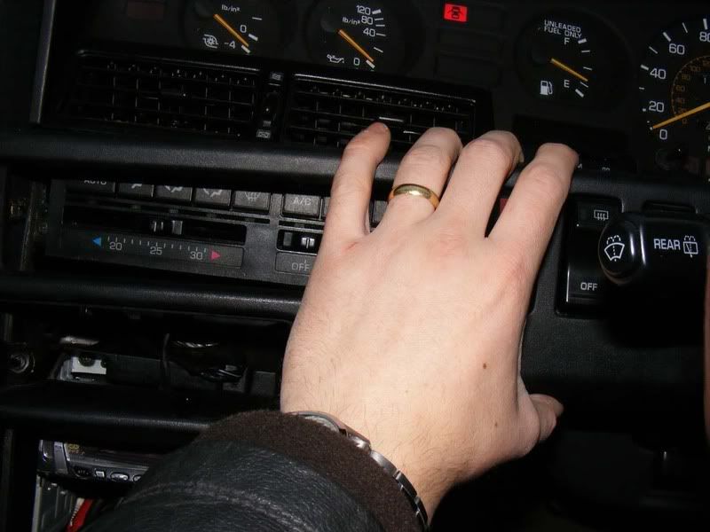
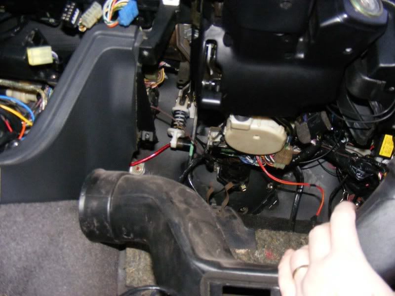
In my opinion the only suitable place in a Supra is really the boot so it's a case of running a power cable from the battery at the front of the car all the way down to the boot. Thankfully there's a perfect grommet available which is the main harness to the ECU.
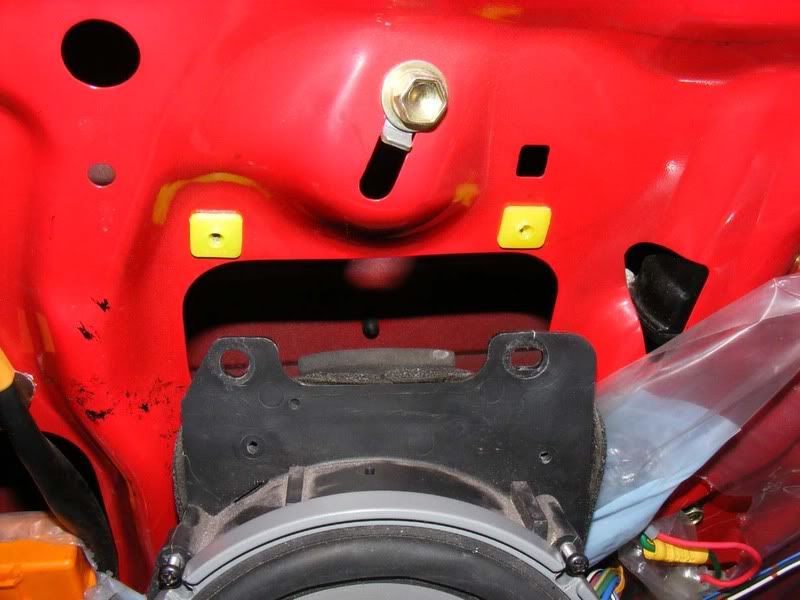
Locate the rubber grommet on the firewall as shown and make a slit in it using a stanley knife
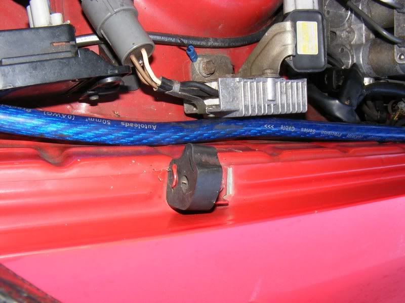
Note: If you wish to run the power cable down the other side of the car, there is a grommet for the clutch hose which is suitable
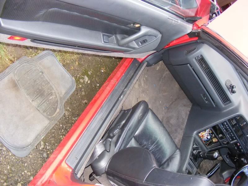
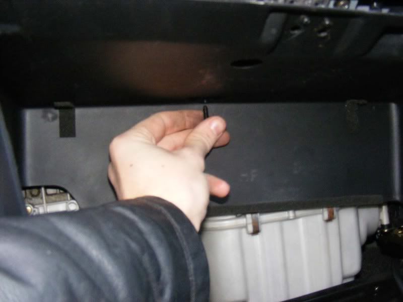
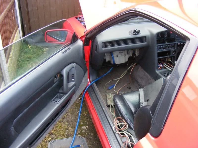
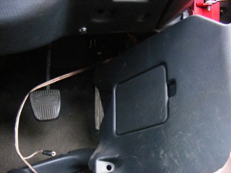
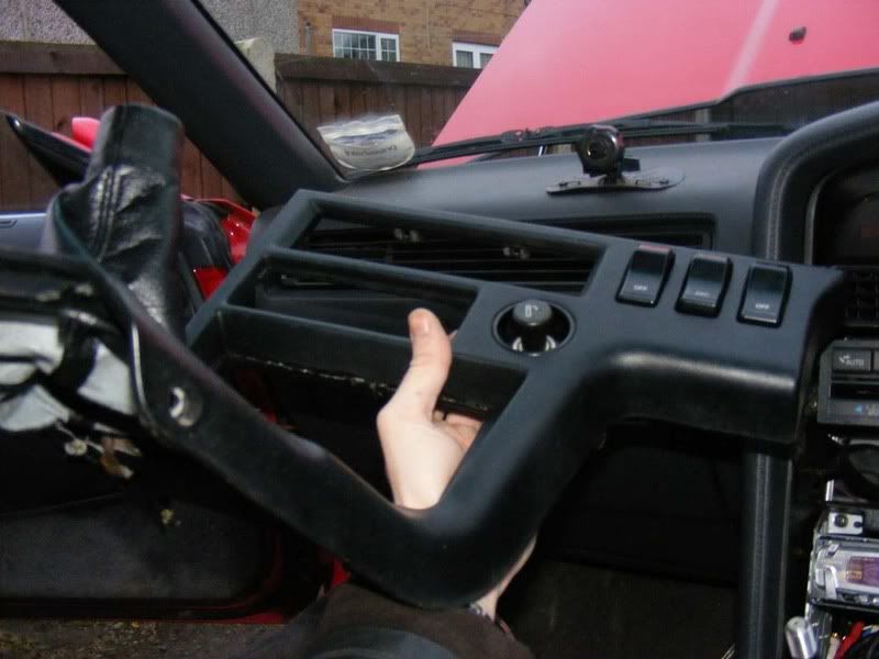
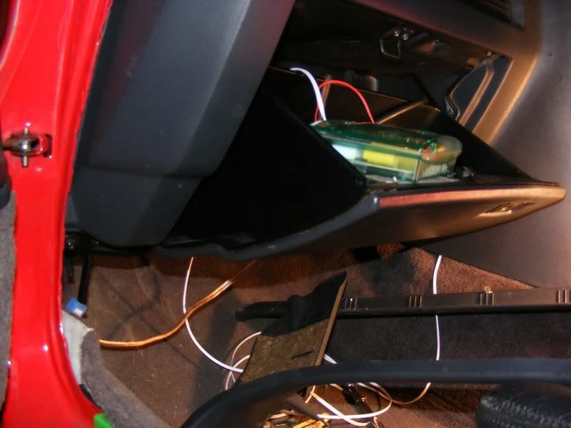
14. Now it's time to work inside the car, whip your mat out and get on your knees
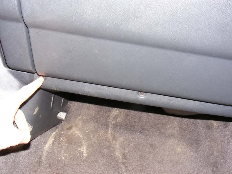
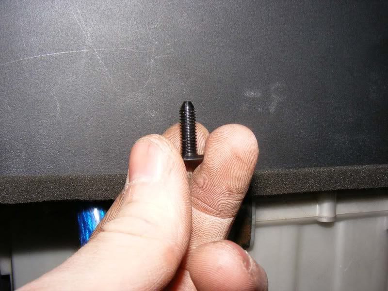
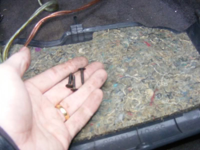
15. Remove the 3 screws holding the cover underneath the glove box
16. Slide the cover out of the way

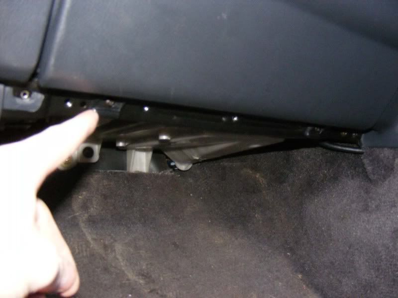
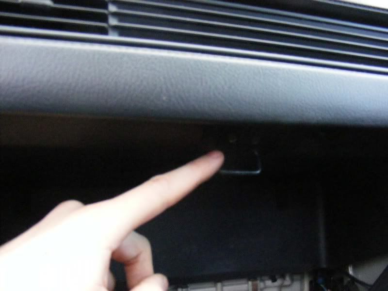
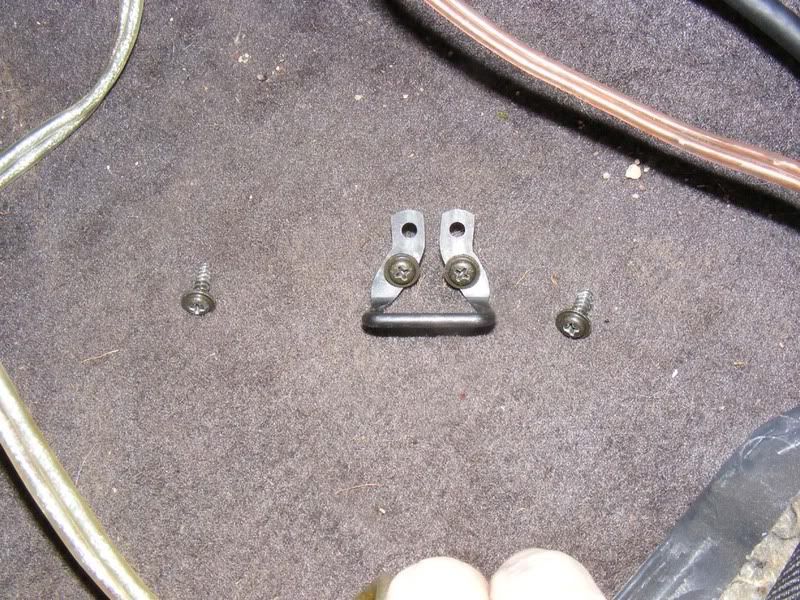
17. There are two black metal brackets that hold the glove box in place, undo the two philips screws that hold these in place
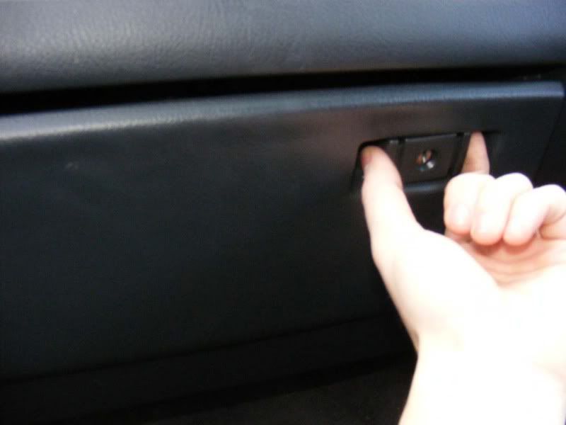
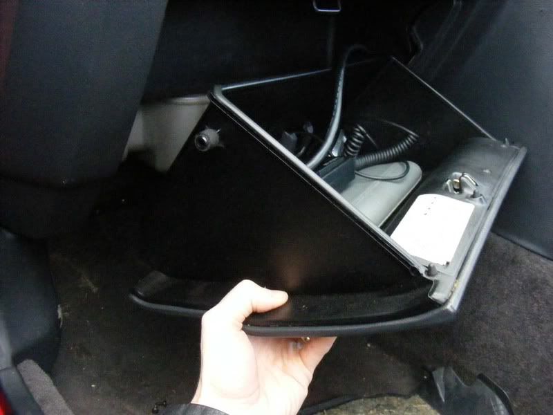
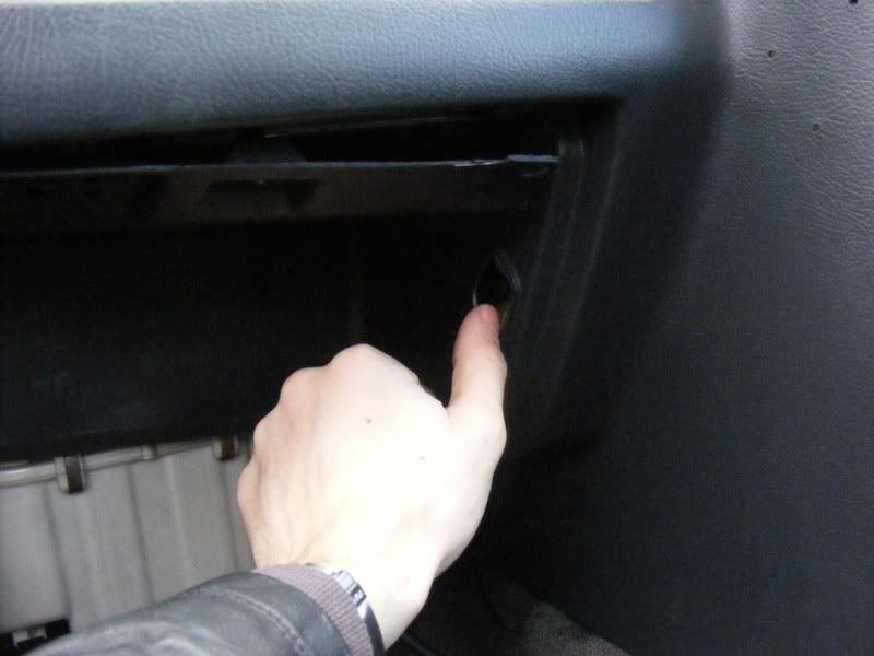
18. Now release the glovebox catch and you should be free to remove it
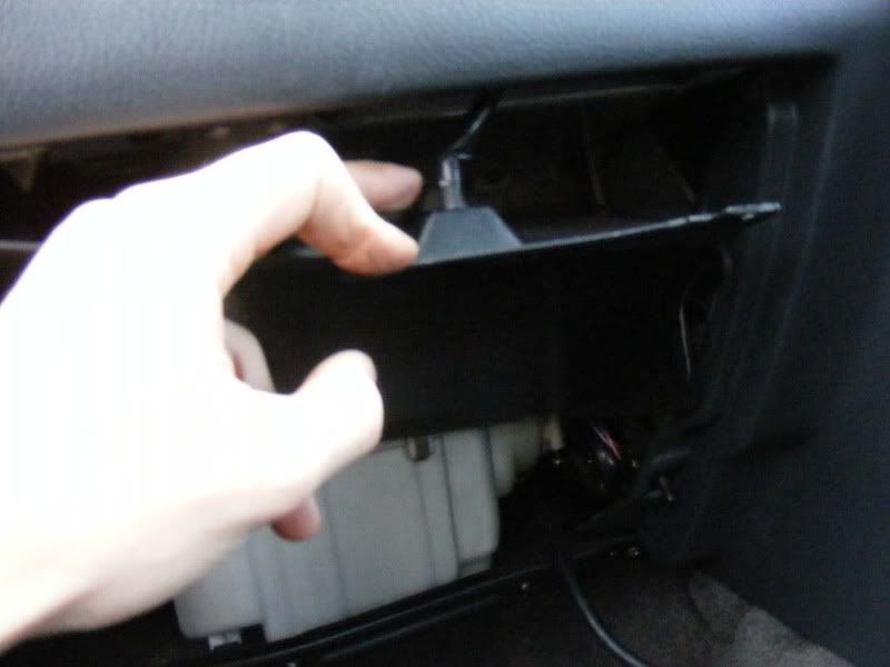
19. Slide the glovebox out sideways as shown
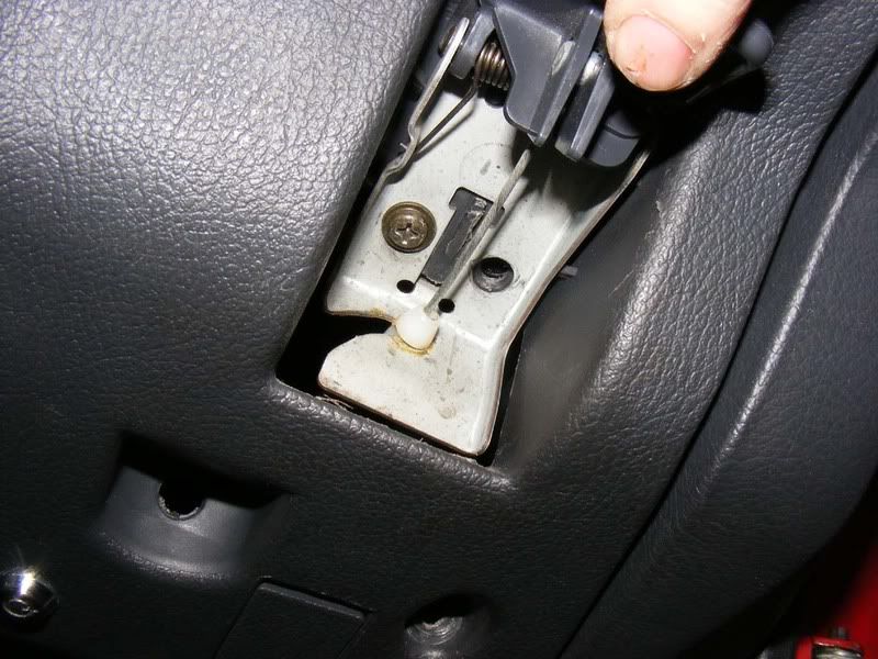
20. Now you need to remove the catch mechanism that is held in by a further 2 screws and there are 2 more screws at either side of the catch
21. The flexible plastic can be pulled out on one side and eased gently down
22. Don't forget to twist and remove the internal light for the glove box
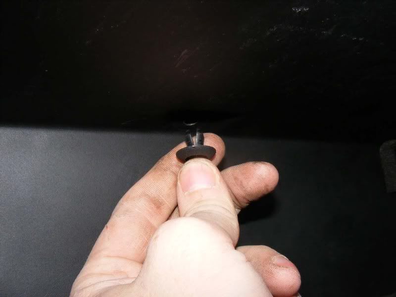
23. Remove the plastic screw at the back of the cover then remove completely
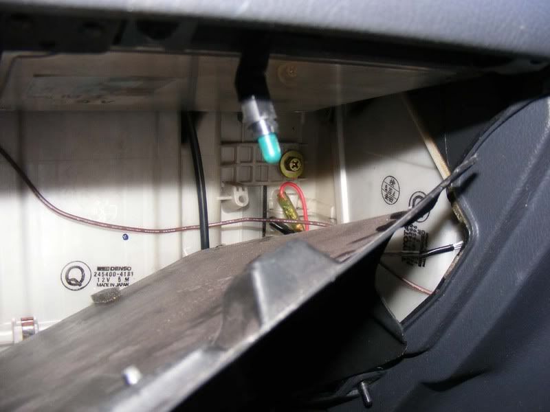
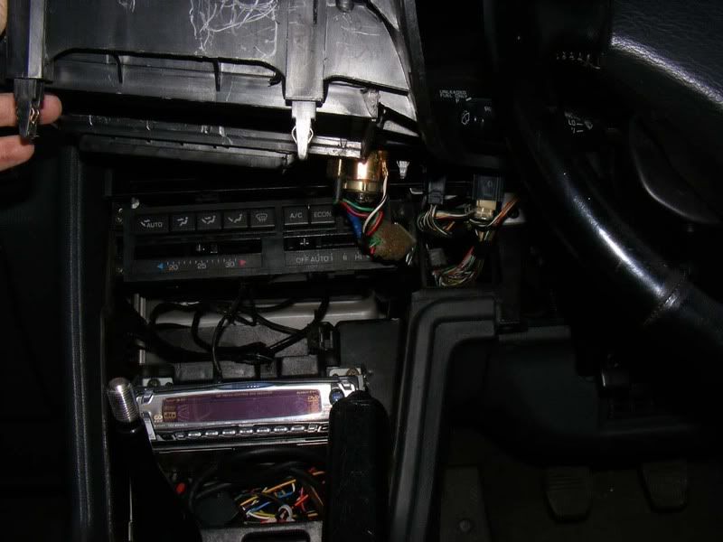
24. You now have access to the ECU, ABS ECU etc. Thread your wire to follow the routing of the big loom as shown
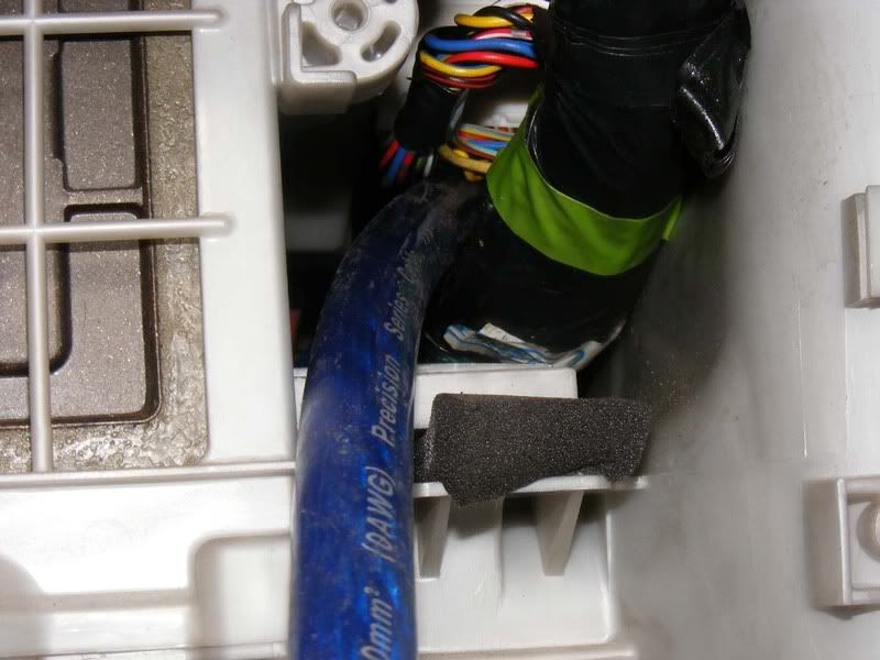
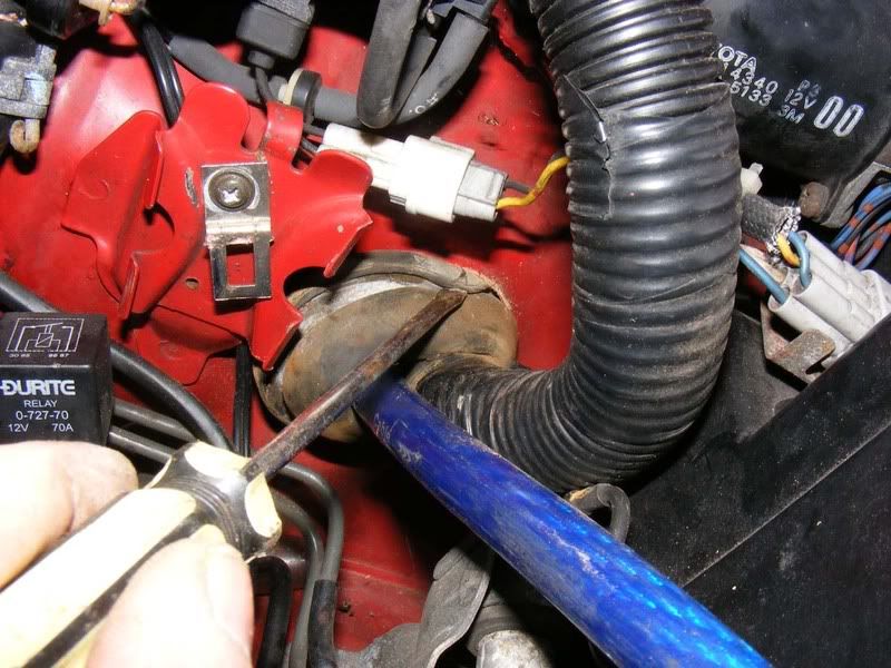
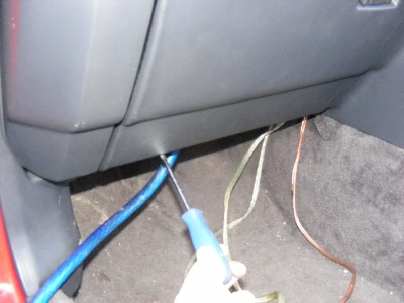
25. Remove the grommet completely (a flatblade screwdriver can be carefully use to do this - it is stretchy but don't stab it too much or you will pierce it)
26. Once you've pulled the grommet up the loom you'll be able to see in the hole and hopefully locate your power cable you fed through (you can obviously do this the other way if you prefer so thread the cable into the car from outside
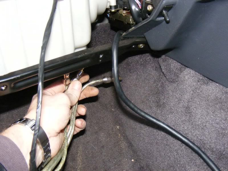
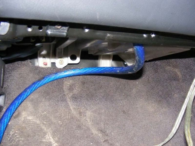
27. Pull the wire through, thread it through your slit in the grommet and ensure you have enough wire in the engine bay to reach your fuse at the battery terminal. Note you will want to route the wire in the engine bay along the bulkhead away from any moving parts and the radiator where it could be melted.
28. Once you've finished pulling the wire through, replace the grommet using a screwdriver again as shown. Start by hooking in the bottom of the grommet and side closest to the wing which is awkward to get to. Then you can use the screwdriver to force in the side you have best access to. The second picture shows the refitted grommet
29. While we've got some good access we should start to route some of the speaker wires which run from the head unit (the stereo itself) to the amplifier. These wires are typically 'phono-style' leads which are known as RCA leads (after the Radio Corporation of America who designed them). These leads run striaght from the head unit and provide a quality signal to the amplifier. You should ensure that any head unit you buy has at least one set of RCA outputs (connections for RCA leads to fit). Typically you will have up to three RCA outputs, the front speakers, the rear speakers and a specific subowofer output. Also, your amplifier should have RCA connections although there are alternatives if you have an amp without RCA connections but that's a separate topic.
The best RCA leads will be 'oxygen free' and once again, the more you spend the better the lead. In my experience the mechanical quality of the more expensive leads is significantly better but I can't tell any sound quality differences. People known as 'audiophiles' get very anal about all the connections and cable qualities but to you and me it makes such a minor difference it's not worth spending hundreds of pounds on RCA leads - £10 should buy a more than adequate set but again, these are usually supplied with the amp wiring kit.
Note you should read on and decide which side of the car the RCA leads will fit before doing this
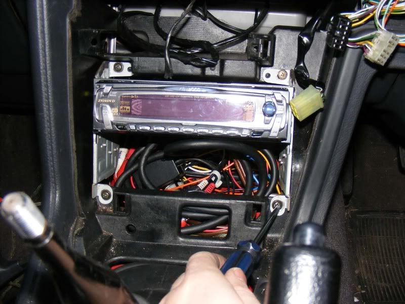
30. Feed the RCA leads up from under the glove box to the area behind the head unit (see the guide for fitting a stereo for details on removing the head unit so you have access here)
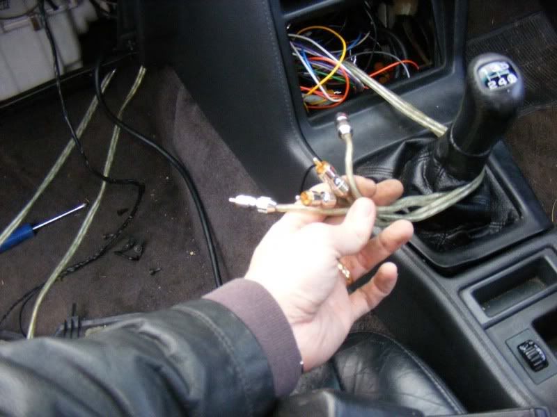
31. Once you've oruted your RCA cables and power wire out you can start putting the glovebox back together - note I have the zero gauge cable and 3 sets of RCA leads (front, rear and sub) to route.
32. Pop your glovebox light back in and twist to secure
33. Fit the plastic expander from the back of the cover (removed in step 23) then re-fit the screw
34. Now pop the catch back on and the two screws either end of it
35. Clip the glovebox into the catch and push the black brackets back over their dowels before fitting the 2 philips screws
36. Finally slide the lower cover back in place and put the 3 screws back in
37. For now, simply route the cables out of the way so we can get them to the boot - by the time you finish none of this should be visible but initially just run the cbales over the seats to the amps.
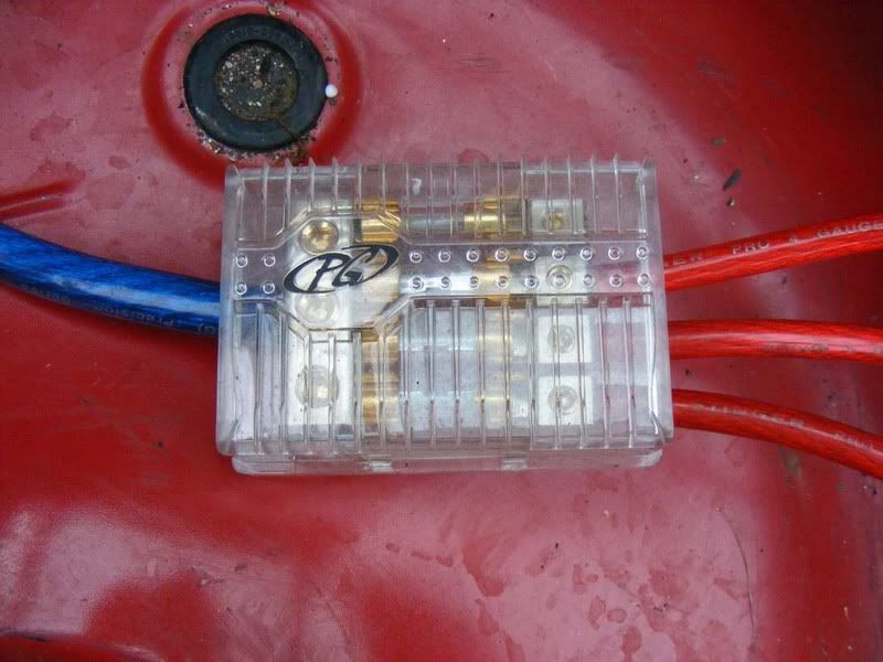
38. When running multiple amps (which is quite normal) or if you plan to upgrade to another amp in the future, I suggest you jump straight in with a distribution block as shown in the picture. These basically take a single feed from the battery (which is your thickest power cable that supplies all the amps) then splits the supply off through a fused link to each of the individual amps that normally have smaller power lines. In my case I drop from my single 0 gauge feed to 3 lots of 4 gauge feeds (again, this is very large and I expect most installs to take a single 4 gauge feed to several 8 gauge supplies).
The benefit of a distribution block is that if you have a problem on 1 amp it just pops the fuse for that amplifier without stopping the whole system. This leads to easy fault diagnosis and repair. Further to this you have expandability and can add further amplifiers at a later date which you may decide to do if you get the audio bug.
Fuse ratings should be caculated for each amp in a similar manner to your big fuse at the battery i.e. amp draw in watts / 14 volts = ampag of fuse. In our 700 watt system example we could have two amplifiers where one supplies 200 watts and one supplies 500 watts. This would require a 200/14 amp fuse and 500/14 amp fuse i.e. 14 amp and 35 amp fuse at a minimum. From this you always give a safety margin so I'd suggest a 30 amp and 50 amp fuse as a minimum.
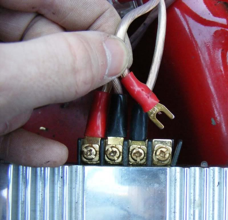
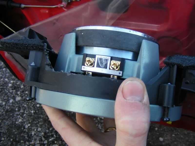
39. Right, at this stage we have RCA cables and power leads available for each amplifier so we might as well move on to the speakers themselves. The system I am using as an example has 6x9s in the rear, these are a typical speaker set up and the wiring is very straight forward - you basically have two wires, one positive and one negative that goes between the speaker and the amplifier's output.
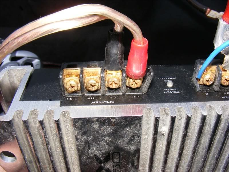
The first picture shows a typical 2 channel amplifier which has two sets of terminals for speakers to connect to. The only thing to note here is making sure the + on the amp matches a + on the speaker body (and vice versa with the - of course!). Make sure you have good solid connectors, gold plated is usually recommended for a good contact.
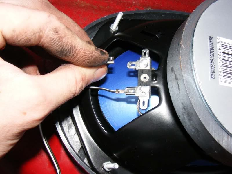
The second picture shows the spade connections on the speakers, note the '+' and '-' on the black plastic between the terminals. The speaker wire is normally supplied with the speakers but if in doubt use a larger gauge than you think you need, standard speakers don't need thick wire as shown but there are minimal side effect from having wire that is too thick.
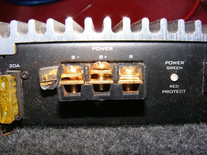
40. The power-related connections on an amplifier consist of three wires - the main positive feed, the ground return (the negative lead) and the wire to switch the amplifier on. The picture shows a standard labelling of terminals:
B+ This is the positive feed to the amp
B- This is the negative/earth/ground wire for the amp
R Also marked as 'Rem' for remote, this switches the amp on and off
41. The positive wire is the large gauge cable that runs from the distribution block to the amp as discussed previously so we will now move on to the ground connection. This is an often-overlooked connection and people think of the + wire as the important one - not true! The ground is as important as the supply for a circuit so you need to put just as much effort in here for the negative side of the circuit.
The ground wires should be made up as discussed earlier with good solid terminations used. Black wire is advised for ground connections to easily distinguish between live and ground connections (despite the fact the picture shows red!). Keep these as short as possible to avoid pickup problems (long = high resistance = volt drop when current passes = potential problem for noise)
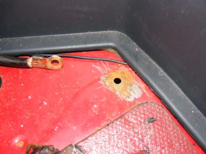
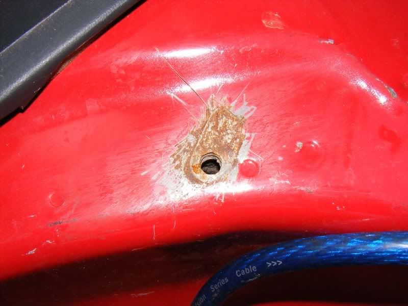
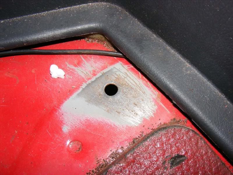
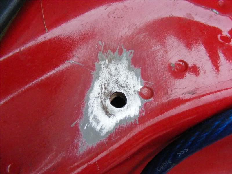
42. You need to find a suitable grounding point on the chassis, there are several potential spots in the Supra's boot, in my car I found someone had clearly been doing this before. The first two pictures show some rusty holes which look like they had been used for earthing an amplifier at some previous point. These were cleaned up with some sand paper to reveal bare metal which is very important to get a good ground connection (the car's chassis is directly linked to the battery's negative terminal). Obviously you will need to lift the carpet back to get to the metal underneath
Ideally you should ground each amplifier at a separate point but sometimes it may be necessary to share the ground return path. Make sure you terminate these connections well and ensure there is a solid connection to the chassis for current to flow.
43. The Supra's boot is a little bit tight on space so when installing a sub you may have difficulty with height of the box. For a newcomer to ICE I highly recommend you buy an off-the-shelf box for the sub you choose rather than fabricating your own. This is for acoustic reasons and you'll find a huge difference in speaker performance depending on the enclosure you use.
Note : There are typically two types of box used for a sub woofer, these are sealed and ported. They are exactly as you'd imagine, sealed is an airtight enclosure whereas ported has a tuned 'port' or hole for air to escape. The sub you buy will have details on whether it suits a ported or sealed enclosure but a sealed enclosure is quite normal. If you do start designing your own custom boxes then make sure you calculate the volume of air required for the box correctly - this is very important!
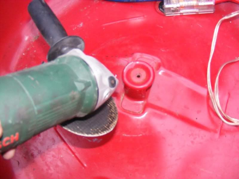
Assuming you have an off the shelf box and are short on space, the spare wheel well is an ideal place to gain some room (especially if, like me, you have no spare!). Obviously if you sacrifice the spare wheel you need to take other measures for puncture recovery i.e. a can of the 'fix a flat' style aerosol to limp you home.
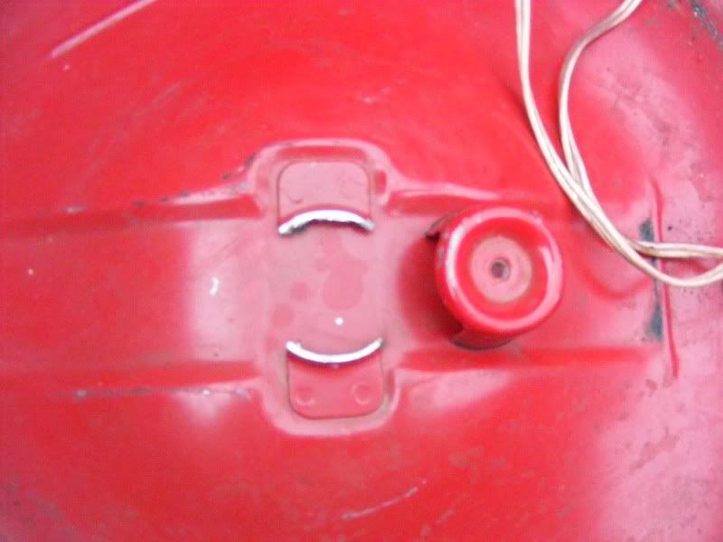
Remove the wheel and use an angle grinder to detach the mounting bracket.
Now you can either drop your box in or, if you're feeling adventurous, fabricate an enclosure to allow your sub to sit in the spare wheel well.
44. The final wire to connect for the power supply is the remote wire and then you can power the amp for the first time

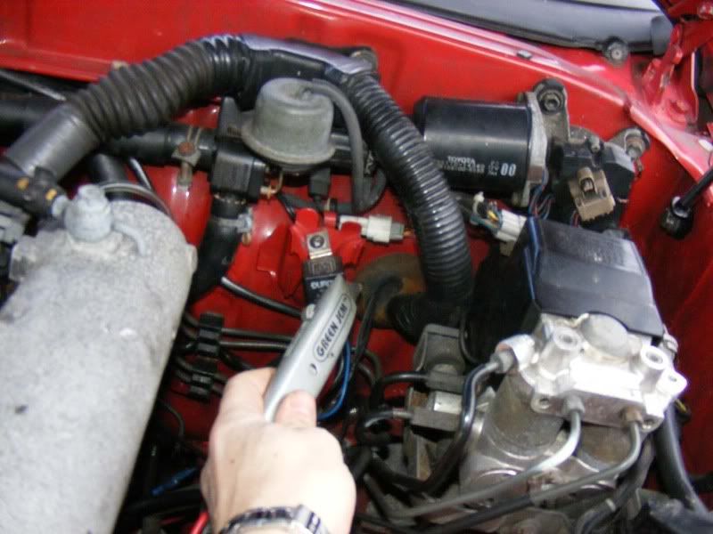
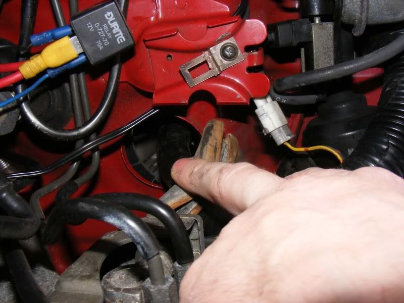
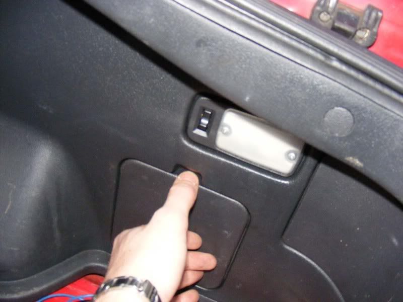
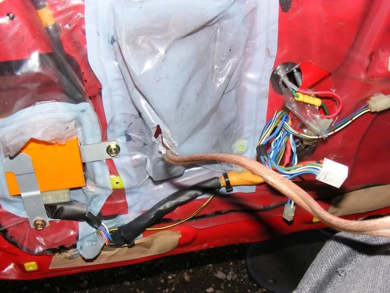
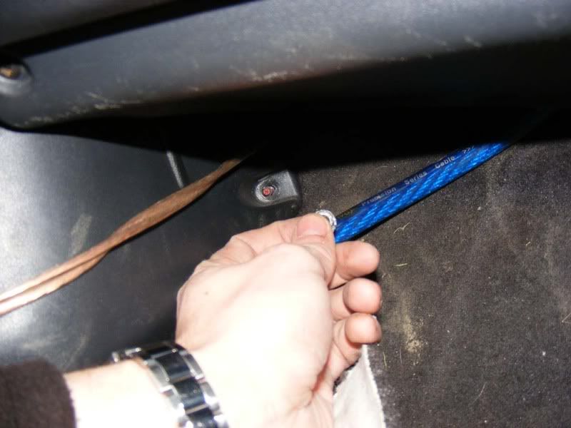
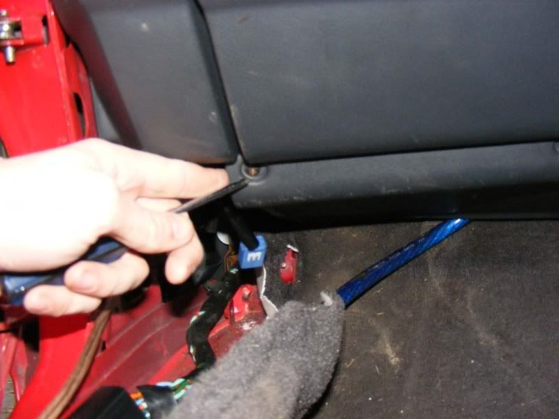
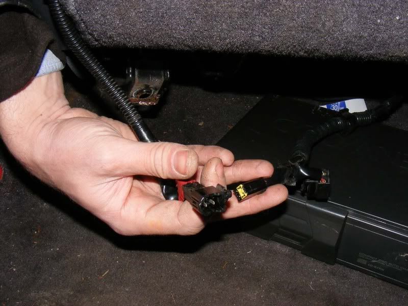
45. The remote wire is basically a low current wire which supplies +12 volts when you want to turn the amp on. This is a bit like a traditional relay where you have your beefy supply and return wires and then a small switcher wire which turns the device on. Typically your head unit will have a blue wire marked as 'rem' or 'remote' which outputs a +12 level when the head unit is turned on. Alternatively you can use a standard switch to the battery to allow you to manually turn the amplifier(s) on/off. For my install I decided to use the electric antenna's +12 volt feed to power the amps. Start by removing the cover in the boot
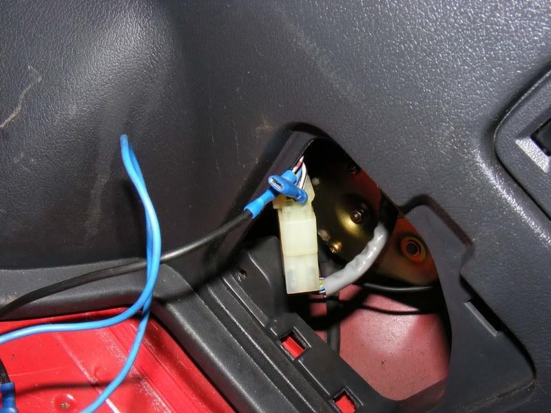
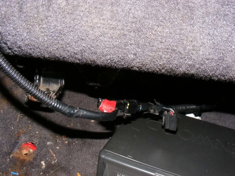
46. Now ease the wiring out and you'll find a connector for the antenna. Mine had already been meddled with as shown but take the bottom left hand corner's wire and splice into it with your 12 volt feed to the amps (use a voltmeter to check you have 12 volts when you switch the stereo on and 0 volts when you switch it off before you cut the wire!). To introduce your new wire either use spade clips or a block connector
47. Run this wire (use blue if you can, it's the standard colour for this) to your first amplifier. If you have multiple amps then you can piggyback the wires between each amp. First, cut the wire at an appropriate juncture so it reaches the first amplifier (allow a little slack too).
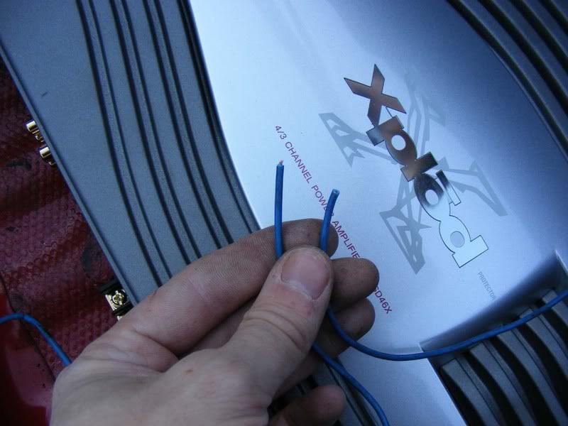
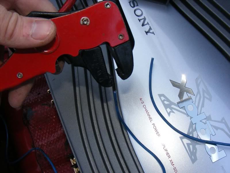
48. Now strip the ends - get some strippers like the ones shown from maplin etc and it will make life much easier
49. Twist the wires together to join them
50. Now fit it to the remote temrinal of the amp and you have the other end of the wire to run to the next amplifier in the system. this way, a single +12 volts from the antenna can supply all the amps. If you are running more than 2 or 3 amps then you should consider running a separate feed to a relay or directly form the battery via a switch because each amplifier will draw a small amount of current through this wire.
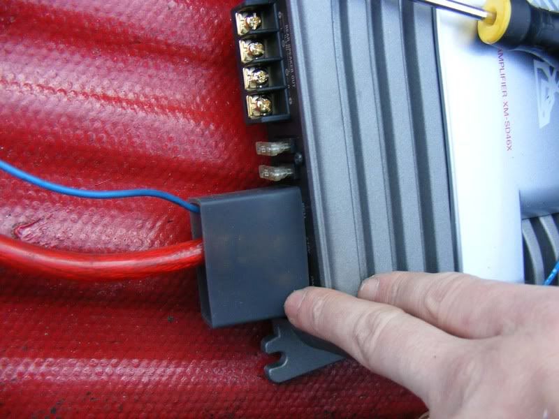
51. Ensure your + and - wires are not going to tough each other and fit any rubber surrounds or shields to protect them. My new Sony amplifier came with a big boot to cover the power connections as shown
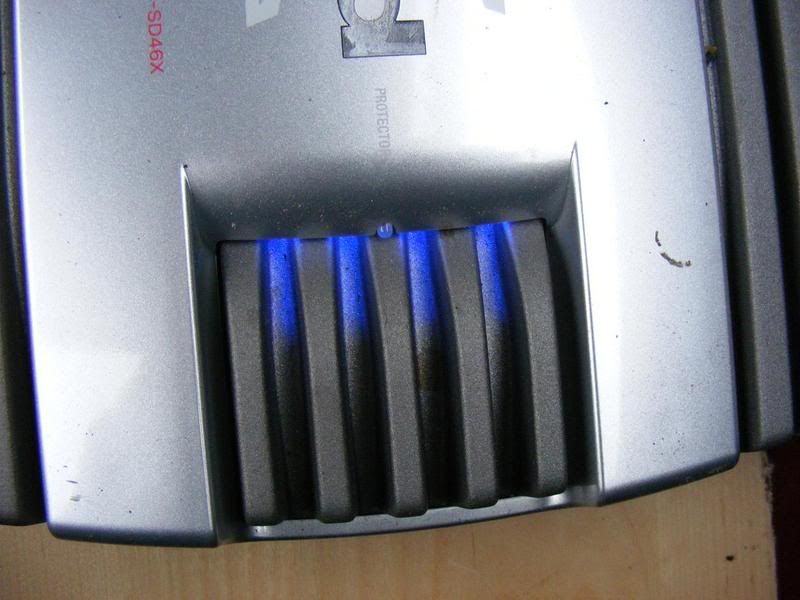
52. By now you have all the power supply wiring complete as well as the RCA leads to feed the sound in so you can think about fitting the fuse at the battery and distribution block. It is worth powering up the amplifier at this stage to make sure your supply, return and remote wires are correct (typically there's an LED on the amp to tell you if it is on or in a failsafe state). Once you've proved the power supply is correct move on to some sounds.
53. OK all inputs are checked and OK so we'll finally do the remaining output wires to the speakers in the front. I usually do this in the boot for ease of access then relocate them once everything is working roughly. As mentioned earlier, over spec the cable and you don't have to use the bell wire that comes with the speakers (although normally it IS adequate). Strip about 1/4" off the wire
54. Slide the sheath over the wire which will protect the connector from shorting on adjacent wires
55. Trim the wire as necessary to suit the connector
56. Slide the connector over the bare wires (which should be twisted together)
57. Now crimp the connector on. You can use mole grips and hurt your hands whilst creating a poor connection or buy this tool (again Maplin or similar for about £10) and make a much better install.
58. Tidy the connector and trim any wires that escaped the connector
59. Now slide the sheath up over the bare metal of the connector for protection (and it looks neat)
60. Finally, fit the connector to the amp noting the polarity - ensure the + on the amp matches that of the speaker. Notice on the second picture that it goes + - - + so don't get confused here, this is quite common
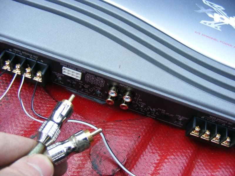
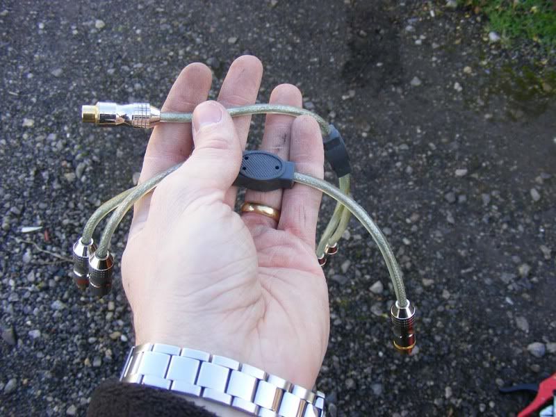
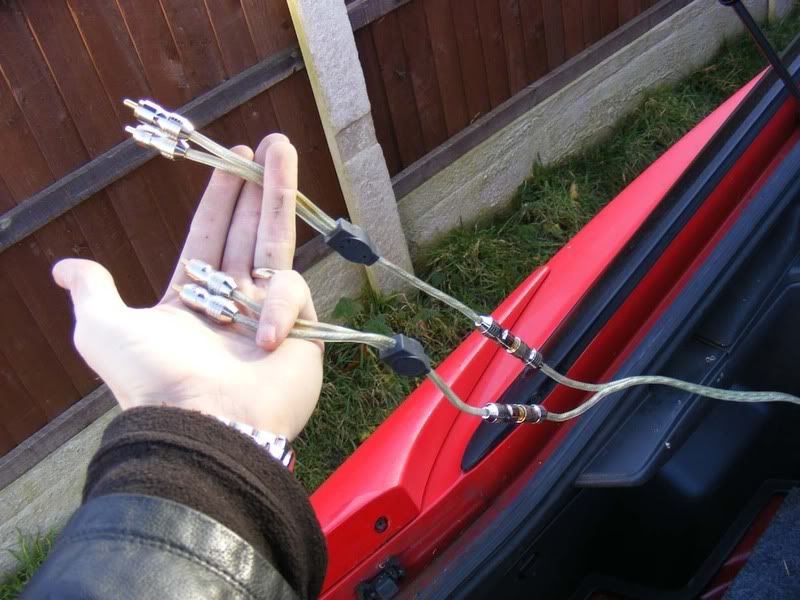
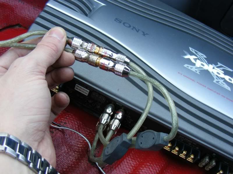
61. On a 4 channel amp you will need two RCA inputs (first picture), usually a front and rear (or sub). In my case I was using three amps and required four sets of RCA leads (one for sub, one for the amp powering the two front speakers and two sets for the two sets of 6x9s in the rear). To handle this you can get splitters which make one RCA feed into two (see second picture). Plug your feed from the stereo into these splitters and you suddenly have your two RCA feeds to the amp (picture 3/4)
62. Now you can do a full system test, I suggest you power up each amp one at a time and each speaker one at a time as well for fault finding, in my case I did:
1. Powered all 3 amps with no speakers
2. Powered amp for the sub alone and tested the sub
3. Just powered the amp for the front speakers and fitted each speaker individually before fitting both together
4. Powered the amp for the 6x9s only and tested each of the 4 speakers one at a time before fitting all 4
5. Full test with all three amps and all 7 speakers
Now it's wired you have the fun bit, making parcel shelves, enclosures, custom door pillars, burying wires etc! At this stage you are about half way through an install but you've done all the wiring parts and the rest is about tidying up. Test the system operates correctly and then the tweaking can start.
Here's the way I set up my amps (once the speakers are all in place of course!):
1. Turn the stereo down to the minimum volume you will listen to and remove any additional bass or sound effects from the head unit. You want raw sound output with no equaliser interference at this stage. Start the engine and put your ear to each speaker - if you have electrical noise and your wires are properly routed then check for ground loops etc. You can get supressors which reduce the noise but they can only reduce it rather than eliminate it so you're better off finding the route cause
2. Put the head unit to about 80-90% volume and then power each amp individually, setting the gain to an appropriate value i.e. the highest you can without distortion of the sound. Note that you may need to go for a drive to test this because sticking your face next to the speaker will give you a very distorted idea of what the max volume is
3. Once all amps are individually configured, turn them all on and tweak to balance out the sound
You will have to start finding rattling bits of trim at this stage, especially with a sub - everything will be rattling, number plates, rear light covers, plastic trim etc. You can use sound deadening sponge or just remove most bits and pieces but this is usually an ongoing saga!
63. Once you've got everything installed and set up you need to start tidying up the wiring. The power and RCA cables strewn across the seats should be totally hidden from view and you need the wires from the amplifiers to the front speakers to be routed down the car too. Generally speakin power supply wires and speaker wires should be kept apart to reduce interference - that whining noise you get when the engine is running is due to interference and you need to try and avoid this. I run the power leads down the nearside of the car because the grommet and battery are on this side and then have the speaker wires (both RCA leads from the head unit and the small speaker wires from the amplifier) down the offside.
You are going to start routing a few wires between panels and behind the dash now so a word of warning - every time you place a wire double check it's not going to get crushed, burned, caught up in a motor/lever and otherwise damaged. Things like switches to turn fans on and move vents around can cause wires to get tangled if you aren't careful so use some common sense when routing cabling - as a general rule try and follow the stock loom for a safe path through the vehicle.
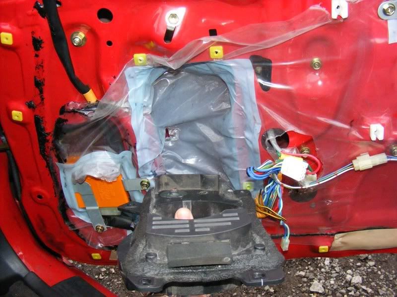
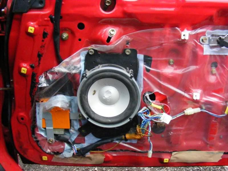
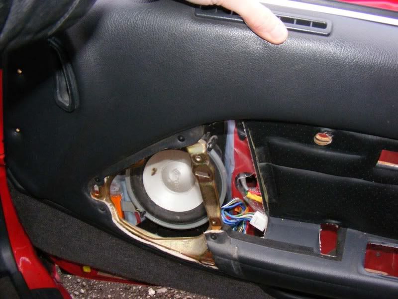
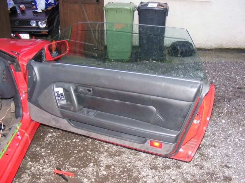
OK we'll start by fitting the door speakers. Follow the guide to removing a door card then test fit your speaker in the standard housing (you'll obviously need to remove the screws holding the stock speaker in and disconnect the wires to it!
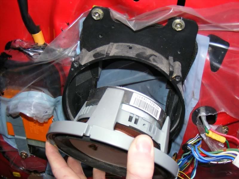
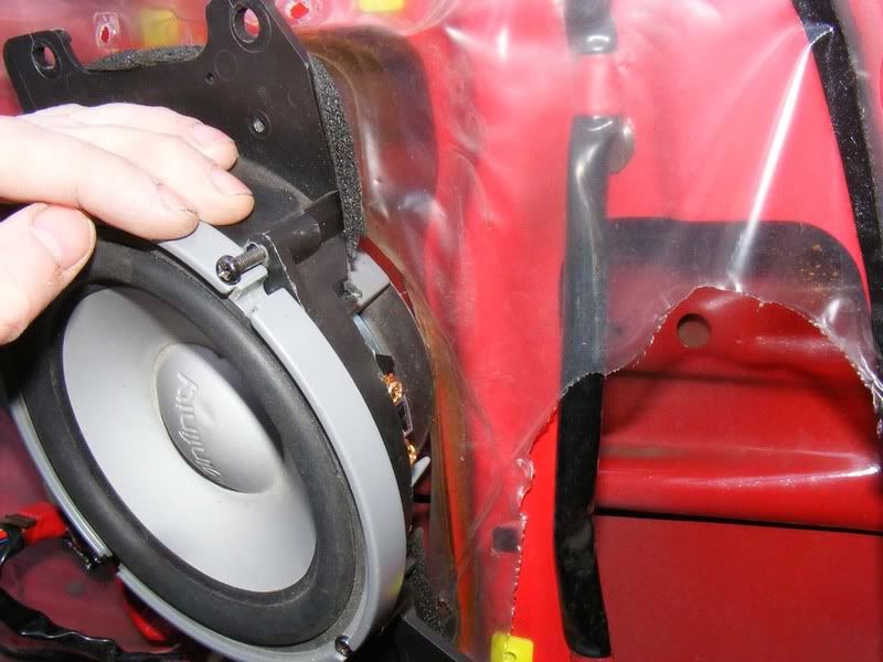
64. If you've gone for a large speaker such as the 6" kappa perfect's you will find it fouls on the plastic cowl as shown
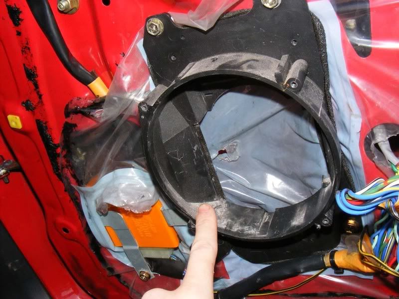
65. Remove the four gold bolts holding the surround in place (10mm or a philips screwdriver)
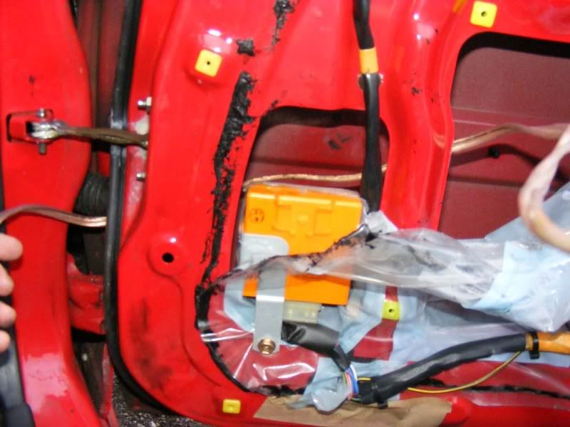
66. Once removed you'll see the plsatic covering for the inside of the door is all that's left, try to leave this in tact whilst working inside the door
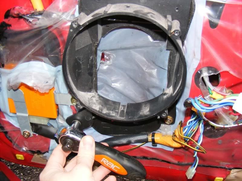
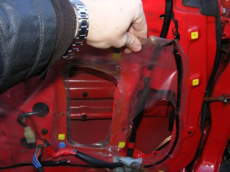
67. Pull back the plastic to gain access to the inside of the door
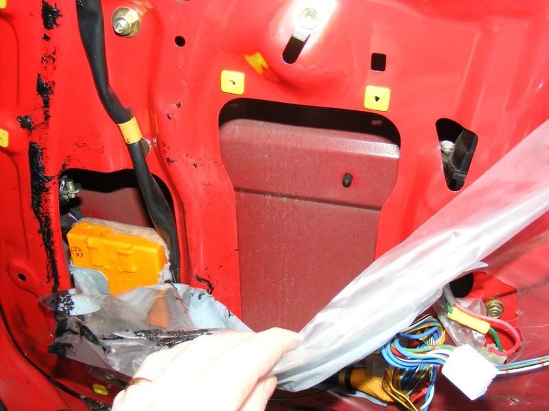
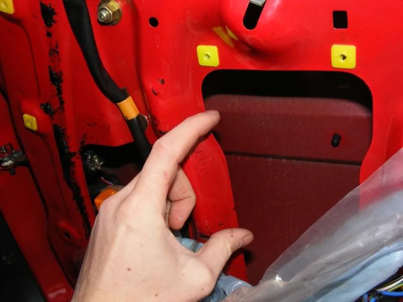
68. Check your speaker doesn't hit this piece of metalwork, mine was clear on the driver's side (not on the passenger side though as shown later)
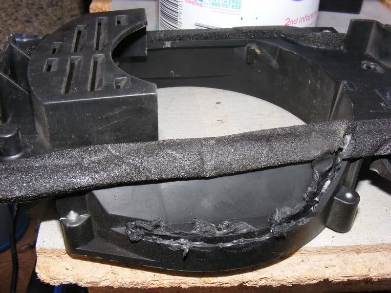
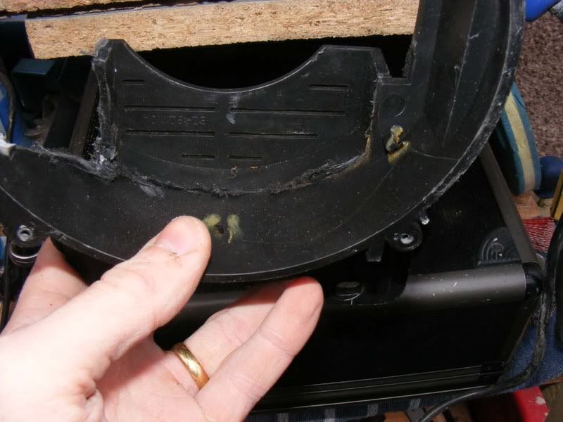
69. Now it's time to remove the piece of plastic causing us trouble so get a Dremel style tool out and cut away the problem area
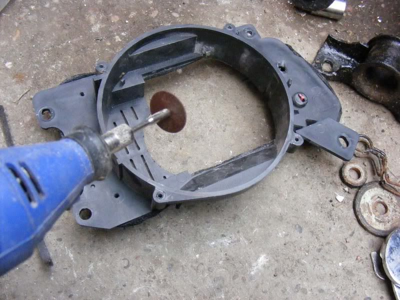
70. This doesn't have to be particularly neat but try not to destroy the enclosure completely! I cut close to the edge as shown on the first picture and then ran up the side through the sponge. I than ran a cut along the inside of the enclosure as shown in the second picture. And finally broke away the two pieces and neatened up with a file as shown in the third picture
71. Once modified, attach the speaker to the plastic using the 4 mounting screws (they may not match up so you can make an adaptor plate if you need it or just use a couple of the screws which I did). Note that you will need access to the speaker terminals so make sure they face the cut out you made earlier as shown in the second picture
72. Test the door card will fit over the speaker before you go any further (it should do)
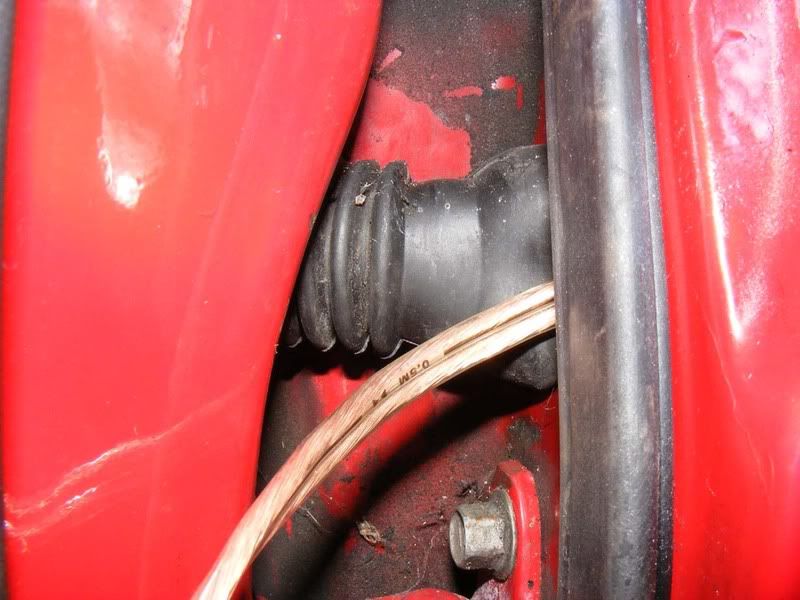
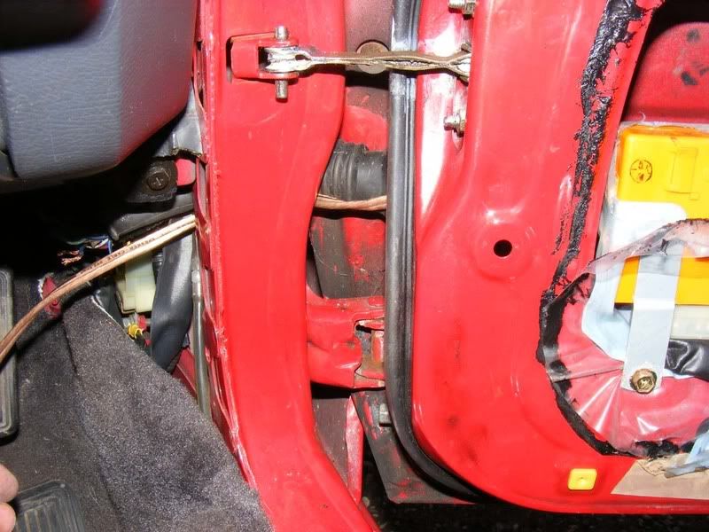
73. Now you need to route some wiring from the amplifier to the speaker which is a little tricky. You can modify and re-use the stock wires which makes life easier but if you want better wire or have rubbish stock wiring (my install met both criteria) then you might want to consider this. Pull the plastic door cover down even further and thread from the inside of the door through the side of the grommet to the gap between the door and chassis as shown. This is not easy but persist and you'll manage it, careful help with a screwdriver to move the grommet around may be required but don't split it!
Ideally you'd go through the grommet like the stock wiring loom but it's more difficult to do and takes time so I tend to go around the outside as shown in the second picture
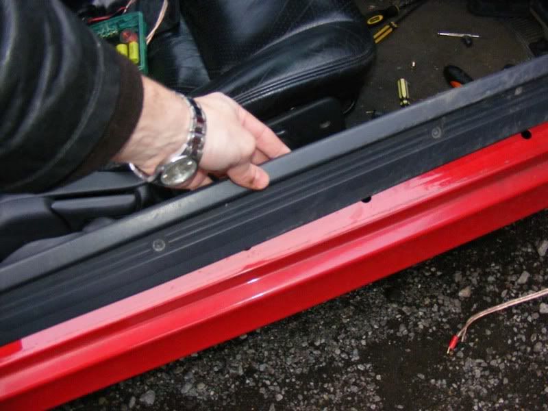
74. Once you are through the grommet you need to go into the car itself. start by removing the 4 screws that hold the sill cover in place
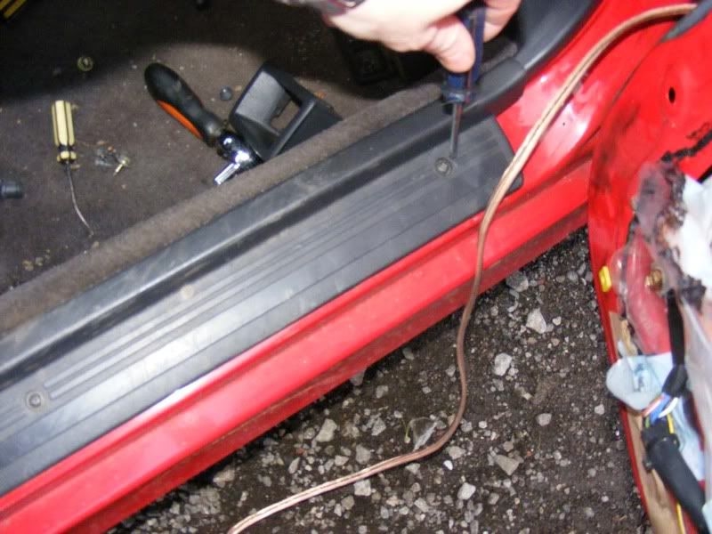
75. Then clip it out, it should just pull away with a few clicks
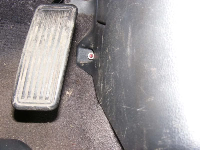
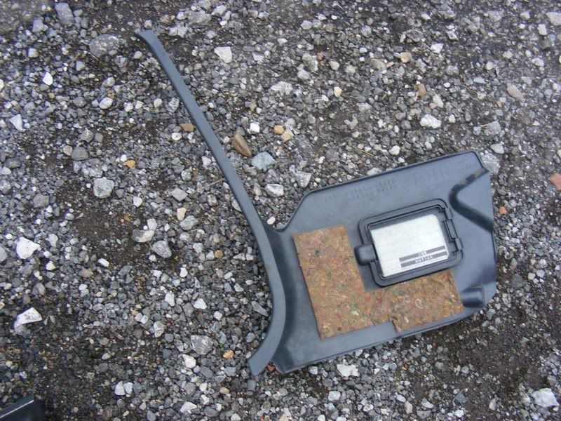
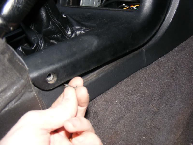
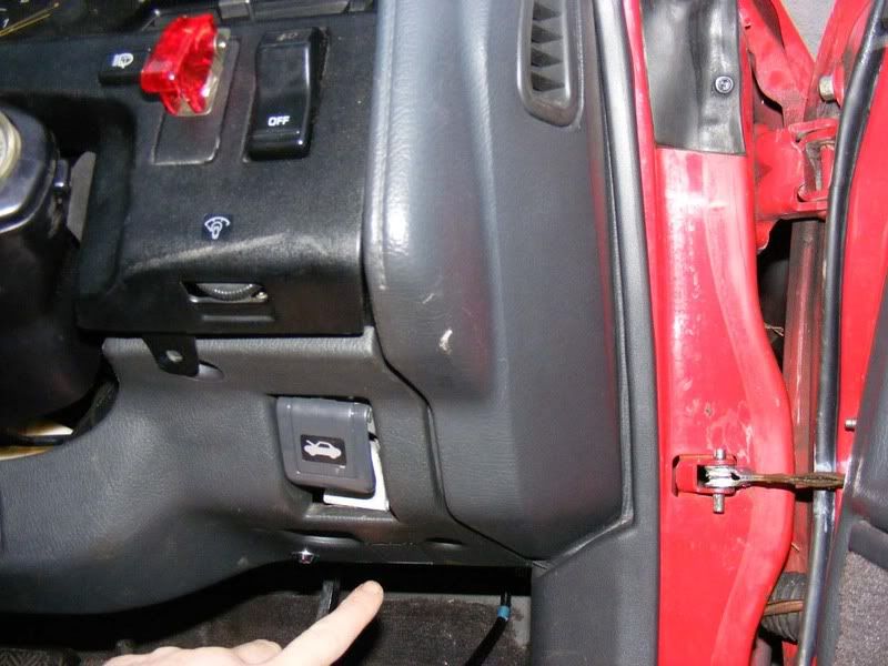
76. Now get the single 10mm nut which holds the piece of plastic trim around the fusebox in place, just next to the accelerator pedal
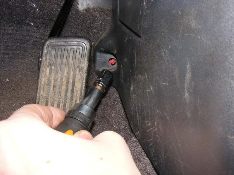
77. Now ease the piece of trim away from the top and slide it out towards the back of the car, there should be a little resistance and some wriggling will be required but it should pull out easily
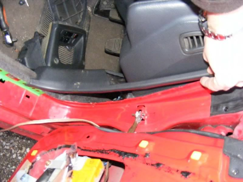
78. Now you can complete the feeding of the wire through the door in the other side of the grommet and pull it into the car
79. Ensure the speaker wires go through the plastic sheet before you connect them
80. Connect the two wires to the speaker, as always note the polarity of the wires. You want to have the positive terminal of the speaker connectored to the positive of the amp for all speakers (if you mix and match then you can have speakers moving out of phase with each other which is not good), I use the wire with the stripe as negative for all mine
81. Now refit the plastic surround, top first - it has some padding to hook into the door as shown for sound deadening
82. Refit the plastic trim of the driver's kick panel, careful to route the wire appropriately before you bolt it down
83. Now connect the wire to your crossover box or rub it to your amplifier. For me it was to a crossover as shown, again the only thing to remember is the polarity of the wires
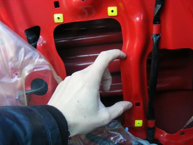
84. On the passenger side there is a slight complication in the fact that the metalwork on the door is slightly different. If you try and fit 6" speakers they foul the door as shown
85. Remove the plastic door cover to get good access to the metalwork
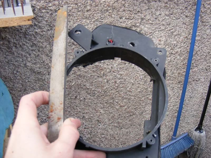
86. Mark out the area to cut off
87. Then use a metal cutting disc to remove the offending material. It's very thin and easy to get through, at a push you could use a hacksaw but it would take much longer and even a novice could learn to use an angle grinder on this piece. Don't go too far into the metal because you reduce strength, just enough to fit the speaker in place. Use ear defenders and goggles and make sure you don't have anything that doesn't like sparks around e.g. fuel. Also, remove the speaker from the scene because it will catch all the metal filings due to the big magnet on it
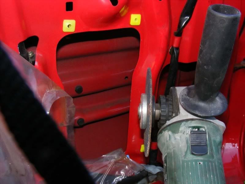
88. You should end up with something like this
89. The only other point to mention for the passenger side is that when removing the kick panel you have one additional screw to undo which is the one for the plastic cover underneath the glovebox. It's the far left screw only and hooks into the plastic trim as shown
90. Follow the steps in the door card guide to refit and once you've finished you should have a stock look with a much improved sound to the system
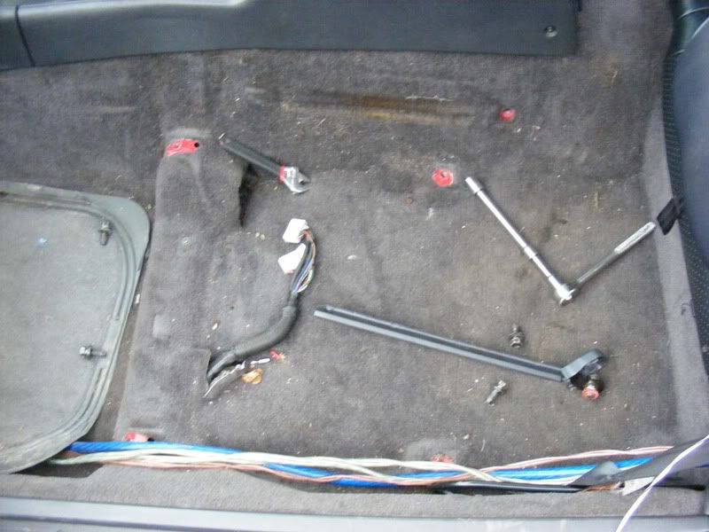
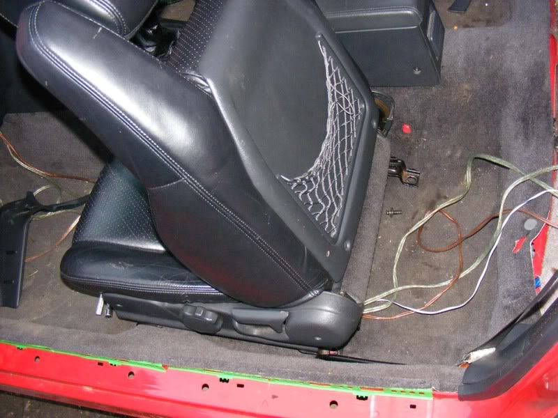
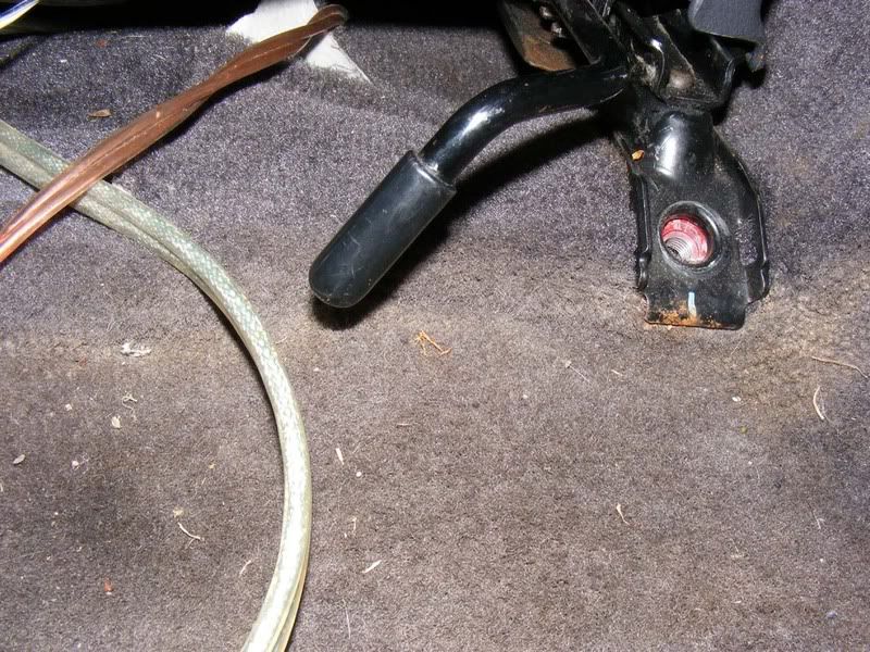
91. Your next stage is burying all the wires and hiding crossover boxes. Start on the passenger side (slightly easier than drivers side), slide the seat forwards and slacken the 2 14mm bolts shown (remove the plastic covers by pulling them by hand if you have them fitted)
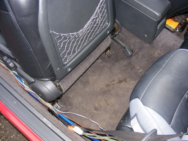
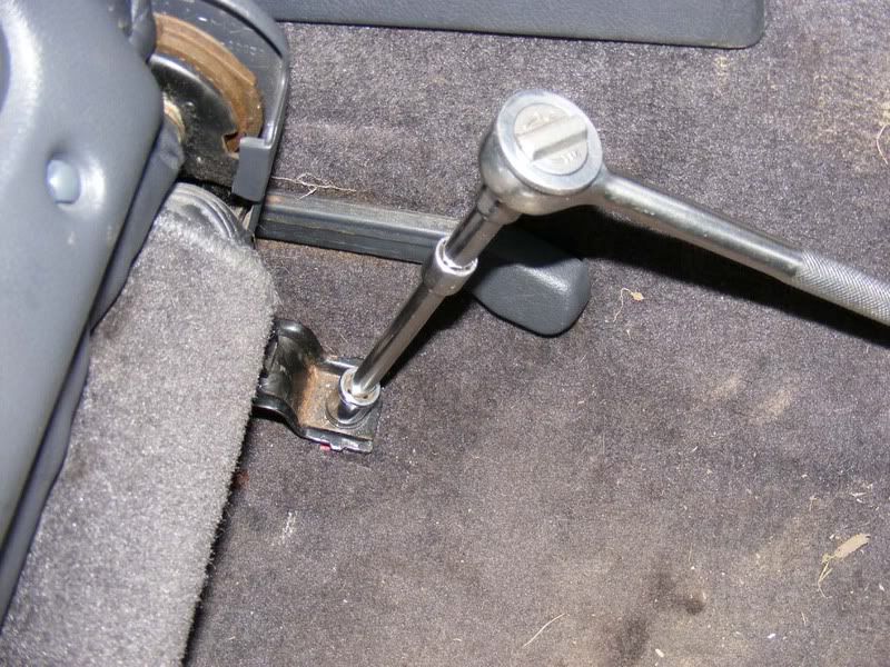
92. Slide the seat back and remove the 2 bolts at the front, again these are 14mm
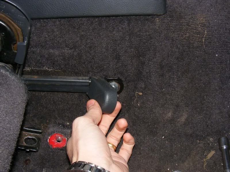
93. Now pull back the cap as shown and remove the final 14mm bolt
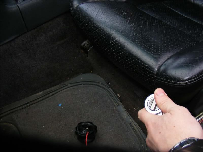
94. You can now pull the seat from the car, there should be no resistance at all so if there is stop and check you haven't caught a wire
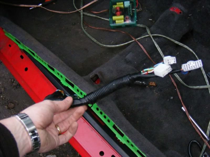
95. You're left with a view of the carpet and possibly the stock amp wiring, if you're ditching this (which I recommend) then just trace the wires back to the head unit and remove as shown in the pictures
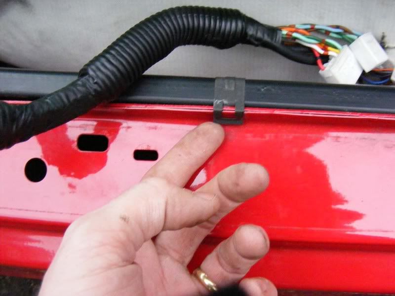
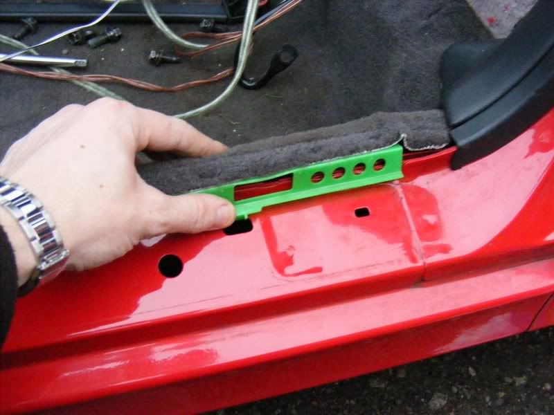
96. The sill cover needs to be removed now, 4 philips screws and then clip it off
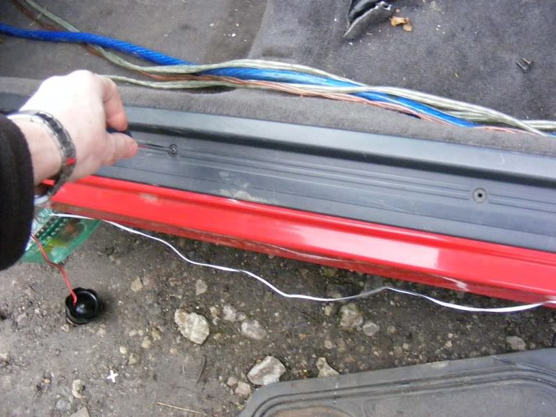
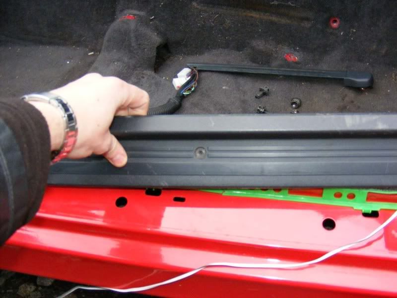
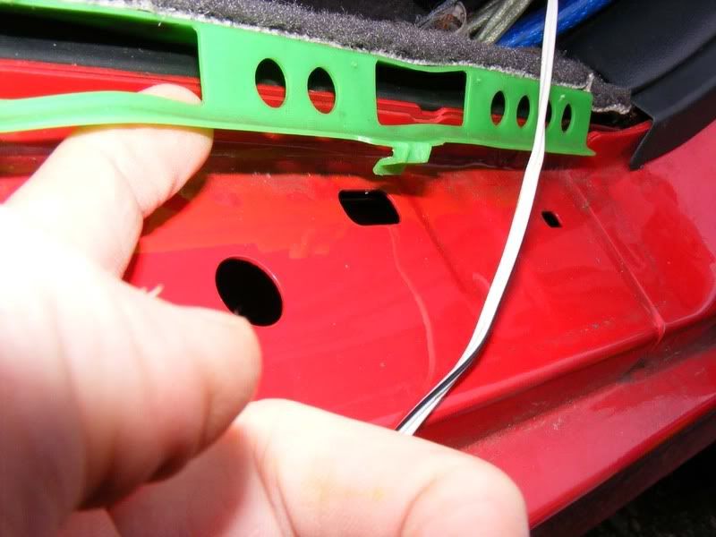
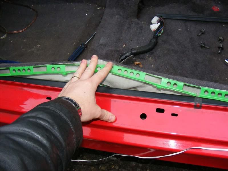
97. The green plastic retainer can now be unclipped along the sill by pulling it towards the door and lifting up
98. When you've finished you should be able to pull the carpet back freely as shown
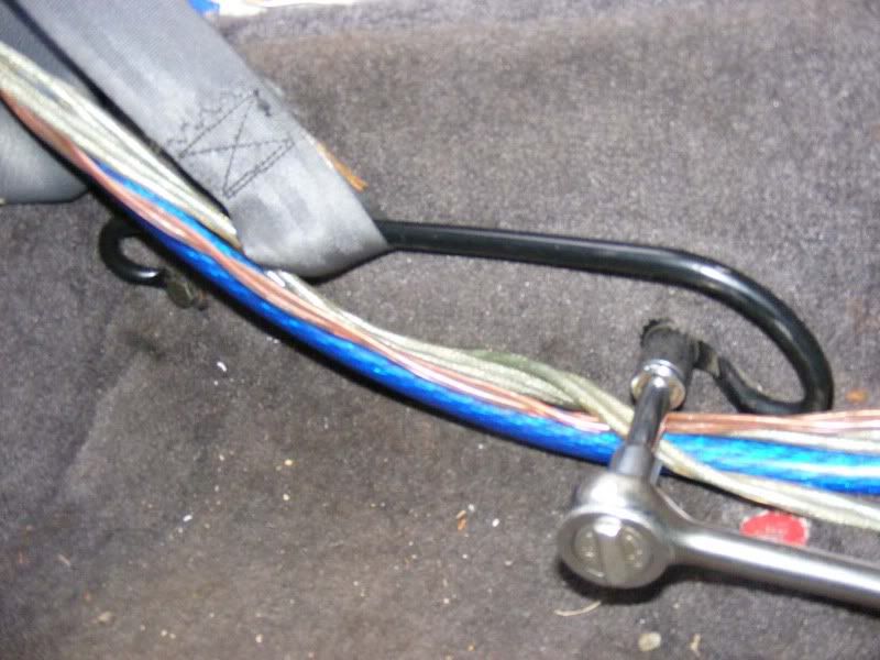
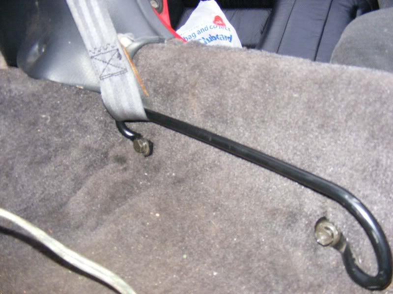
99. Now remove the two 14mm bolts holding the seat belt bracket in place
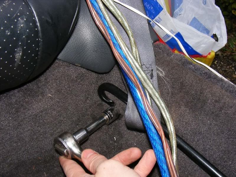
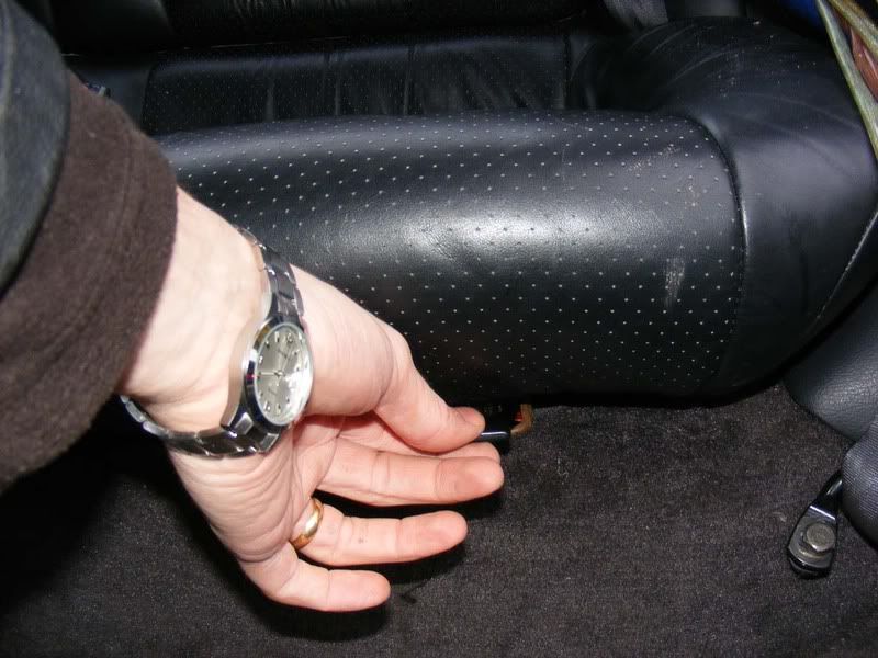
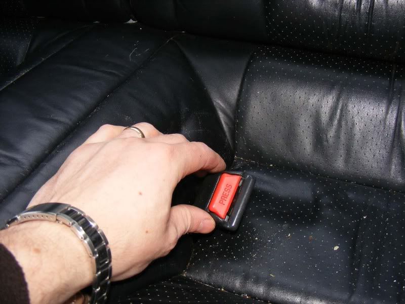
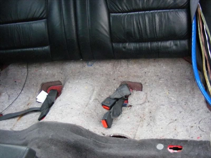
100. The back seats need to come out for access underneath, there are two clips to pull - pull them up towards the ceiling and then slide them forward, they may be quite tight.
101. Slide the seat belts down through the holes as shown
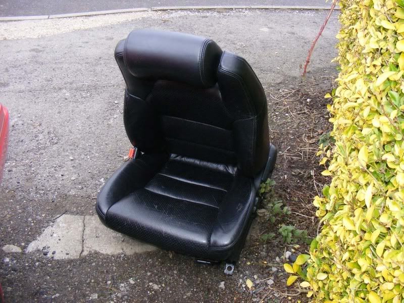
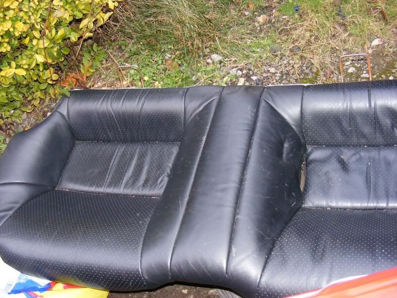
102. Remove the seats and place them outside the car
103. You now have good access to the edge of the carpet and underside of the seats as shown
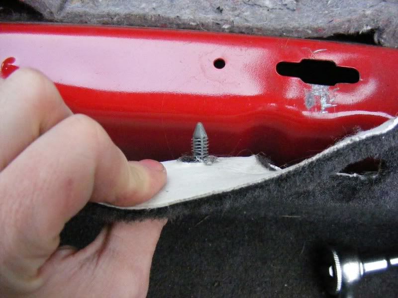
104. Remove the plastic retainers as shown by pulling them straight up, try not to pull at an angle or they bite harder. It will need a bit of a tug - there should be one either side
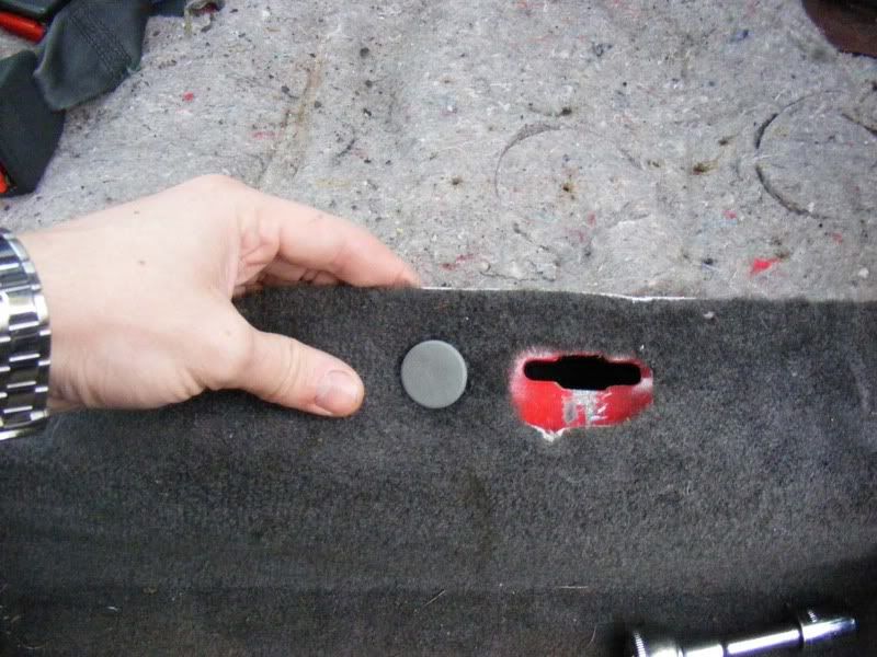
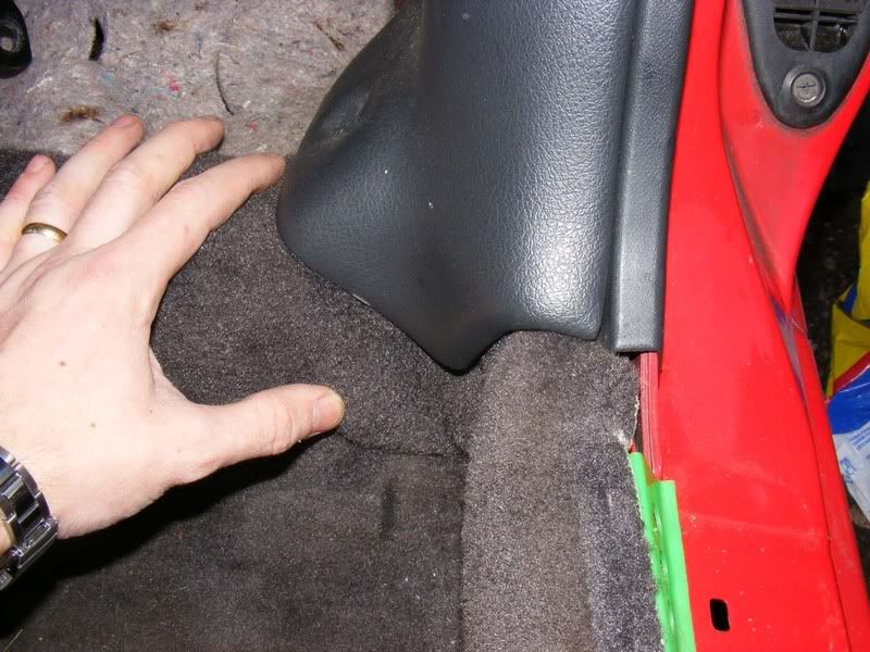
105. Head for the corner where the passenger's feet lie and wriggle the carpet down so it is clear of the trim
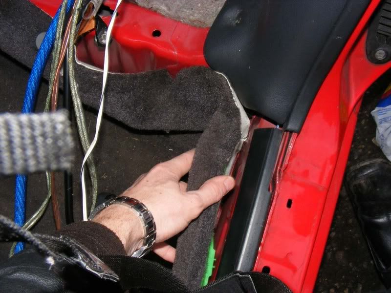
106. Now you should be able to lift the carpet completely and have access down the length of the car for routing cables
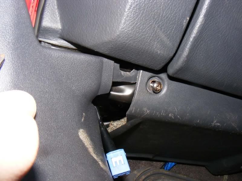
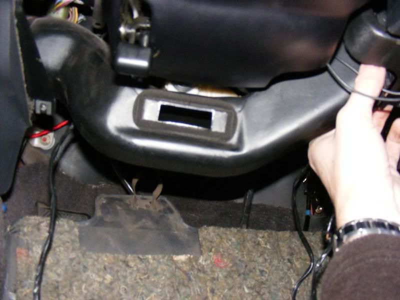
107. The only area you need to free up now is in the front passenger footwell, remove the 10mm nut shown
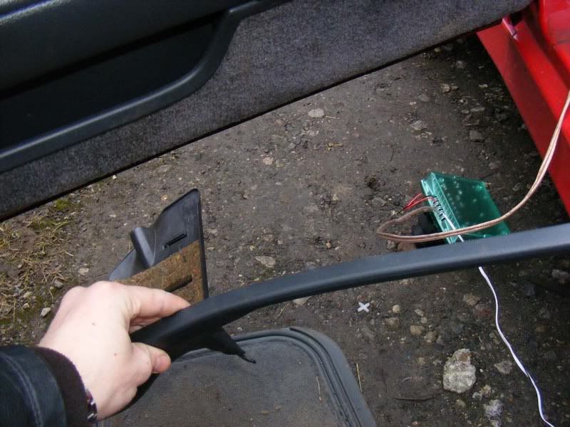
108. For this side you need to remove the left hand screw as shown
109. Now remove the trim by sliding it out
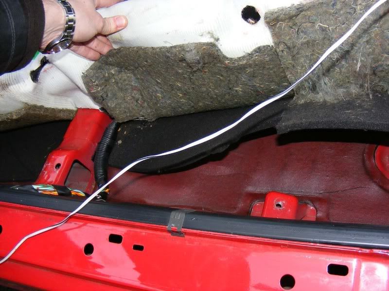
110. Pull the carpet up at the front and slide your main power cable underneath, note we are only routing power cables down this side not the RCA or speaker signal wires
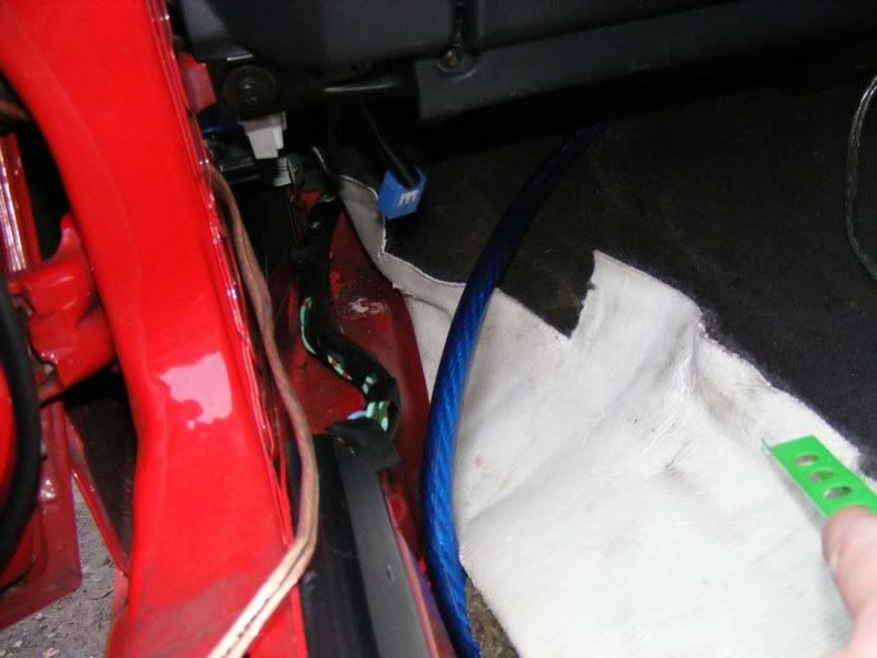
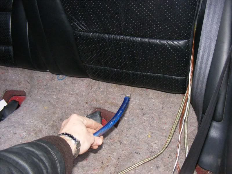
111. Route the cable along the underside of where the seat will be mounted (down the middle of the seat well clear of the mounting points to avoid any problems trapping the wire) and feed the wire up under the back seats as shown
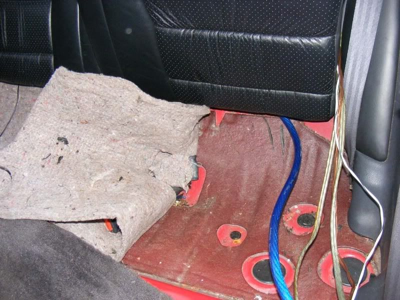
112. Ensure the wire is underneath all sound deadening and padding material as shown
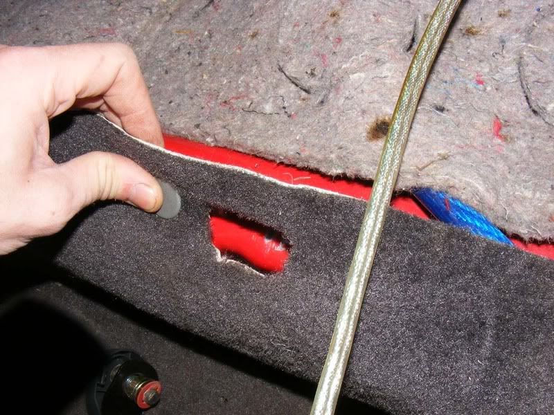
113. Clip the carpet back into place, again make sure your power lead isn't too near the point where the rear seats clip into place
114. Refit the carpet you removed from the corner and push it flat
115. Clip the green plastic clips back in to hold the carpet down
116. Fit the seat belt retainer bar back in place with the two 14mm bolts, ensure they are tight
117. Put the passenger seat back in the car
118. Line up the 4 mounting holes and fit the stabaliser bar with its 14mm bolts
119. Loosely fit all 4 bolts to make sure the seat is squarely lined up then tighten them down
120. Onto the driver's side now, we will route all our speaker cables down this side. I will show the differences for this side, most of it is identical to the passenger side, first you have to slide the seat about by hand obviously because it isn't spring loaded like the passenger side
121. You have an electronic seat for the driver's side so remove the connector as shown, this just pulls apart
122. The rest is the same as the passenger side (note when you refit the seat, there is a dowel on the front left bracket that must drop into place, if the carpet gets in the way you'll struggle to refit so just a head's up), you'll need access to under the steering column for cable routing. Also you need the head unit out so remove the screws holding the centre console in place
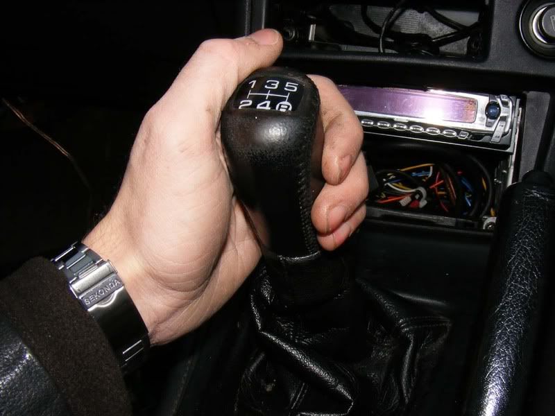
123. Remove the gear stick by untwisting it (I think this is all covered in the turbo timer guide in more detail if you get stuck)
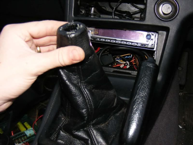
124. Pull the gaitor up over the stick
125. Unclip the three top spring clips by pulling forward, there should be little force required
126. Unplug the multi plug to the cigarette lighter (squeeze and separate) then unclip the hazards, rear demister and fog light multiplugs by pressing the locking plastic tab then pulling clear
127. Remove the surround
128. Now remove the cage holding the stereo in place, 4 philips screws
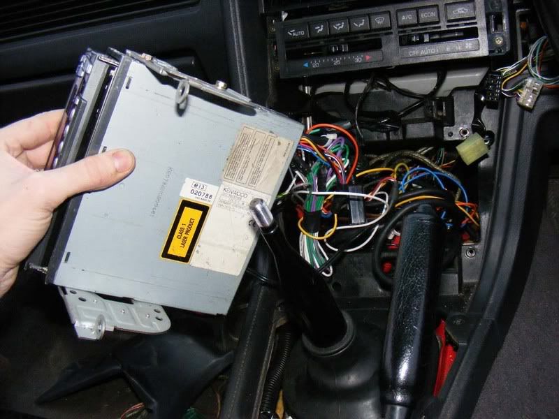
129. Remove the head unit and as much wiring as you can
130. Now remove all the philips screws under the steering column
131. Don't forget the two under the bonnet release
132. Unclip the air duct for the heater by pulling down with moderate force
133. Now you have good access to all the wiring, be aware of the movement on all the pedals and avoid routing wires near them
134. Run your RCA leads under the carpet as you did with the power wire and feed them up to the back of the head unit. If you have a crossover box then pop this behind the cover for the steering column on the right hand side behind the ducting you removed. Once you've done this, refit all the bits you just removed and test the RCA cables/speaker connections are working
On the passenger side for a crossover box you can route the cables up the back of the glovebox (you'll need to remove the 3 lower screws and cover to feed the cables/crossover in place) as shown
Hopefully that covers everything you need to install an amp and speakers including burying all the wiring and making a totally stock look. Some time will be required in setting up the system but you should find it's significantly better than any standard system.
Fitting an amplifier isn't something that should just be relegated to those who like cruising round town centres in the small hours disturbing the locals. Most head units have a relatively low power output e.g. around 15 watts whereas most speakers on the market will start at approximately 50 watts. When you introduce high power components and subwoofers you can easily reach hundreds of watts required to drive them properly.
As standard your car may be fitted with an amplifier but this is prone to trouble and it's generally recommended to bypass it when it fails and fit an aftermarket unit to boost performance. The job of an amplifier is basically to take an input signal (the stereo's signal to a speaker) and increase the power output by effectively injecting some power before sending it to the final destination e.g. performance speakers.
If you read around the subject of amp/speaker selection you'll often find a recommendation to buy a decent expensive unit rather than a cheaper alternative, this is actually sound advice. Myself, I was always tempted by having more and more bits in the system so soon ended up with half a dozen amps and a few subs with several sets of speakers throughout - the appeal of quantity over quality for the same price won me over! As time goes by you realise that a better quality sound is achieved by a few select components set up correctly so pick wisely!
There's a lot of misinformation out there, especially when it comes to speakers. It's important that your amp matches the speaker's output which is measured in watts. When you go to buy a speaker (or amplifier) it will claim huge power figures but in reality they are significantly smaller (Usually at leats half and up to 10 times smaller!). Basically ignore anything that says peak power, you are interested in the nominal value or RMS wattage which is the real world power rating of the speaker. You need to tot up all the RMS values of the speakers, add a small margin and then select your amp(s) accordingly.
Recommendation
As a general guide I'd suggest:
1. Spend your money on the front speakers, buy something special with at least 50 watts RMS, preferably around 100 for a loud but good sound. I really like infinity kappa perfect 6.1s, they have a crossover (special box of electrics that sorts out frequencies and forward to the appropriate speaker), tweeters (for the high frequency sound) as well as the mid/bass unit (the general sound).
2. For the rears I'd go for any 6x9s (oval speakers that roughly measure 6 inch by 9 inch), the quality here is less important and is more a filler in my opinion. I'd look for something with at least 50 watts RMS once again and you can fit two sets if you really want some volume (I did on this install, two sets of £20 from Argos and they sound just fine)
3. Subs are something you can easily get carried away with but for most installs a single 10 or 12 inch sub will provide ample performance, aim for 200-300 watts RMS for a decent sound. Note that you need substantially more power for a sub than for other speakers to produce the high energy needed to move the cone. I do quite like the Sony Xplod subs which are cheap but most branded subs will perform well e.g. MTX, JBL etc.
4. Assuming 100 watts RMS to each front speaker, 50 watts RMS to four 6x9s and 300 watts to a sub you have 100x2 + 50x4 + 300 = 700 watts RMS. I'd be looking for at least an 800 watt amp so it's not being pushed to the limits. For my install I'm using two Phoenix Gold (very good) QX2350 amplifiers which can supply the 100 watts RMS to each of the front speakers and one will be 'bridged' (two channels joined together) to power the sub with ~300 watts. Finally I bought a Sony XM-SD46X amplifier which can give me 4x60 watts RMS to my 6x9s which is great at £50 for a brand new amplifier!
Channels
The next thing to introduce is the number of 'channels' which is the number of speakers an amplifier can drive e.g. a 4 channel amplifier can drive 4 separate speakers. To complicate this you can use bridges, sometimes confusingly referred to as crossovers because you cross the wires over, where you combine one or more channels to power fewer speakers but with more power e.g. a 2/3/4 channel amplifier could be used to drive 4 speakers at a given value, for example 100 watts. Alternatively you can run in '3 channel' mode where you drive two of the speakers at 100 watts then combine the other two channels into one more powerful channel at, say, 150 watts. Then you can go further still and run 2 channels, both bridged to provide 2x150 watts.
OK so we know you need to check the RMS rating of speakers, the wattage of the amplifier must be big enough to cater for this and you understand that the number of channels is important with regards to selection of an amplifier.
This is a bit of an overview of a lot of topics because you can get really bogged down with the detail - if you start thinking about dual voice coil subs and monoblocks with class d efficiency then you probably don't need a basic guide for fitting an amplifier anyway! Anyway, on with the next bit - ohms!
Ohms
Ohms are a measure of resistance (the amount a component resists the flow of electricity). For in car entertainment (ICE) it is referring to impedence which is like resistance but varying with frequency. You don't need to worry too much about the physics but suffice to say the speaker and amplifier's impedence should be matched i.e. a 4 ohm speaker should be powered by a 4 ohm amplifier. You should consider this when buying both speakers and amplifiers.
Typical values are 2 ohm, 4 ohm and 8 ohm with 4 ohm being the most common. Amplifiers are usually stable at 4 ohms and often 2 or 8 ohms. Generally to start with look for 4 ohm speakers and a 4 ohm stable amplififer.
The lower the impedence (number of ohms), the more power is produced as a general rule. A 2 ohm capable amp is the minimum load supported, this is per channel in stereo mode. If you bridge channels the stability is the sum of each channel e.g. a 2-ohm stable 2 channel amp can be bridged into a single 4-ohm mono channel
If you have a 2-ohm stable amp, you can utilise the extra power by wiring your speakers in parallel (wire two sets of 4 ohm speakers to the same + and - terminals on the amp). Due to the extra power being produced the amp will get a little hotter but a 2-ohm stable amp can disperse this heat properly.
Conversely you can wire speakers in series to increase the load an amp sees. This makes the amp run cooler but produces less power so is rarely used. If you want to do this you simply run from your + amplifier terminal to the + speaker terminal then from the - speaker terminal to another speaker's + terminal. This second speaker then runs the - terminal back to the amplifier - terminal in a daisy chain fashion
Wiring
Supply wiring to an amplifier is of great importance, if you do this badly then you risk damage to yourself and the components (very easy to blow amplifiers by doing silly things). Selecting the correct 'gauge' or thickness of wire is also important. The lower the gauge (often called AWG after American wire gauge) the thicker the cable and the more current it flows. For a really large system you could go as low as 0 gauge cable but typically a 4 gauge or 8 gauge cable will suffice. To determine the cable size you work out the number of amps it requires to pass and then look up the appropriate cable thickness.
This is a rough guide I shamelessly lifted:
0 gauge|334 amps
1 gauge|265 amps
2 gauge|210 amps
3 gauge|167 amps
4 gauge|132 amps
5 gauge|105 amps
6 gauge|83.4 amps
7 gauge|66.2 amps
8 gauge|52.5 amps
9 gauge|41.7 amps
10 gauge|33.1 amps
11 gauge|26.3 amps
12 gauge|20.84 amps
13 gauge|16.54 amps
14 gauge|13.13 amps
15 gauge|10.42 amps
16 gauge|8.27 amps
17 gauge|6.56 amps
18 gauge|5.21 amps
19 gauge|4.13 amps
20 gauge|3.28 amps
21 gauge|2.60 amps
Current and power
Right, now we've mentioned another thing - amps (amperes/amps are a measure of current). This one is also very important and is directly linked to the watts (power) we mentioned earlier. Your car stereo is running off a battery, this battery will sit at around 12 volts when the engine's not running and then rise to about 14.8 volts when the alternator is doing its job. I'm going to assume you only use the stereo when the car's engine is running (or you need to look into secondary batteries and split charging systems) and we'll assume a voltage of 14 volts to be conservative.
Right so we have watts, amps and volts how are they related? Watts / volts = amps and we know volts = 14. So we use the total number of watts in a system, say 700 watts RMS like we used earlier then divide by the voltage (14) which gives us 700/14 = 50 amps. We therefore need cable capable of carrying at least 50 amps of current to supply this (as always you'd add an overhead so get a cable capable of carrying at least 60 amps to be safe nad probably more like 100).
If you intend to expand the system then add plenty of overhead in your wiring and over spec your amps so you can add more speakers etc as necessary. Also keep in mind that amplifiers are not 100% efficient and people recommend up to double the current requirements for a given wattage e.g. out 50 amps would be increased to 100 amps to genuinely supply the 700 watts we require! Read the technical spec of your amplifier to find out more
Amp classes
The electronics of an amplifier determines its 'class'. They are loosely defined as follows:
Class A - High quality sound but high heat production, not used in automotive applications normally (often a class A advertised amp is actually class AB)
Class AB - Reasonably efficient, low distortion and high reliability, your normal car amp
Class D - Even higher efficiency, less heat and less current draw than AB but more distortion. Perfect for subs where you won't detect the distortion
Class T - Hybrid of AB and class D amps
Filters
Certain speakers are better at reproducing certain frequencies e.g. a sub will produce low frequencies well whereas a tweeter (the tiny speakers) are best suited to high frequencies. You can filter the sound to only let certain frequencies reach your speaker using low pass and high pass filters. A low pass filter will only pass low frequency sound to the connected speaker so should be used for a sub woofer. A high pass filter allows high frequency sound to reach the speaker so would be used for a tweeter. This is amplifier specific, some have it, some don't - it should come with instructions to help you set the frequency of this filtering but I thought I should mention what it is to be complete. Below is a picture of what you may get (note the switch with off and hpf (high pass filter) for one channel and lpf (low pass filter), off, hpf for the other channel.
One point here is that low frequency sounds are less directional than high frequency sounds, what this means is that the direction you face your sub woofer is of little importance (people often prefer them facing the rear of the car). With tweeters, however, the position is of great importance and makes a big difference ot the sound. The recommendation is often to have them right next to your ear or directly facing it with one speaker either side at equal distances from your head (or as close as you can). The kick panels are one favourite as well as the door cards.
Signals
Getting the output of your head unit to the amplifier can range from very easy to slightly perplexing. The options are:
1. Your stereo has RCA outputs in which case you're laughing and simply run the RCA lead from stereo to amplifier, this is the easiest and therefor imho best route and what I have done in this guide
2. The head unit supplies preamp outputs, run these straight to the amp or a patch cord (see below)
3. You have a bog standard factory stereo with no feeds for an amplifier, what do you do? Well, purchase an amp with speaker level inputs (high level input in the pictures below). You can then wire the stock speaker wires to the amp and use these signals to drive the amplifier.
If you don't have speaker level inputs or preamp inputs on the amplifier you can get an RCA patch lead with line converter which will allow you to convert the signal from the standard speaker wire to an RCA feed to an amp.
Important!
Your electrical system is over spec'd as are most/all cars i.e. there's a headroom available between what the alternator kicks out and what the car actually uses. IIRC the Supra has about 20-30 amps 'free' which is enough for about 300-450 watts of RMS power. If you start trying to drawy 2000 watts then you can expect to kill the alternator, trust me I have done .. twice. If you are going to build a massive install then you really need to consider having a second alternator or a rewired standard one with a larger output e.g. over 100 amps.
When the bass kicks in and your headlights dim then you know your system is really struggling, people will tell you to fit a power cap (capacitor) to handle this but I am not a fan of this. Basically the capacitor stores a bit of extra energy and when your alternator/battery is unable to deliver power fast enough the capacitor steps up. Unfortunately the capacitor is then discharged and will become another draw on the system to prepare for the next burst from a sub.
One recommended approach is to have a secondary battery for the stereo which will only take charge when the primary battery (your normal battery) is fully charged. This is achieved by a 'split charging' system which monitors the status of the normal battery and then allows the alternator to start charging the second battery when appropriate. The big benefits to this approach is that you should never find yourself with a flat bettery due to the stereo drawing too much power and also the alternator should not be over worked.
If you do decide to go donw the split charging route then I recommend you look into Optima or similar deep cycle batteries. Even if you don't go for the second battery it is worth considering a deep cycle battery as your primary cell. The main reason you would go for a deep cycle battery is that you can discharge it far more than a standard (lead acid) cell without it becoming irreperably damaged. As I'm sure a lot of you will know, once a standard battery has been left for a long time and discharged too much it will never recover no matter how long you put it on charge. The deep cycle technology allows for vast amounts of the battery's energy to be depleted whilst still recovering to full capacity when it gets charged up.
So, recommendations for power supply are
1. Get a high power alternator
2. Get an Optima deep cycle battery
3. Use a split charging system
The alternative is that you just run off the standard alternator but I warn you to expect problems with multiple amps and subs
1. This is rapidly turning into an article rather than a guide so we'll start some practical work and throw in more theory as we go! I'm going to show how to fit a system with several amps and one 12 inch sub + front and rear speakers. For my install I'm going to use 0 gauge cable to allow for massive performance and plenty of future expansion (plus I had some zero gauge kicking around!). I don't anticipate any of you needing cable this large and 4 gauge is probably as big as most will go but the wiring work is identical.
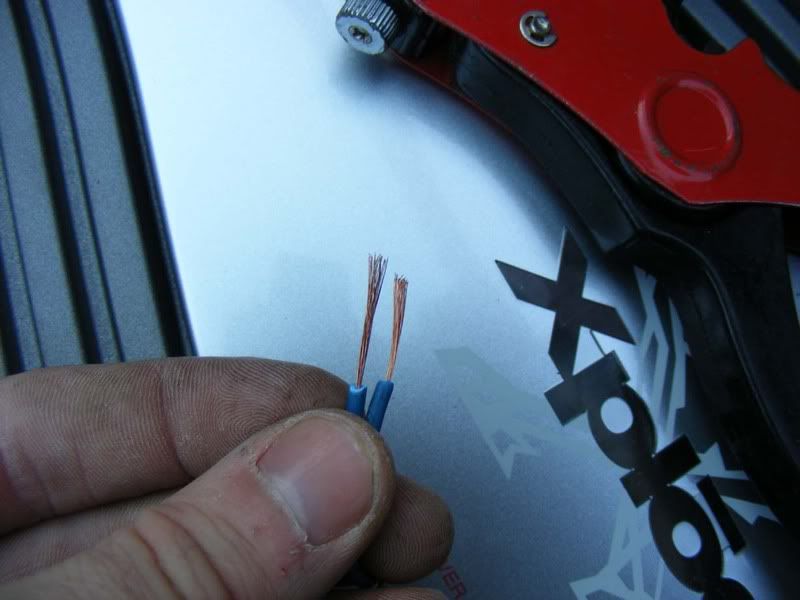
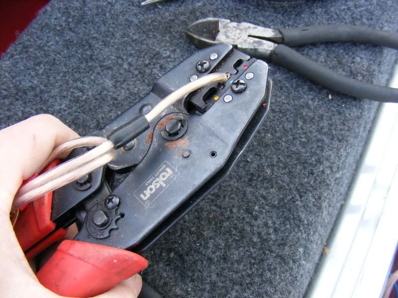
Here's a picture of some scrappy looking cable, this is not what you want to be using for your connections so we'll start with proper terminations.
2. Use a pair of scissors for smaller wire but in my case a hacksaw to cut back to a clean wire
3. Now run a stanley knife blade around the outside of the sheath. Careful not to cut the core of the wire inside - you'll get the hang of it after doing a couple. Ideally you cut just deep enough so that when you flex the outer insulating material it splits and reveals the metal beneath
4. Lever the newly separated outer core off the wire
5. Now you've exposed the core, if necessary twist it two prevent any rogue wires sticking out, mine was pre-twisted
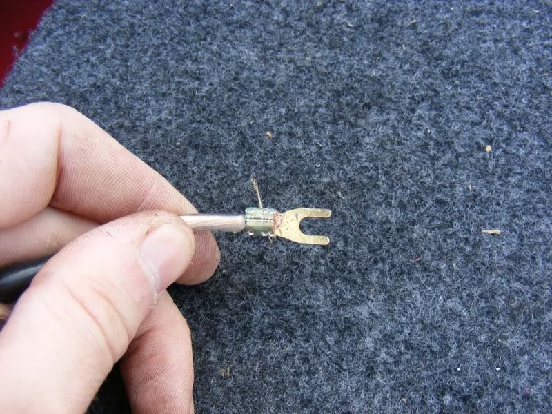
6. Now grab yourself some suitable connectors, these usually come with an amp wiring kit which I highly recommend for beginners. If you get the gold connectors then they are usually pretty expensive but make good connections and importantly are easy to shape and crimp. Expect to pay extra for them though, the cheapest I usually get them for is £1 each
7. Where necessary, open up the connector so you can fit the wire in, this can be done with mole grips or gentle work with a hammer and flatblade screwdriver (only for steel ones, mole grips will be fine on gold)
8. Fit the connector around the cable
9. Now clamp securely around the cable
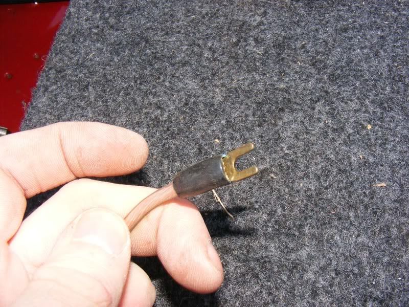
10. For best results, solder the cable to the connector too
11. Fuses - very very important! Do not skimp on fuses at any point in the system, I guarantee at some stage they WILL svae your behind! Drop a cable orshort a screwdriver to an amp body etc and suddenly you have a problem - unless you fit a fuse that is. First things first, as soon as you've left the battery within 12-18 inches fit a fuse capable of supplying the whole system. In my case I had a 150 amp fuse which is able to supply 150 (amps) x 14 (volts) = 2100 watts RMS!
Always fuse just after the battery then run your cable to the amp and fuse for each amplifier you supply. To start with you need a cable which goes from the battery to a fuse block (amp wiring kits normally have an inline fuse provided), for my install I had an external high ampage fuse so require 2 terminations as documented in the first 10 steps. You'll end up with something that looks like this
12. The cable from the battery terminal then goes to a fuse box (shown on the right hand side of the battery in the picture). Then the ring terminals are used to join the wire from the battery (I'm holding it in the picture) to the main power supply that will run through the car. On the left hand side of the battery is the fuse I am using which slides into the holder and bolts down with 2 14mm nuts. I suggest you don't fit any of the fuses until you have routed all the wiring to avoid accidents during installation
13. You need to consider where your amp(s) will be located e.g. under seats if you can fit them or in the boot. When mounting the amplifier ensure you leave it in a place where it is in 'free air' i.e. there's nothing directly on top of it because the amplifier uses the housing as a heat sink to cool itself down. Don't mount an amp upside down or the heat goes out the cooling fins then straight back towards the amp
To reduce the chance of noise pickup don't mount the amp onto the car's metalwork, either go on the carpet or make a simple MDF platform to mount it to (this is preferable so it doesn't fly around the boot!). 'Ground loops' are to be avoided which is where there are multiple ground paths for one amp.
If you do get noise problems then you can do things like checking the resistance between the RCA sheild and the head unit ground and if necessary tie them together as well as various other checks. Grounding is often the key to pickup. Also try unplugging the antenna and see if that cures it, if so you can get an antenna isolator. A properly installed system will usually avoid interference and 'alternator whine' though.
In my opinion the only suitable place in a Supra is really the boot so it's a case of running a power cable from the battery at the front of the car all the way down to the boot. Thankfully there's a perfect grommet available which is the main harness to the ECU.
Locate the rubber grommet on the firewall as shown and make a slit in it using a stanley knife
Note: If you wish to run the power cable down the other side of the car, there is a grommet for the clutch hose which is suitable
14. Now it's time to work inside the car, whip your mat out and get on your knees
15. Remove the 3 screws holding the cover underneath the glove box
16. Slide the cover out of the way
17. There are two black metal brackets that hold the glove box in place, undo the two philips screws that hold these in place
18. Now release the glovebox catch and you should be free to remove it
19. Slide the glovebox out sideways as shown
20. Now you need to remove the catch mechanism that is held in by a further 2 screws and there are 2 more screws at either side of the catch
21. The flexible plastic can be pulled out on one side and eased gently down
22. Don't forget to twist and remove the internal light for the glove box
23. Remove the plastic screw at the back of the cover then remove completely
24. You now have access to the ECU, ABS ECU etc. Thread your wire to follow the routing of the big loom as shown
25. Remove the grommet completely (a flatblade screwdriver can be carefully use to do this - it is stretchy but don't stab it too much or you will pierce it)
26. Once you've pulled the grommet up the loom you'll be able to see in the hole and hopefully locate your power cable you fed through (you can obviously do this the other way if you prefer so thread the cable into the car from outside
27. Pull the wire through, thread it through your slit in the grommet and ensure you have enough wire in the engine bay to reach your fuse at the battery terminal. Note you will want to route the wire in the engine bay along the bulkhead away from any moving parts and the radiator where it could be melted.
28. Once you've finished pulling the wire through, replace the grommet using a screwdriver again as shown. Start by hooking in the bottom of the grommet and side closest to the wing which is awkward to get to. Then you can use the screwdriver to force in the side you have best access to. The second picture shows the refitted grommet
29. While we've got some good access we should start to route some of the speaker wires which run from the head unit (the stereo itself) to the amplifier. These wires are typically 'phono-style' leads which are known as RCA leads (after the Radio Corporation of America who designed them). These leads run striaght from the head unit and provide a quality signal to the amplifier. You should ensure that any head unit you buy has at least one set of RCA outputs (connections for RCA leads to fit). Typically you will have up to three RCA outputs, the front speakers, the rear speakers and a specific subowofer output. Also, your amplifier should have RCA connections although there are alternatives if you have an amp without RCA connections but that's a separate topic.
The best RCA leads will be 'oxygen free' and once again, the more you spend the better the lead. In my experience the mechanical quality of the more expensive leads is significantly better but I can't tell any sound quality differences. People known as 'audiophiles' get very anal about all the connections and cable qualities but to you and me it makes such a minor difference it's not worth spending hundreds of pounds on RCA leads - £10 should buy a more than adequate set but again, these are usually supplied with the amp wiring kit.
Note you should read on and decide which side of the car the RCA leads will fit before doing this
30. Feed the RCA leads up from under the glove box to the area behind the head unit (see the guide for fitting a stereo for details on removing the head unit so you have access here)
31. Once you've oruted your RCA cables and power wire out you can start putting the glovebox back together - note I have the zero gauge cable and 3 sets of RCA leads (front, rear and sub) to route.
32. Pop your glovebox light back in and twist to secure
33. Fit the plastic expander from the back of the cover (removed in step 23) then re-fit the screw
34. Now pop the catch back on and the two screws either end of it
35. Clip the glovebox into the catch and push the black brackets back over their dowels before fitting the 2 philips screws
36. Finally slide the lower cover back in place and put the 3 screws back in
37. For now, simply route the cables out of the way so we can get them to the boot - by the time you finish none of this should be visible but initially just run the cbales over the seats to the amps.
38. When running multiple amps (which is quite normal) or if you plan to upgrade to another amp in the future, I suggest you jump straight in with a distribution block as shown in the picture. These basically take a single feed from the battery (which is your thickest power cable that supplies all the amps) then splits the supply off through a fused link to each of the individual amps that normally have smaller power lines. In my case I drop from my single 0 gauge feed to 3 lots of 4 gauge feeds (again, this is very large and I expect most installs to take a single 4 gauge feed to several 8 gauge supplies).
The benefit of a distribution block is that if you have a problem on 1 amp it just pops the fuse for that amplifier without stopping the whole system. This leads to easy fault diagnosis and repair. Further to this you have expandability and can add further amplifiers at a later date which you may decide to do if you get the audio bug.
Fuse ratings should be caculated for each amp in a similar manner to your big fuse at the battery i.e. amp draw in watts / 14 volts = ampag of fuse. In our 700 watt system example we could have two amplifiers where one supplies 200 watts and one supplies 500 watts. This would require a 200/14 amp fuse and 500/14 amp fuse i.e. 14 amp and 35 amp fuse at a minimum. From this you always give a safety margin so I'd suggest a 30 amp and 50 amp fuse as a minimum.
39. Right, at this stage we have RCA cables and power leads available for each amplifier so we might as well move on to the speakers themselves. The system I am using as an example has 6x9s in the rear, these are a typical speaker set up and the wiring is very straight forward - you basically have two wires, one positive and one negative that goes between the speaker and the amplifier's output.
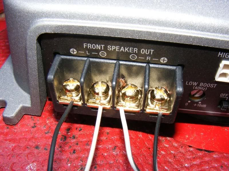
The first picture shows a typical 2 channel amplifier which has two sets of terminals for speakers to connect to. The only thing to note here is making sure the + on the amp matches a + on the speaker body (and vice versa with the - of course!). Make sure you have good solid connectors, gold plated is usually recommended for a good contact.
The second picture shows the spade connections on the speakers, note the '+' and '-' on the black plastic between the terminals. The speaker wire is normally supplied with the speakers but if in doubt use a larger gauge than you think you need, standard speakers don't need thick wire as shown but there are minimal side effect from having wire that is too thick.
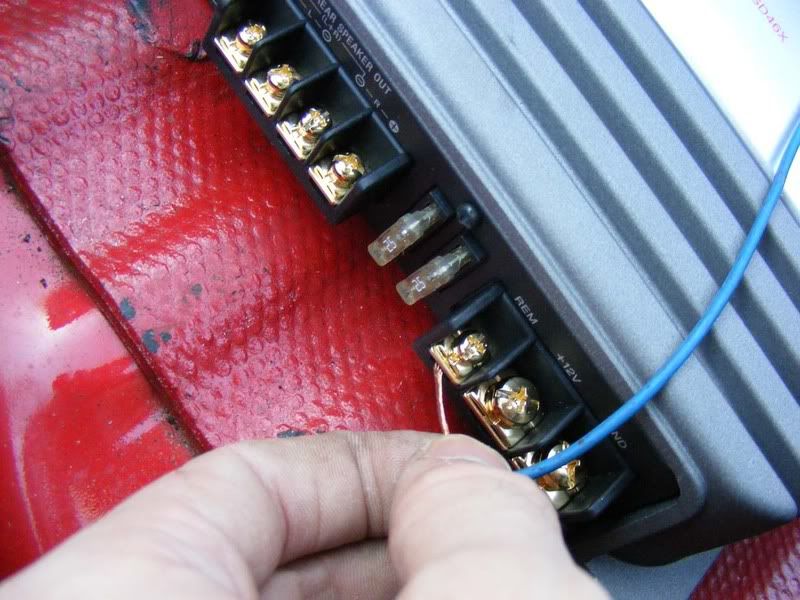
40. The power-related connections on an amplifier consist of three wires - the main positive feed, the ground return (the negative lead) and the wire to switch the amplifier on. The picture shows a standard labelling of terminals:
B+ This is the positive feed to the amp
B- This is the negative/earth/ground wire for the amp
R Also marked as 'Rem' for remote, this switches the amp on and off
41. The positive wire is the large gauge cable that runs from the distribution block to the amp as discussed previously so we will now move on to the ground connection. This is an often-overlooked connection and people think of the + wire as the important one - not true! The ground is as important as the supply for a circuit so you need to put just as much effort in here for the negative side of the circuit.
The ground wires should be made up as discussed earlier with good solid terminations used. Black wire is advised for ground connections to easily distinguish between live and ground connections (despite the fact the picture shows red!). Keep these as short as possible to avoid pickup problems (long = high resistance = volt drop when current passes = potential problem for noise)
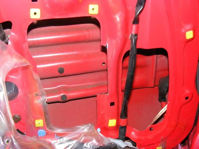
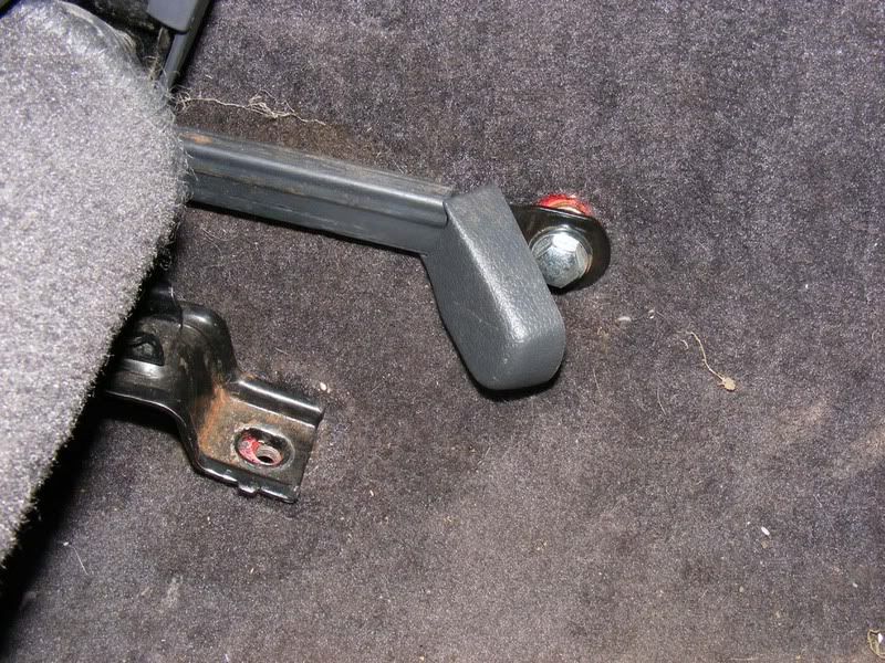
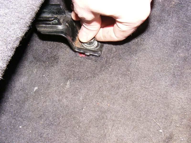
42. You need to find a suitable grounding point on the chassis, there are several potential spots in the Supra's boot, in my car I found someone had clearly been doing this before. The first two pictures show some rusty holes which look like they had been used for earthing an amplifier at some previous point. These were cleaned up with some sand paper to reveal bare metal which is very important to get a good ground connection (the car's chassis is directly linked to the battery's negative terminal). Obviously you will need to lift the carpet back to get to the metal underneath
Ideally you should ground each amplifier at a separate point but sometimes it may be necessary to share the ground return path. Make sure you terminate these connections well and ensure there is a solid connection to the chassis for current to flow.
43. The Supra's boot is a little bit tight on space so when installing a sub you may have difficulty with height of the box. For a newcomer to ICE I highly recommend you buy an off-the-shelf box for the sub you choose rather than fabricating your own. This is for acoustic reasons and you'll find a huge difference in speaker performance depending on the enclosure you use.
Note : There are typically two types of box used for a sub woofer, these are sealed and ported. They are exactly as you'd imagine, sealed is an airtight enclosure whereas ported has a tuned 'port' or hole for air to escape. The sub you buy will have details on whether it suits a ported or sealed enclosure but a sealed enclosure is quite normal. If you do start designing your own custom boxes then make sure you calculate the volume of air required for the box correctly - this is very important!
Assuming you have an off the shelf box and are short on space, the spare wheel well is an ideal place to gain some room (especially if, like me, you have no spare!). Obviously if you sacrifice the spare wheel you need to take other measures for puncture recovery i.e. a can of the 'fix a flat' style aerosol to limp you home.
Remove the wheel and use an angle grinder to detach the mounting bracket.
Now you can either drop your box in or, if you're feeling adventurous, fabricate an enclosure to allow your sub to sit in the spare wheel well.
44. The final wire to connect for the power supply is the remote wire and then you can power the amp for the first time
45. The remote wire is basically a low current wire which supplies +12 volts when you want to turn the amp on. This is a bit like a traditional relay where you have your beefy supply and return wires and then a small switcher wire which turns the device on. Typically your head unit will have a blue wire marked as 'rem' or 'remote' which outputs a +12 level when the head unit is turned on. Alternatively you can use a standard switch to the battery to allow you to manually turn the amplifier(s) on/off. For my install I decided to use the electric antenna's +12 volt feed to power the amps. Start by removing the cover in the boot
46. Now ease the wiring out and you'll find a connector for the antenna. Mine had already been meddled with as shown but take the bottom left hand corner's wire and splice into it with your 12 volt feed to the amps (use a voltmeter to check you have 12 volts when you switch the stereo on and 0 volts when you switch it off before you cut the wire!). To introduce your new wire either use spade clips or a block connector
47. Run this wire (use blue if you can, it's the standard colour for this) to your first amplifier. If you have multiple amps then you can piggyback the wires between each amp. First, cut the wire at an appropriate juncture so it reaches the first amplifier (allow a little slack too).
48. Now strip the ends - get some strippers like the ones shown from maplin etc and it will make life much easier
49. Twist the wires together to join them
50. Now fit it to the remote temrinal of the amp and you have the other end of the wire to run to the next amplifier in the system. this way, a single +12 volts from the antenna can supply all the amps. If you are running more than 2 or 3 amps then you should consider running a separate feed to a relay or directly form the battery via a switch because each amplifier will draw a small amount of current through this wire.
51. Ensure your + and - wires are not going to tough each other and fit any rubber surrounds or shields to protect them. My new Sony amplifier came with a big boot to cover the power connections as shown
52. By now you have all the power supply wiring complete as well as the RCA leads to feed the sound in so you can think about fitting the fuse at the battery and distribution block. It is worth powering up the amplifier at this stage to make sure your supply, return and remote wires are correct (typically there's an LED on the amp to tell you if it is on or in a failsafe state). Once you've proved the power supply is correct move on to some sounds.
53. OK all inputs are checked and OK so we'll finally do the remaining output wires to the speakers in the front. I usually do this in the boot for ease of access then relocate them once everything is working roughly. As mentioned earlier, over spec the cable and you don't have to use the bell wire that comes with the speakers (although normally it IS adequate). Strip about 1/4" off the wire
54. Slide the sheath over the wire which will protect the connector from shorting on adjacent wires
55. Trim the wire as necessary to suit the connector
56. Slide the connector over the bare wires (which should be twisted together)
57. Now crimp the connector on. You can use mole grips and hurt your hands whilst creating a poor connection or buy this tool (again Maplin or similar for about £10) and make a much better install.
58. Tidy the connector and trim any wires that escaped the connector
59. Now slide the sheath up over the bare metal of the connector for protection (and it looks neat)
60. Finally, fit the connector to the amp noting the polarity - ensure the + on the amp matches that of the speaker. Notice on the second picture that it goes + - - + so don't get confused here, this is quite common
61. On a 4 channel amp you will need two RCA inputs (first picture), usually a front and rear (or sub). In my case I was using three amps and required four sets of RCA leads (one for sub, one for the amp powering the two front speakers and two sets for the two sets of 6x9s in the rear). To handle this you can get splitters which make one RCA feed into two (see second picture). Plug your feed from the stereo into these splitters and you suddenly have your two RCA feeds to the amp (picture 3/4)
62. Now you can do a full system test, I suggest you power up each amp one at a time and each speaker one at a time as well for fault finding, in my case I did:
1. Powered all 3 amps with no speakers
2. Powered amp for the sub alone and tested the sub
3. Just powered the amp for the front speakers and fitted each speaker individually before fitting both together
4. Powered the amp for the 6x9s only and tested each of the 4 speakers one at a time before fitting all 4
5. Full test with all three amps and all 7 speakers
Now it's wired you have the fun bit, making parcel shelves, enclosures, custom door pillars, burying wires etc! At this stage you are about half way through an install but you've done all the wiring parts and the rest is about tidying up. Test the system operates correctly and then the tweaking can start.
Here's the way I set up my amps (once the speakers are all in place of course!):
1. Turn the stereo down to the minimum volume you will listen to and remove any additional bass or sound effects from the head unit. You want raw sound output with no equaliser interference at this stage. Start the engine and put your ear to each speaker - if you have electrical noise and your wires are properly routed then check for ground loops etc. You can get supressors which reduce the noise but they can only reduce it rather than eliminate it so you're better off finding the route cause
2. Put the head unit to about 80-90% volume and then power each amp individually, setting the gain to an appropriate value i.e. the highest you can without distortion of the sound. Note that you may need to go for a drive to test this because sticking your face next to the speaker will give you a very distorted idea of what the max volume is
3. Once all amps are individually configured, turn them all on and tweak to balance out the sound
You will have to start finding rattling bits of trim at this stage, especially with a sub - everything will be rattling, number plates, rear light covers, plastic trim etc. You can use sound deadening sponge or just remove most bits and pieces but this is usually an ongoing saga!
63. Once you've got everything installed and set up you need to start tidying up the wiring. The power and RCA cables strewn across the seats should be totally hidden from view and you need the wires from the amplifiers to the front speakers to be routed down the car too. Generally speakin power supply wires and speaker wires should be kept apart to reduce interference - that whining noise you get when the engine is running is due to interference and you need to try and avoid this. I run the power leads down the nearside of the car because the grommet and battery are on this side and then have the speaker wires (both RCA leads from the head unit and the small speaker wires from the amplifier) down the offside.
You are going to start routing a few wires between panels and behind the dash now so a word of warning - every time you place a wire double check it's not going to get crushed, burned, caught up in a motor/lever and otherwise damaged. Things like switches to turn fans on and move vents around can cause wires to get tangled if you aren't careful so use some common sense when routing cabling - as a general rule try and follow the stock loom for a safe path through the vehicle.
OK we'll start by fitting the door speakers. Follow the guide to removing a door card then test fit your speaker in the standard housing (you'll obviously need to remove the screws holding the stock speaker in and disconnect the wires to it!
64. If you've gone for a large speaker such as the 6" kappa perfect's you will find it fouls on the plastic cowl as shown
65. Remove the four gold bolts holding the surround in place (10mm or a philips screwdriver)
66. Once removed you'll see the plsatic covering for the inside of the door is all that's left, try to leave this in tact whilst working inside the door
67. Pull back the plastic to gain access to the inside of the door
68. Check your speaker doesn't hit this piece of metalwork, mine was clear on the driver's side (not on the passenger side though as shown later)
69. Now it's time to remove the piece of plastic causing us trouble so get a Dremel style tool out and cut away the problem area
70. This doesn't have to be particularly neat but try not to destroy the enclosure completely! I cut close to the edge as shown on the first picture and then ran up the side through the sponge. I than ran a cut along the inside of the enclosure as shown in the second picture. And finally broke away the two pieces and neatened up with a file as shown in the third picture
71. Once modified, attach the speaker to the plastic using the 4 mounting screws (they may not match up so you can make an adaptor plate if you need it or just use a couple of the screws which I did). Note that you will need access to the speaker terminals so make sure they face the cut out you made earlier as shown in the second picture
72. Test the door card will fit over the speaker before you go any further (it should do)
73. Now you need to route some wiring from the amplifier to the speaker which is a little tricky. You can modify and re-use the stock wires which makes life easier but if you want better wire or have rubbish stock wiring (my install met both criteria) then you might want to consider this. Pull the plastic door cover down even further and thread from the inside of the door through the side of the grommet to the gap between the door and chassis as shown. This is not easy but persist and you'll manage it, careful help with a screwdriver to move the grommet around may be required but don't split it!
Ideally you'd go through the grommet like the stock wiring loom but it's more difficult to do and takes time so I tend to go around the outside as shown in the second picture
74. Once you are through the grommet you need to go into the car itself. start by removing the 4 screws that hold the sill cover in place
75. Then clip it out, it should just pull away with a few clicks
76. Now get the single 10mm nut which holds the piece of plastic trim around the fusebox in place, just next to the accelerator pedal
77. Now ease the piece of trim away from the top and slide it out towards the back of the car, there should be a little resistance and some wriggling will be required but it should pull out easily
78. Now you can complete the feeding of the wire through the door in the other side of the grommet and pull it into the car
79. Ensure the speaker wires go through the plastic sheet before you connect them
80. Connect the two wires to the speaker, as always note the polarity of the wires. You want to have the positive terminal of the speaker connectored to the positive of the amp for all speakers (if you mix and match then you can have speakers moving out of phase with each other which is not good), I use the wire with the stripe as negative for all mine
81. Now refit the plastic surround, top first - it has some padding to hook into the door as shown for sound deadening
82. Refit the plastic trim of the driver's kick panel, careful to route the wire appropriately before you bolt it down
83. Now connect the wire to your crossover box or rub it to your amplifier. For me it was to a crossover as shown, again the only thing to remember is the polarity of the wires
84. On the passenger side there is a slight complication in the fact that the metalwork on the door is slightly different. If you try and fit 6" speakers they foul the door as shown
85. Remove the plastic door cover to get good access to the metalwork
86. Mark out the area to cut off
87. Then use a metal cutting disc to remove the offending material. It's very thin and easy to get through, at a push you could use a hacksaw but it would take much longer and even a novice could learn to use an angle grinder on this piece. Don't go too far into the metal because you reduce strength, just enough to fit the speaker in place. Use ear defenders and goggles and make sure you don't have anything that doesn't like sparks around e.g. fuel. Also, remove the speaker from the scene because it will catch all the metal filings due to the big magnet on it
88. You should end up with something like this
89. The only other point to mention for the passenger side is that when removing the kick panel you have one additional screw to undo which is the one for the plastic cover underneath the glovebox. It's the far left screw only and hooks into the plastic trim as shown
90. Follow the steps in the door card guide to refit and once you've finished you should have a stock look with a much improved sound to the system
91. Your next stage is burying all the wires and hiding crossover boxes. Start on the passenger side (slightly easier than drivers side), slide the seat forwards and slacken the 2 14mm bolts shown (remove the plastic covers by pulling them by hand if you have them fitted)
92. Slide the seat back and remove the 2 bolts at the front, again these are 14mm
93. Now pull back the cap as shown and remove the final 14mm bolt
94. You can now pull the seat from the car, there should be no resistance at all so if there is stop and check you haven't caught a wire
95. You're left with a view of the carpet and possibly the stock amp wiring, if you're ditching this (which I recommend) then just trace the wires back to the head unit and remove as shown in the pictures
96. The sill cover needs to be removed now, 4 philips screws and then clip it off
97. The green plastic retainer can now be unclipped along the sill by pulling it towards the door and lifting up
98. When you've finished you should be able to pull the carpet back freely as shown
99. Now remove the two 14mm bolts holding the seat belt bracket in place
100. The back seats need to come out for access underneath, there are two clips to pull - pull them up towards the ceiling and then slide them forward, they may be quite tight.
101. Slide the seat belts down through the holes as shown
102. Remove the seats and place them outside the car
103. You now have good access to the edge of the carpet and underside of the seats as shown
104. Remove the plastic retainers as shown by pulling them straight up, try not to pull at an angle or they bite harder. It will need a bit of a tug - there should be one either side
105. Head for the corner where the passenger's feet lie and wriggle the carpet down so it is clear of the trim
106. Now you should be able to lift the carpet completely and have access down the length of the car for routing cables
107. The only area you need to free up now is in the front passenger footwell, remove the 10mm nut shown
108. For this side you need to remove the left hand screw as shown
109. Now remove the trim by sliding it out
110. Pull the carpet up at the front and slide your main power cable underneath, note we are only routing power cables down this side not the RCA or speaker signal wires
111. Route the cable along the underside of where the seat will be mounted (down the middle of the seat well clear of the mounting points to avoid any problems trapping the wire) and feed the wire up under the back seats as shown
112. Ensure the wire is underneath all sound deadening and padding material as shown
113. Clip the carpet back into place, again make sure your power lead isn't too near the point where the rear seats clip into place
114. Refit the carpet you removed from the corner and push it flat
115. Clip the green plastic clips back in to hold the carpet down
116. Fit the seat belt retainer bar back in place with the two 14mm bolts, ensure they are tight
117. Put the passenger seat back in the car
118. Line up the 4 mounting holes and fit the stabaliser bar with its 14mm bolts
119. Loosely fit all 4 bolts to make sure the seat is squarely lined up then tighten them down
120. Onto the driver's side now, we will route all our speaker cables down this side. I will show the differences for this side, most of it is identical to the passenger side, first you have to slide the seat about by hand obviously because it isn't spring loaded like the passenger side
121. You have an electronic seat for the driver's side so remove the connector as shown, this just pulls apart
122. The rest is the same as the passenger side (note when you refit the seat, there is a dowel on the front left bracket that must drop into place, if the carpet gets in the way you'll struggle to refit so just a head's up), you'll need access to under the steering column for cable routing. Also you need the head unit out so remove the screws holding the centre console in place
123. Remove the gear stick by untwisting it (I think this is all covered in the turbo timer guide in more detail if you get stuck)
124. Pull the gaitor up over the stick
125. Unclip the three top spring clips by pulling forward, there should be little force required
126. Unplug the multi plug to the cigarette lighter (squeeze and separate) then unclip the hazards, rear demister and fog light multiplugs by pressing the locking plastic tab then pulling clear
127. Remove the surround
128. Now remove the cage holding the stereo in place, 4 philips screws
129. Remove the head unit and as much wiring as you can
130. Now remove all the philips screws under the steering column
131. Don't forget the two under the bonnet release
132. Unclip the air duct for the heater by pulling down with moderate force
133. Now you have good access to all the wiring, be aware of the movement on all the pedals and avoid routing wires near them
134. Run your RCA leads under the carpet as you did with the power wire and feed them up to the back of the head unit. If you have a crossover box then pop this behind the cover for the steering column on the right hand side behind the ducting you removed. Once you've done this, refit all the bits you just removed and test the RCA cables/speaker connections are working
On the passenger side for a crossover box you can route the cables up the back of the glovebox (you'll need to remove the 3 lower screws and cover to feed the cables/crossover in place) as shown
Hopefully that covers everything you need to install an amp and speakers including burying all the wiring and making a totally stock look. Some time will be required in setting up the system but you should find it's significantly better than any standard system.