
Guys, this is a guide for disassembly only because I was doing a straight swap for another subframe - the one thing I would mention is if you try and use this for REBUILDING the subframe then be sure you have used matchmarks for camber adjustment bolts and torque up necessary with the weight of the car on as documented in the TSRM.
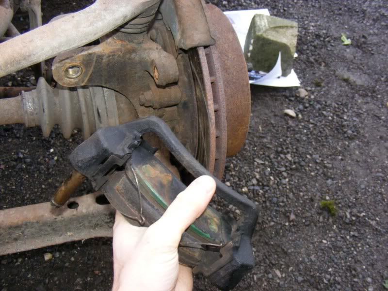
Step 1 - OK, continuing on from removing the subframe there is now a heck of a lot to strip down. There's more work in the strip down than in removing it! There are 2 14mm bolts holding the caliper carriers on, remove these then remove the carrier with pads and clips
Step 2 - Back to the usual 3/4" (or 19mm) socket and breaker bar so you can crack off the wishbone (upper arm) bolts and get them turning
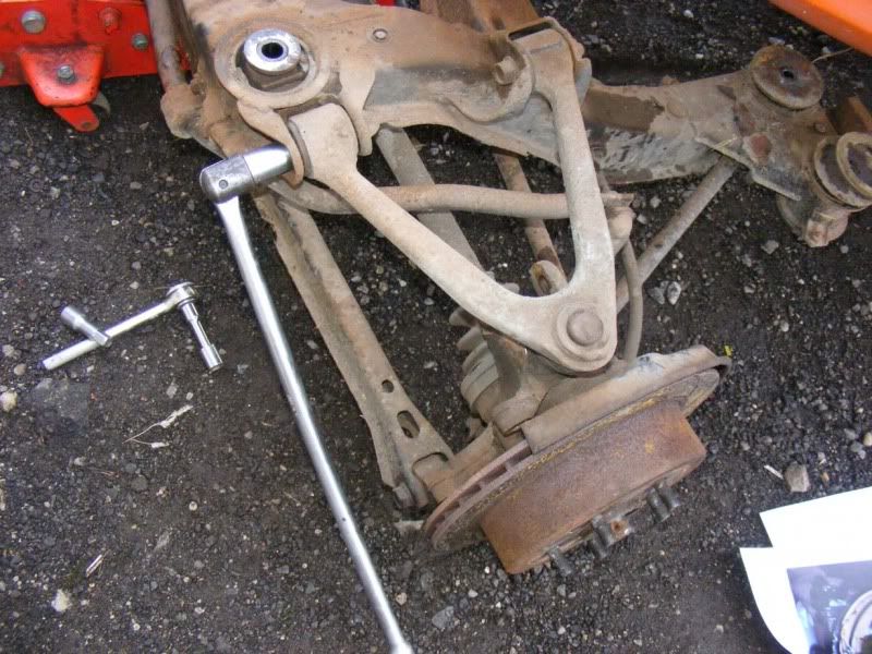
Step 3 - Once slackened, use a spanner (or another socket) to hold both sides of the nut/bolt and remove completely
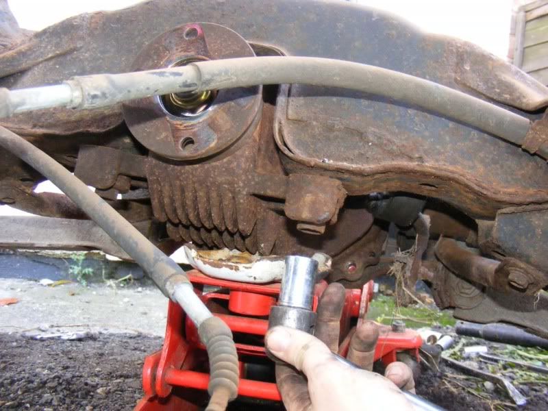
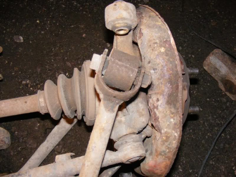
Step 4 - Remove the 17mm nut holding the wishbone to the hub via the balljoint. To test a ball joint, rotate it in all orientations, it should be a smooth feel ant not get stuck in any places. If the boot is split you will need to sort it
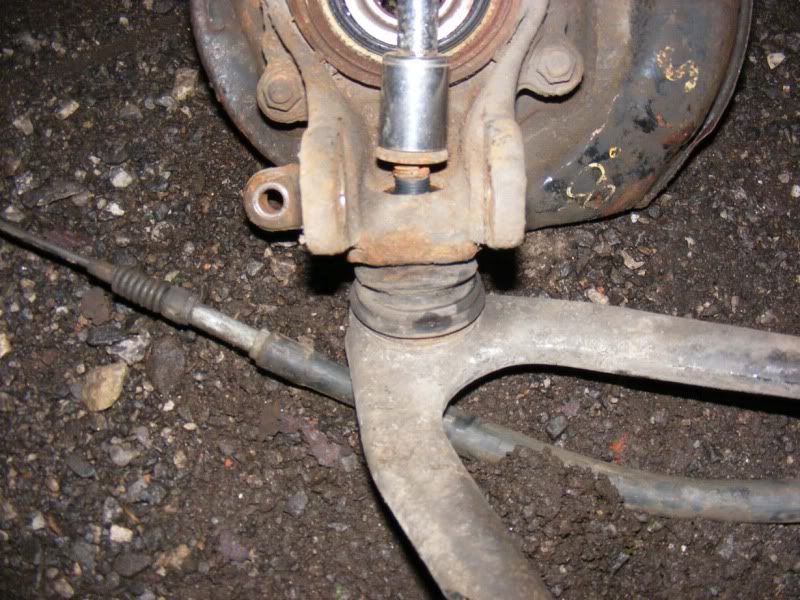
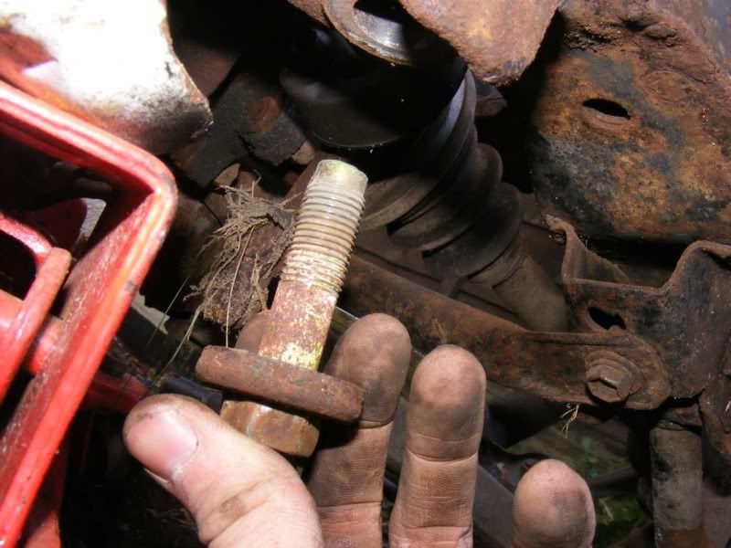
Step 5 - Once you have removed the nut, screw it back on the threads a couple of turns
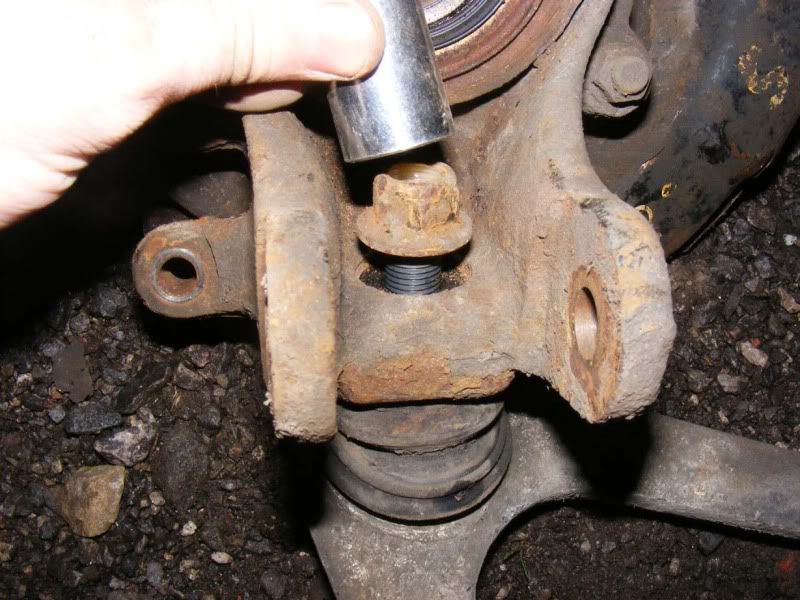
Step 6 - Replace the 17mm socket (preferably an old one) and give it a firm smack (be brave, tapping it will do nothing) with a lump hammer, this should pop your ball joint off easily. The shaft below the threads is tapered so it is tight against the hub.
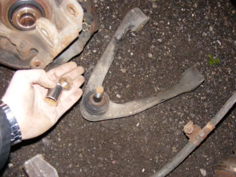
Alternatively get a ball joint splitter (two types, one with a bolt you tighten that I recommend because it won't tear the boot of the ball join and one which is like a 2 pronged fork which work but often damage the rubber boot).
Step 7 - Remove the nut once the ball joint is free and your wishbone should pull away (you may need to use a pry bar to encourage the bushes to pop out their mounting points but usually a wriggle will suffice)
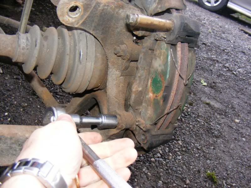
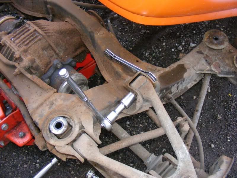
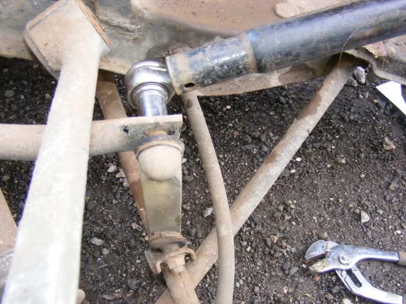
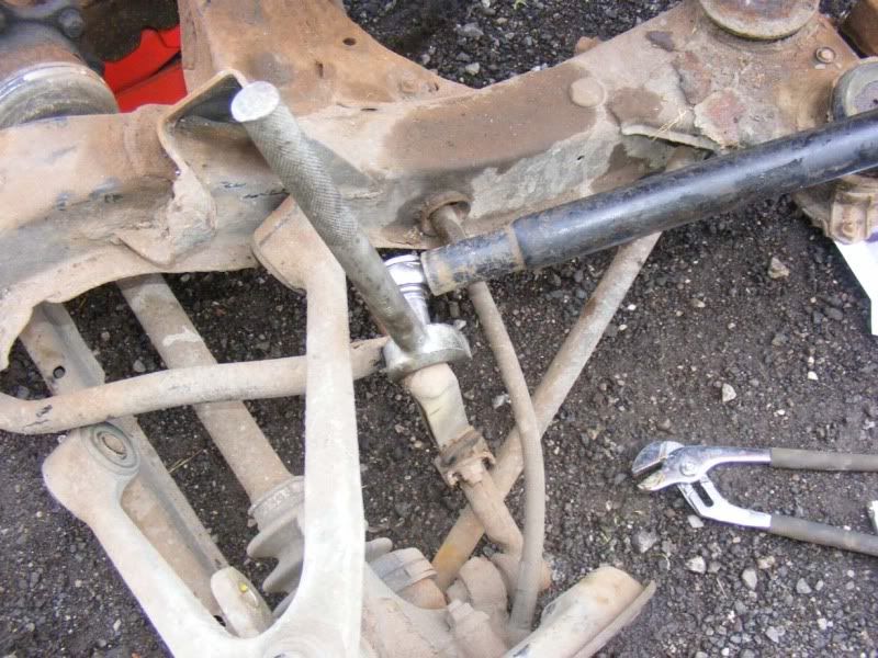
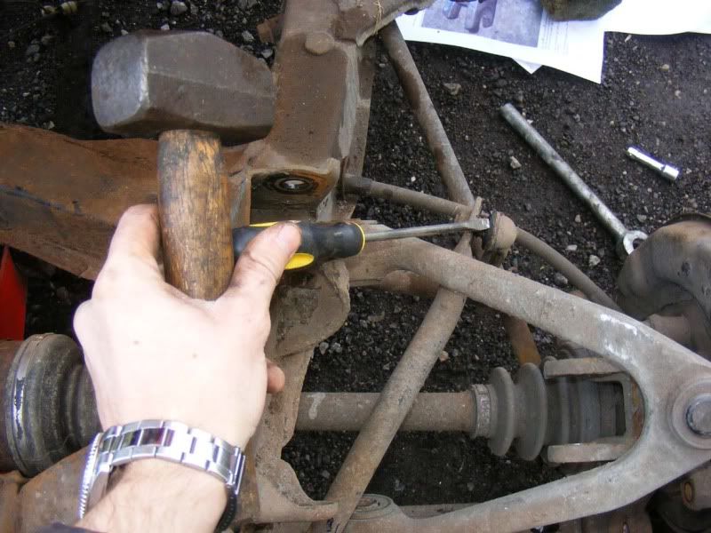
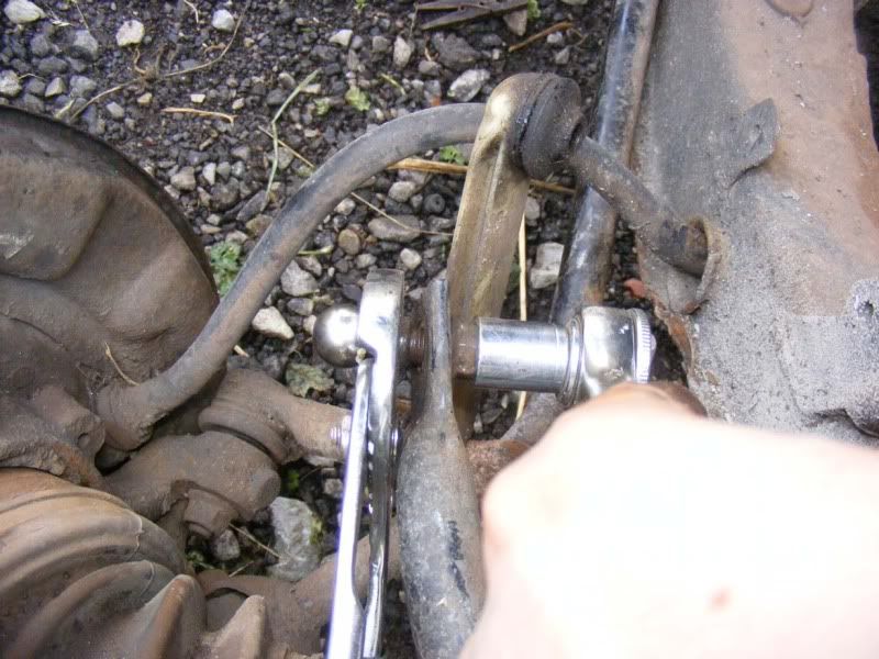
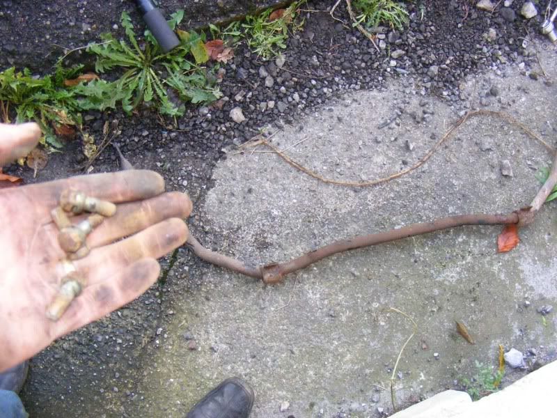
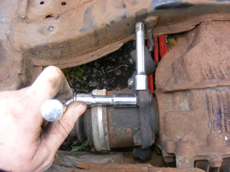
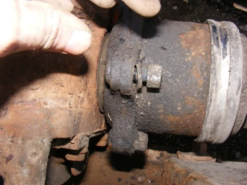
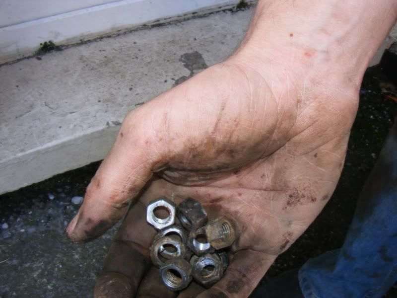
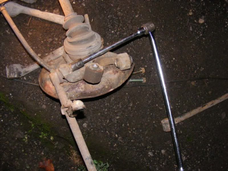
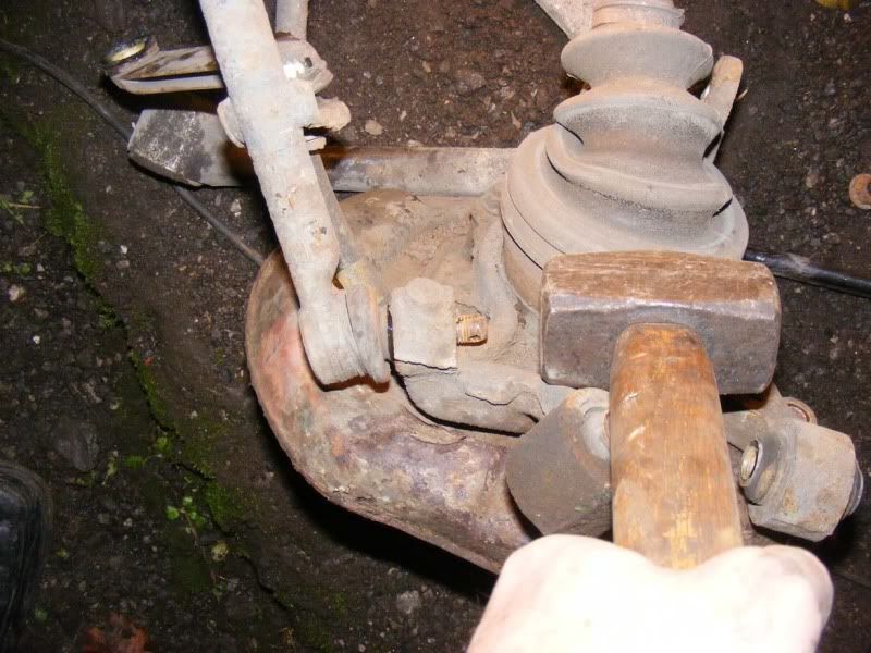
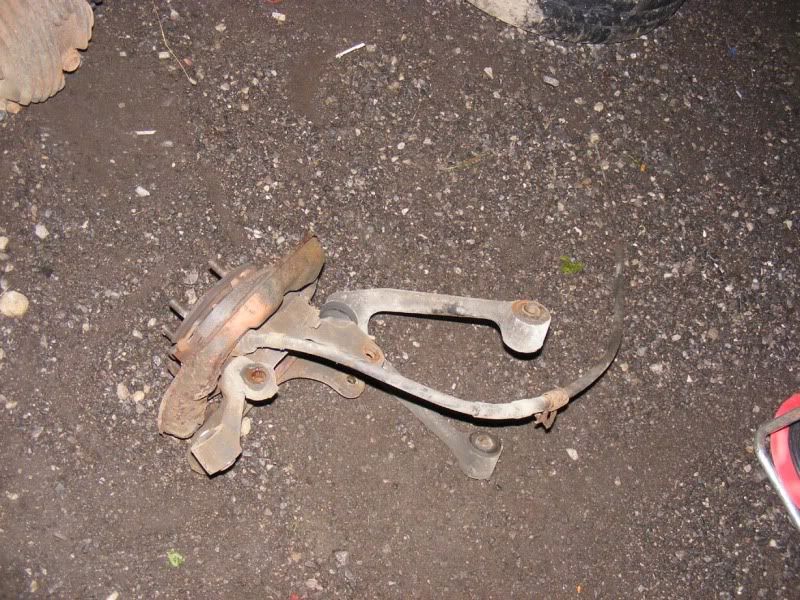
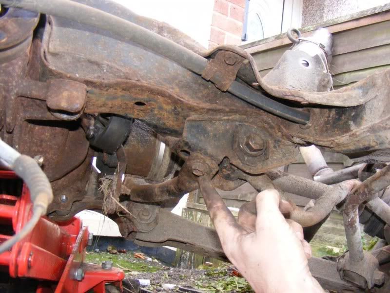
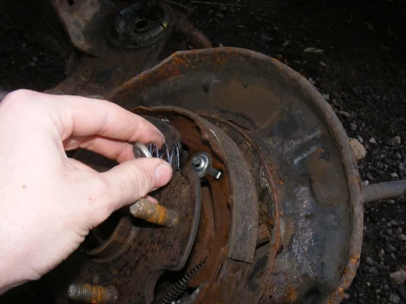
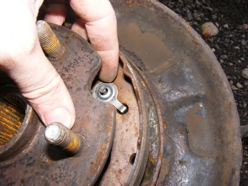
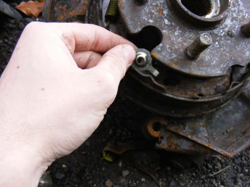
Step 8 - Now we have to remove the stabiliser bar (anti-roll bar) stabiliser link (drop link). This is a double-ball joint affair and can be a bit of a pain. There are two 14mm nuts to remove and if you're lucky they will undo without spinning the balljoint (picture 1). If they don't then you can put a 2 pronged balljoint remover down and apply a little leverage which should be enough to stop it from spinning (pictures 2 and 3)
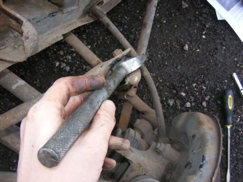
If they are really stubborn, just knock the link of its ball joint with a pry bar/chisel/flatblade screwdriver to expose the ball (picture 4) and then grab the ball joint with mole grips and remove that way (picture 5)
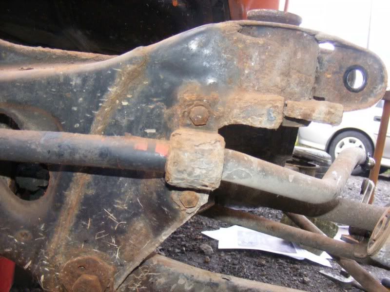
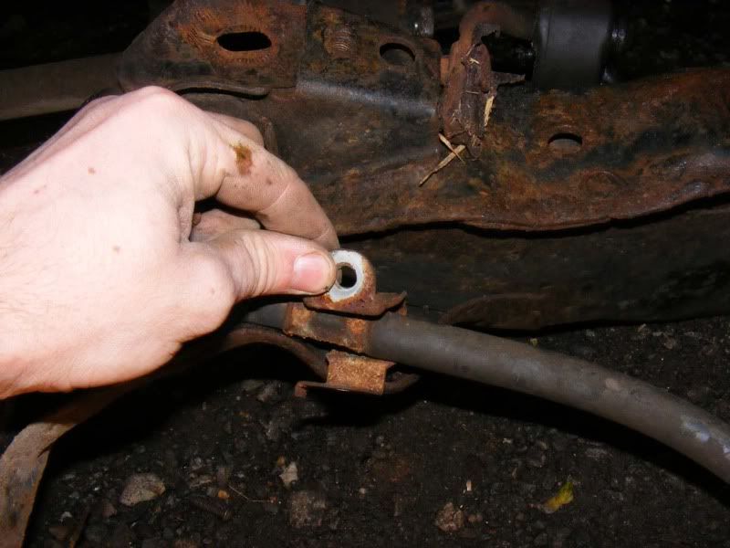
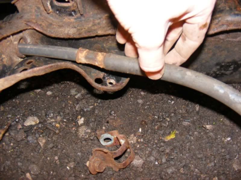
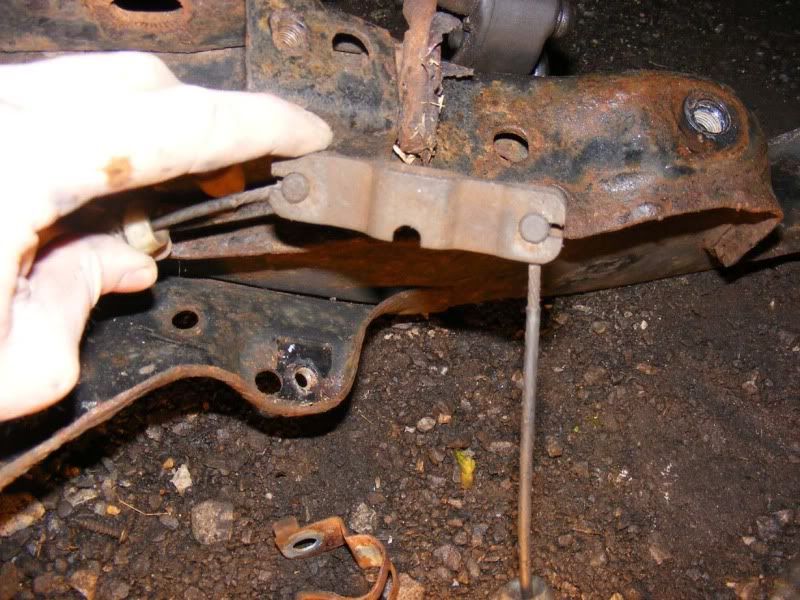
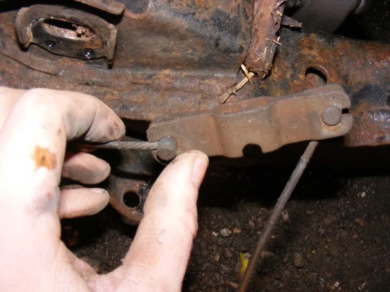
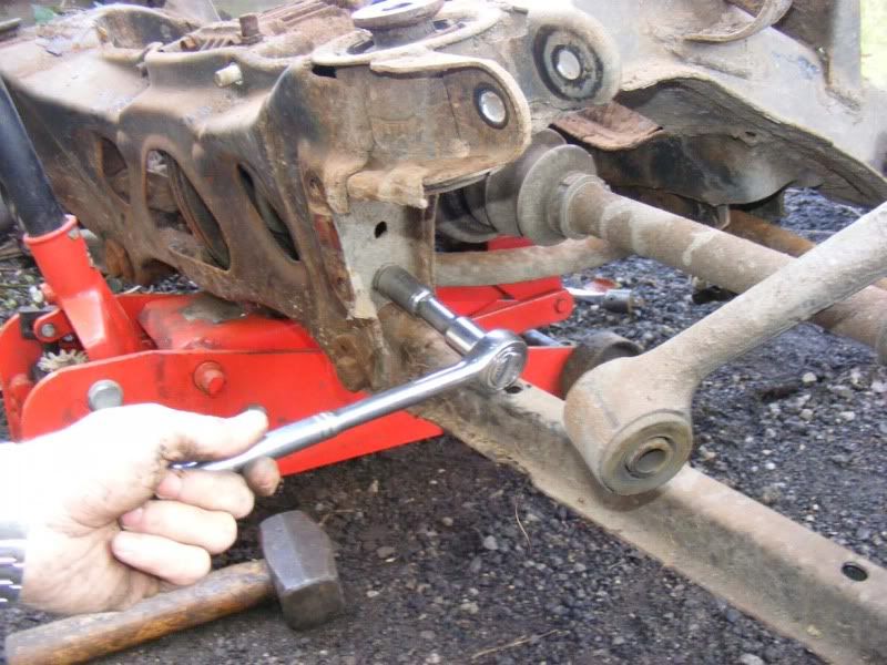
Step 9 - You can move on to the rest of the anti roll bar now - there are two brackets (pictures 1 and 2) that hold it to the subframe, each has two 12mm bolts. Remove all 4 bolts and the rollbar drops away (picture 3)
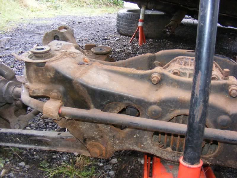
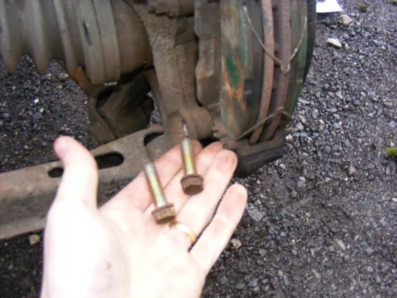
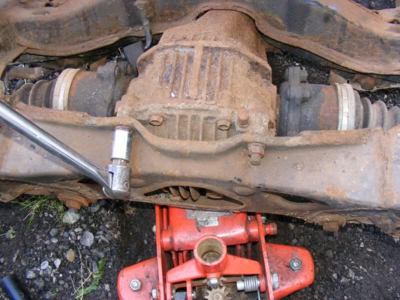
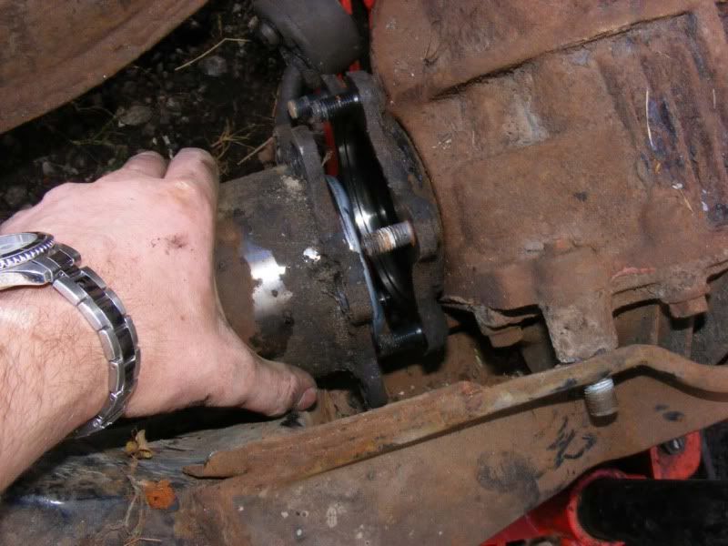
Step 10 - Next the diff, it's a big piece of what you have removed and has some hefty fasteners attached, we're back in the 3/4" realm again. Start with the two nuts at the back of the subframe as shown in the picture
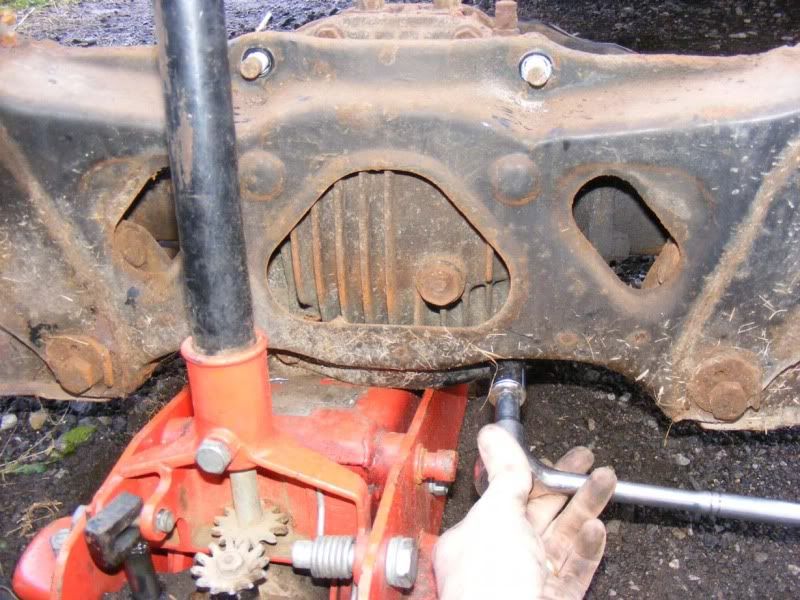
Step 11 - Next get the two underneath, you can't see them in the first picture so I took another to show you the big bolts you are removing
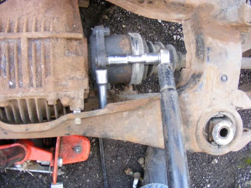
Step 12 - Now jack things up again a little to give you some room to work and move to the front of the diff where the prop attaches. You have two bolts (each with a washer too) to remove here
Step 13 - Now we have a little bit of ingenuity! I advise you crack off all the driveshaft nuts BEFORE you remove the prop and then you won't need to do this bit but seeing as I didn't I will show you how to deal with it!
The driveshafts will rotate freely now so you can easily wedge something (in my case an extension bar for a 1/4" drive ratchet) between the subframe and the flange where the driveshaft meets the diff. Simply rotate the driveshaft/diff flange until it makes contact with the bar and holds it against the subframe then you can apply force to the nut without it just spinning.
Step 14 - Do this a number of times until you've removed all the nuts and washers too (you may not see them under the dirt but they are there, don't lose them!)
Step 15 - Once you have removed all the nuts you can use the CV (constant velocity) joint's flexibility to pull the shaft away from the diff
Step 16 - This is how I wedged the other side
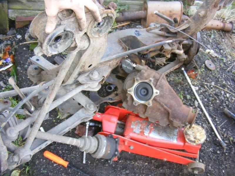
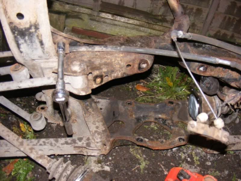
Step 17 - When you have finished, simply lift the subframe up (from the front) and it will peel away nicely leaving you a diff on the jack. The subframe still ways a bit on its own so be careful and use two people if possible
Step 18 - Now the diff's out the way we'll finish removing the two hubs and driveshafts from the subframe. We’ll start with the hub, remove the rubber inspection bung with a flatblade screwdriver and look after it (they always go missing!)
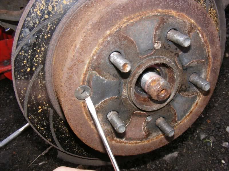
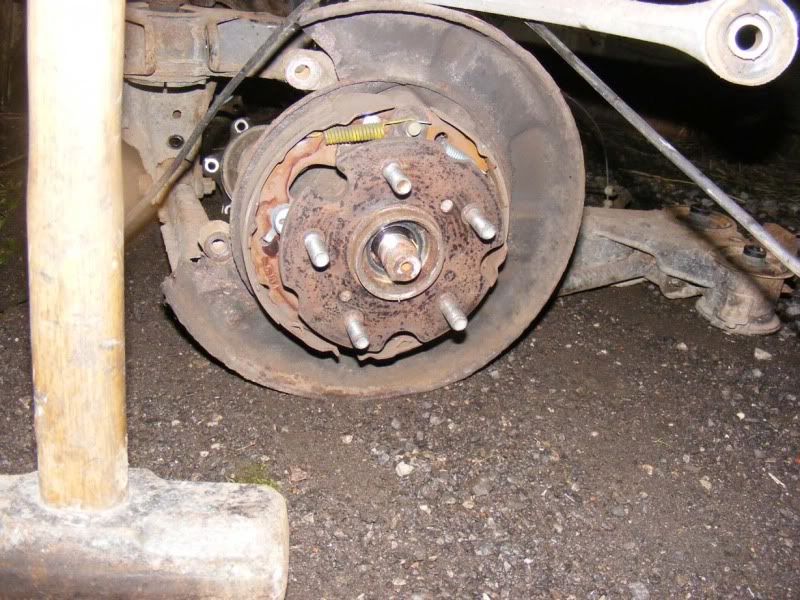
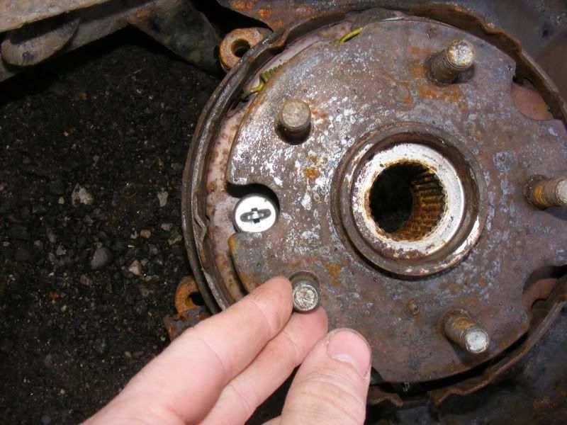
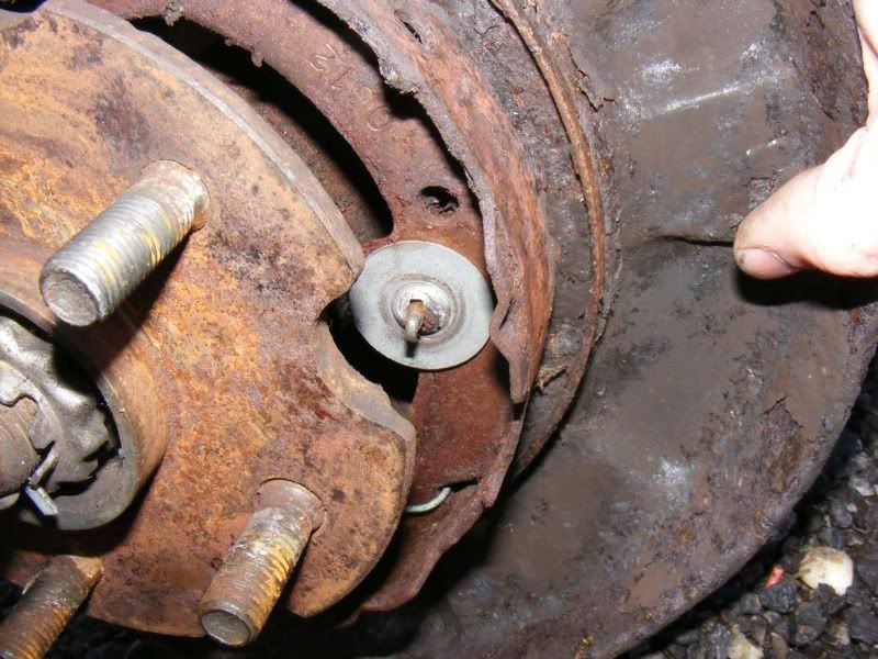
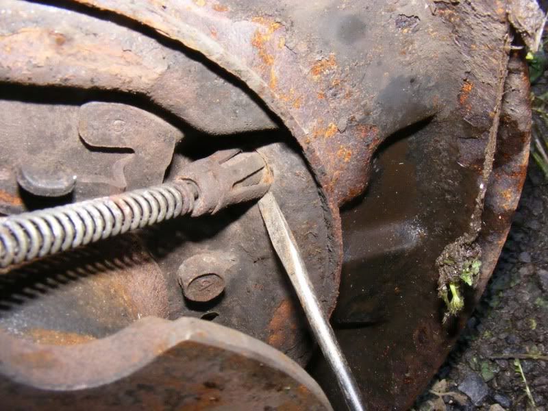
Step 19 - Rotate the hub (which may be very difficult to do) until you can see the cog for the handbrake adjuster which is at the bottom when everything's the right way up! Use a torch to help you with this
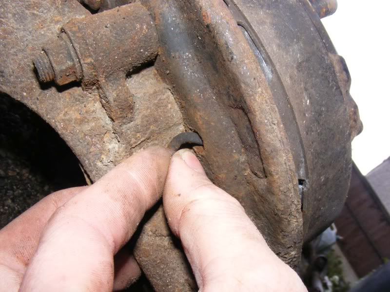
Step 20 - Insert a flatblade screwdriver and rotate the cog upwards i.e. put the screwdriver in so it points at the floor then push the handle down so the tip finishes pointing at the sky, this will slacken off the handbrake shoes. The picture shows the adjuster wheel you are moving inside the hub
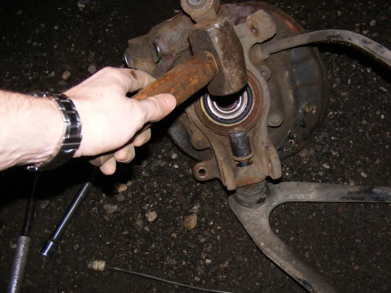
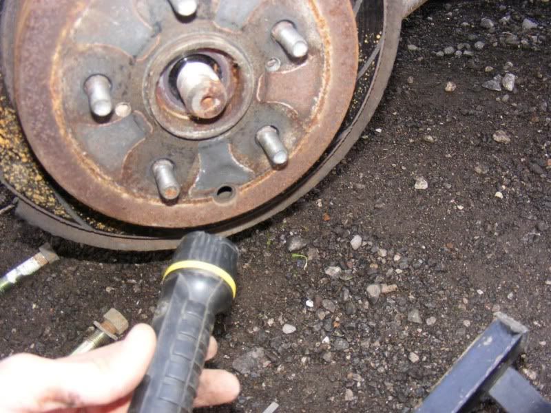
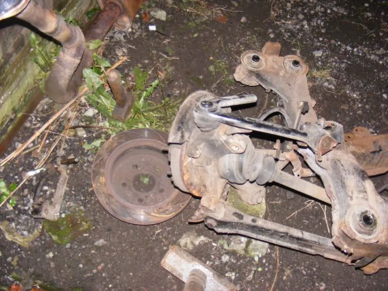
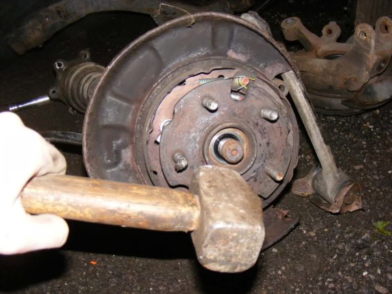
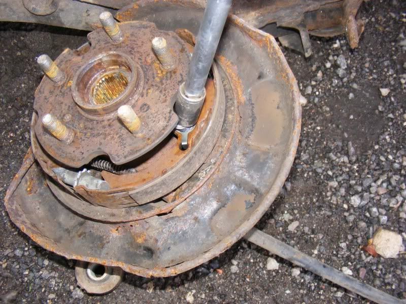
Step 21 - It can still be a real pain to get discs off and there's no substitute for a massive hammer. I have never warped or fractured a disc and I've hit some blooming hard I can tell you! There is a gap in the backing plate for the disc which is ample big enough to give a big hefty blow with a very big hammer (hammer shown in picture 2 along with the hub just after the disc is removed). Follow through with one single good blow and the disc should drop away as shown in picture 1
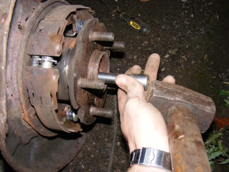
Step 22 - The driveshaft is still inserted in the hub so we better get rid of that now. Again a large hammer usually does the trick (although you can use pullers if preferred), give a sharp blow square on the end of the shaft and it will pop into the hub nicely (picture 1). Then use a suitable drift (extension bar again for me) to tap the shaft out (picture 2)
Step 23 - Now remove the 12mm nut holding the handbrake clamp onto the subframe (picture 1), this will then bend open (picture 2) allowing you to free the handbrake cable from the restraint and remove the metal clip altogether (picture 3)
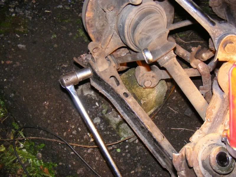
Step 24 - 3/4" socket and a breaker bar against a spanner can be used to detach the 'number 2' lower suspension arm from the hub
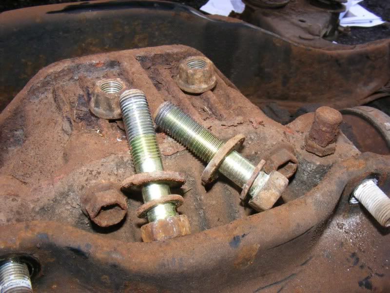
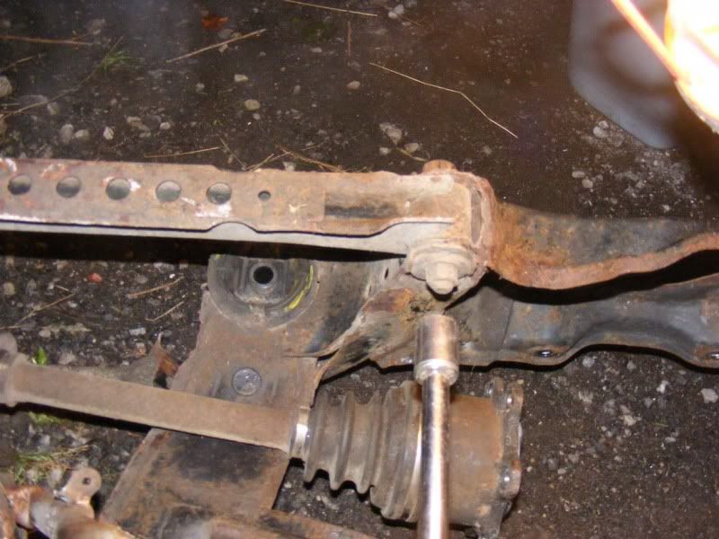
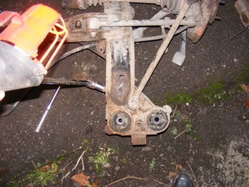
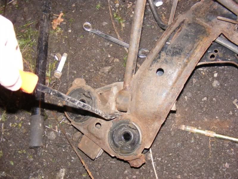
Step 25 - Go to the inside of the subframe to remove the second nut on the lower suspension arm, this is one with a cam on it to adjust your suspension geometry so mark it up if you intend to put this back together. Once you've got the nut off, smack the bolt with a hammer to push it out and hope it doesn't snap!
Again, tap out with a drift of some sort. Once you've pushed the cam proud of the subframe you can use a lever to encourage it out, I went for the trusty ball joint splitter again (picture 2). Heat can sometimes help with stubborn bolts, if you go down this route then hold a blow torch on for a good minute then have a stab at it.
Keep those camber bolts safe, they cost about £10-£15 each from Toyota
Step 26 - With both bolts removed, use a pry bar to ease the lower arm out as shown
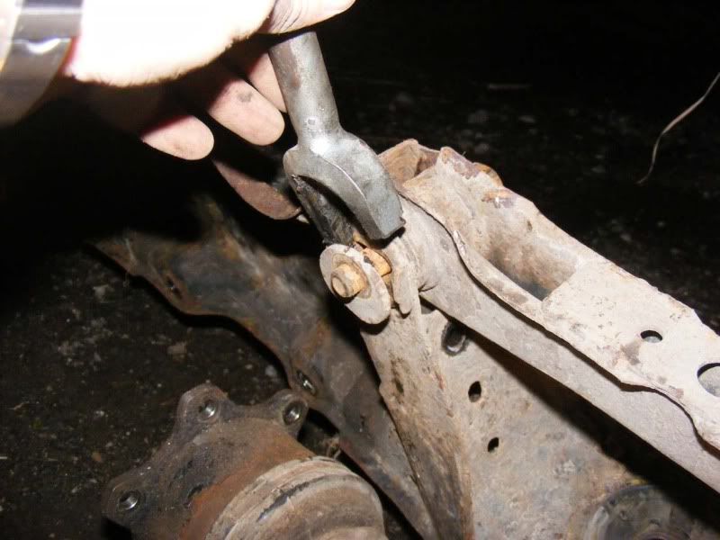
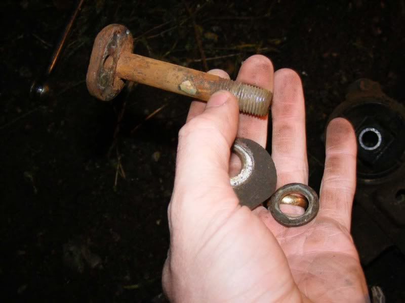
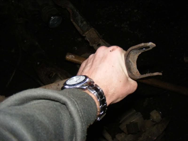
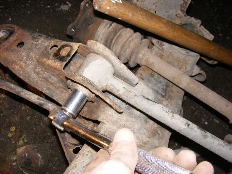
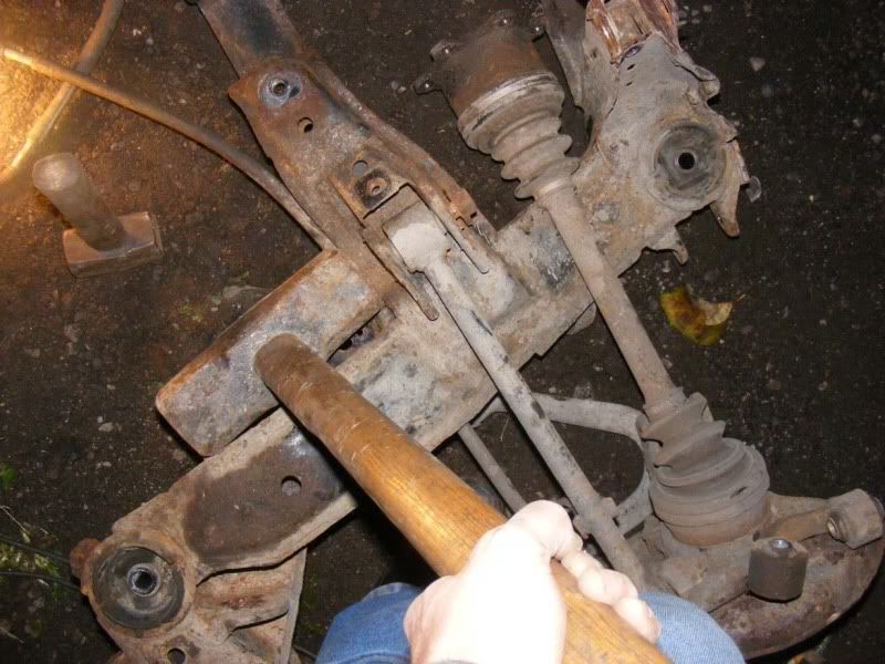
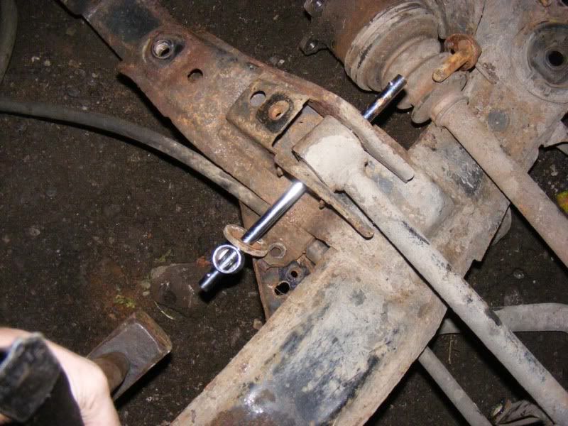
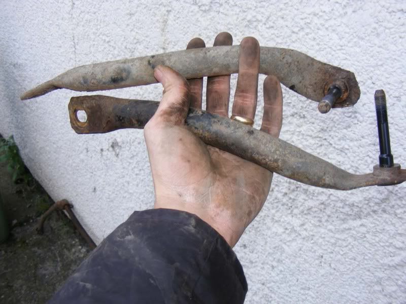
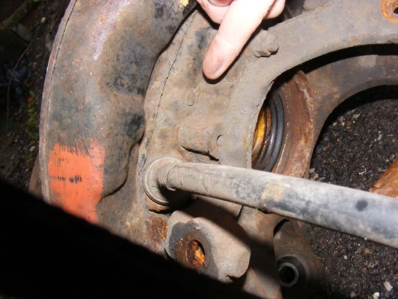
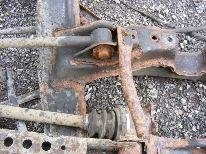
Step 27 - Next is the strut rod that is another connection between the subframe and hub. There is a long bolt going through the subframe which you need to remove (picture 1), and then a u joint on the hub which is a socket/spanner affair shown in picture 2 (all the normal 3/4"). Again, use a pry bar to ease the bar out the joints
Step 28 - With both bolts removed, pull the strut rod clear
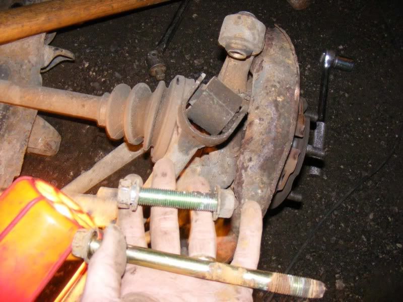
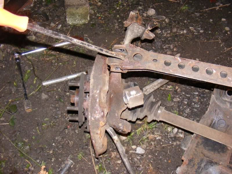
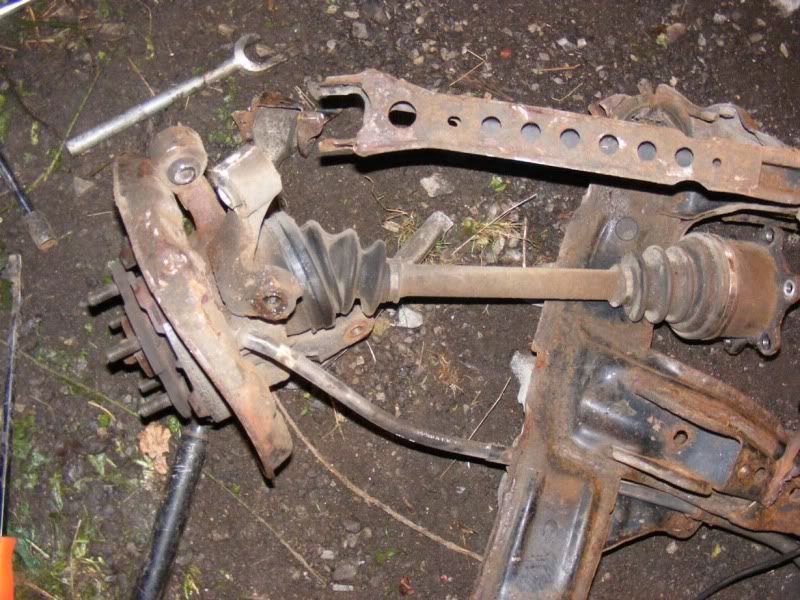
Step 29 - Next is the 'number one' lower suspension arm. On the subframe end remove the nut and cam (mark if appropriate) as shown in the first picture. Give the bolt a firm smack to remove (picture 2). Then use a drift to knock the bolt all the way out (you can see it has just popped out onto the driveshaft on the third picture)
Step 30 - The other end of the lower arm is connected to the hub via a balljoint, remove the nut and hammer out (refit the nut first unlike shown in the picture!!)
Step 31 - With all that disconnected you are just about ready to pull the hubs away, simply rotate the handbrake cables so the barrel and cable line up with the cut out in the equaliser bar and they slide out. This will allow you to pull the cables through the subframe and separate the hub
Step 32 - There's another two stabiliser bars on the subframe which are simply two 3/4" nuts then they drop away as shown
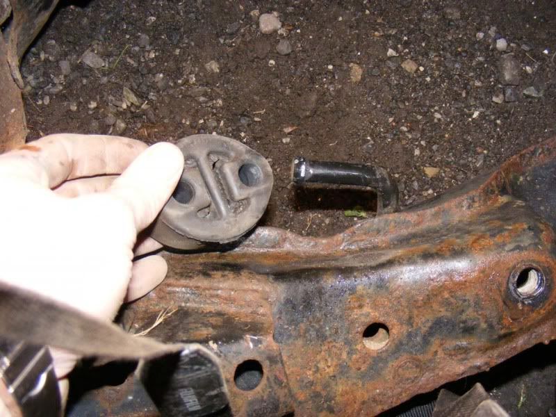
Step 33 - Don't forget to pop the exhaust hanger off either!
From here you can disassemble the diff, driveshafts and handbrake shoes. I'll pop some pictures up if I do any work on these in the next few weeks
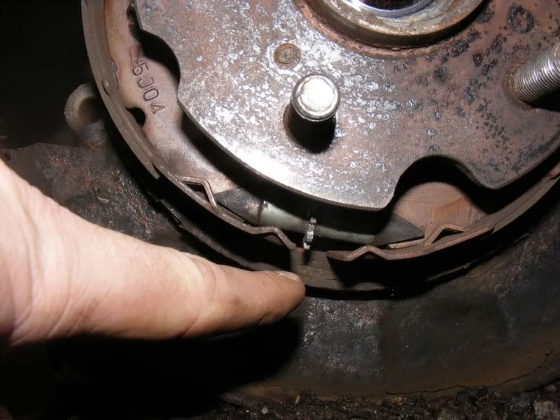
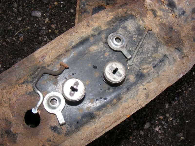
Following on from here we need to strip the handbrake assembly off the hub, this consists of two pads, an adjuster, a few springs and some collets and pins.
Step 34 - Rotate the hub until the cut-outs line up with one of the collets
Step 35 - You now need to push the collet down to compress the spring underneath it, this will allow you to twist the collet through 90 degrees so that the pin will release it through the cut outs. If you can do it by hand this is easiest, failing that you can try using a socket or a pair of pliers. Note you may need to hold the pin in from the back of the hub which is shown in the second picture
Step 36 - Once you have rotated the collet, it will pull away from the hub and you should take the spring with it. It's a bit tricky the first time you do it but after a while they're no problem
Step 37 - Now remove the pin guide, this simply lifts away. Note there are at least two types as shown in the pictures, the one shown in pictures 1&2 were off a JDM 92 and the third picture is from a 90 UK car
Step 38 - Free the pins from the hub, one side pushes straight out and the other is cranked (See second picture)
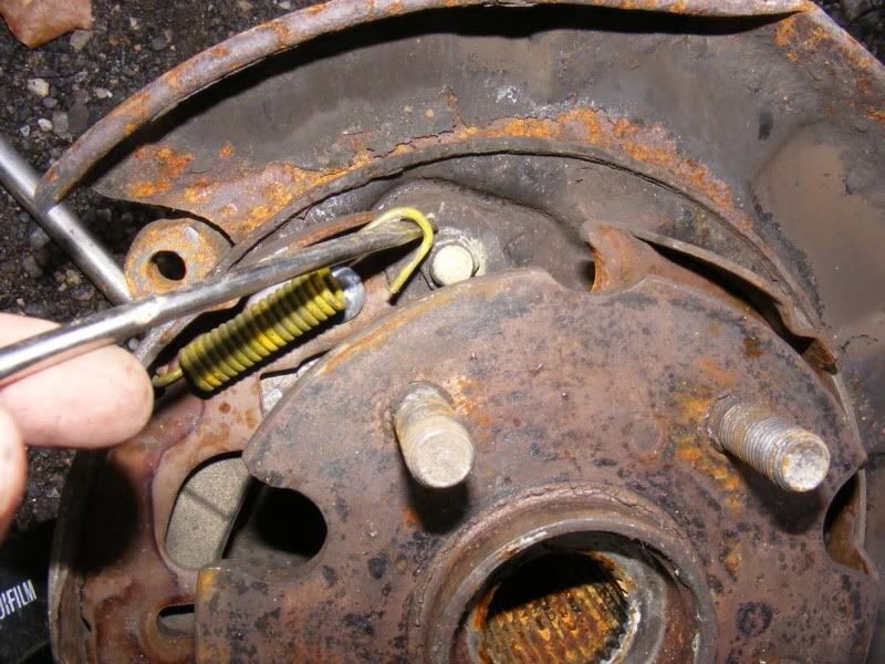
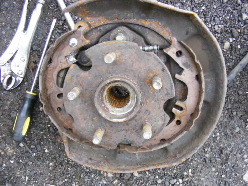
Step 39 - Onto the 2 main springs now, either use pliers or a screwdriver to unhook them from the hub - they will require quite a bit of pressure. Once they are off the centre pivot, simply unhook them from the handbrake shoes
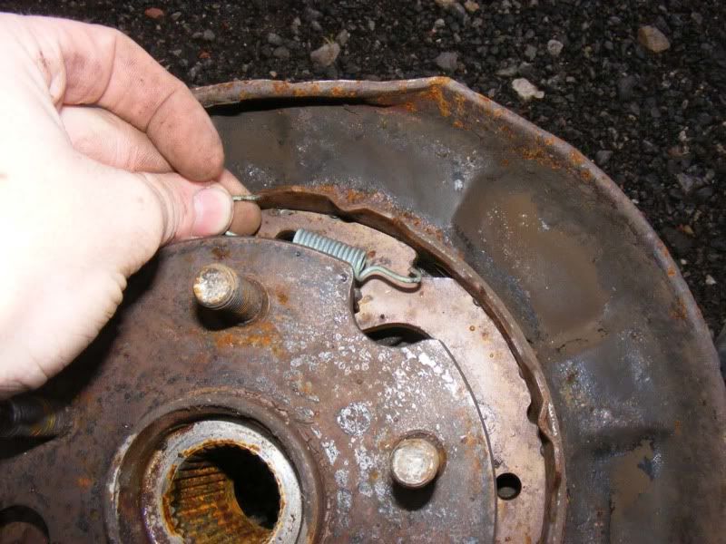
Step 40 - Now the shoes will open up and pull down off the hub as shown
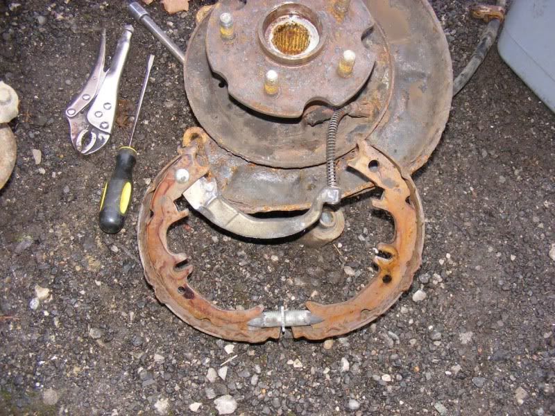
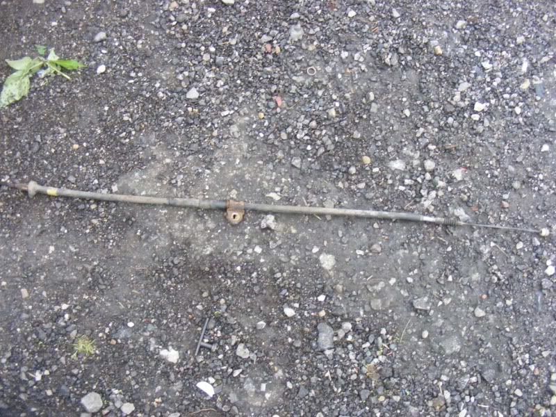
Step 41 - The handbrake cable needs to be removed by pushing the spring back and then forcing the cable down so that it can slide out of the mechanism as shown
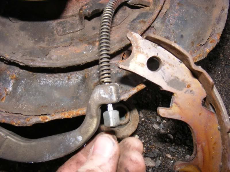
Step 42 - You will probably have left the bar and spring behind as shown, remove from the hub
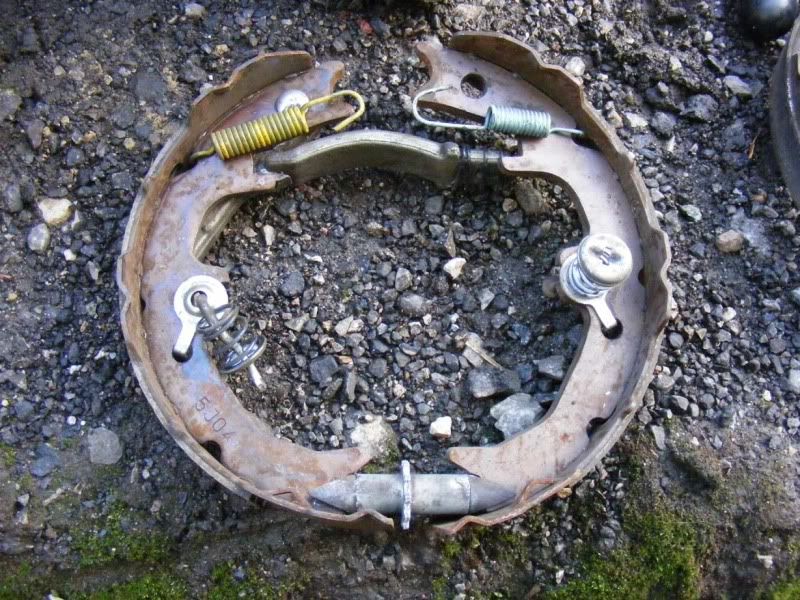
Step 43 - Here's the complete assembly for reference
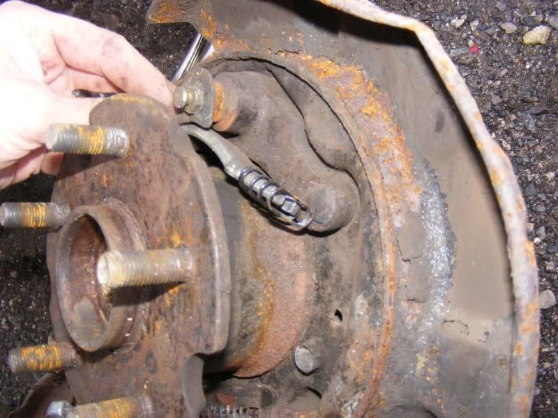
Step 44 - The final thing you may need to remove is the handbrake cable which has splayed legs that come through the hub, push them in with a flatblade screwdriver whilst pulling the cable from the back of the hub. It's a little bit fiddly but take your time and it's not too bad
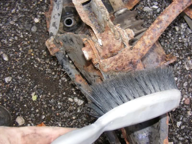
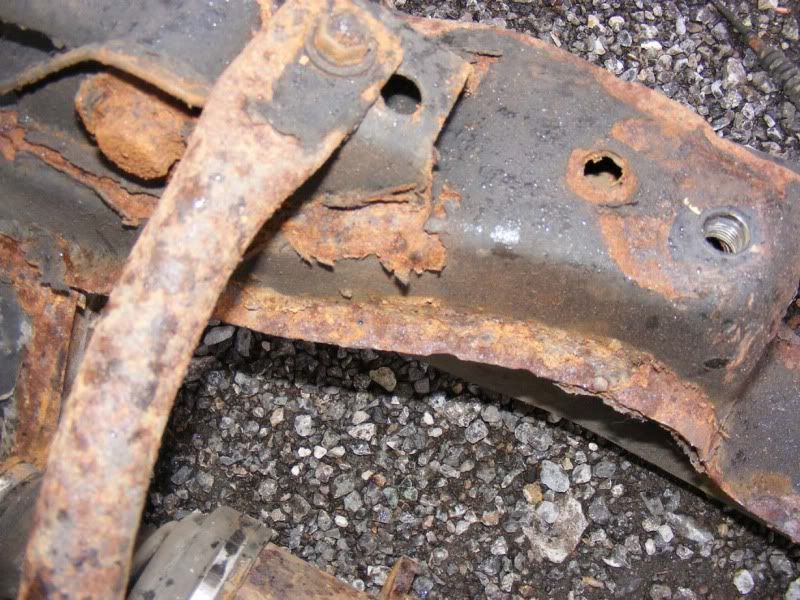
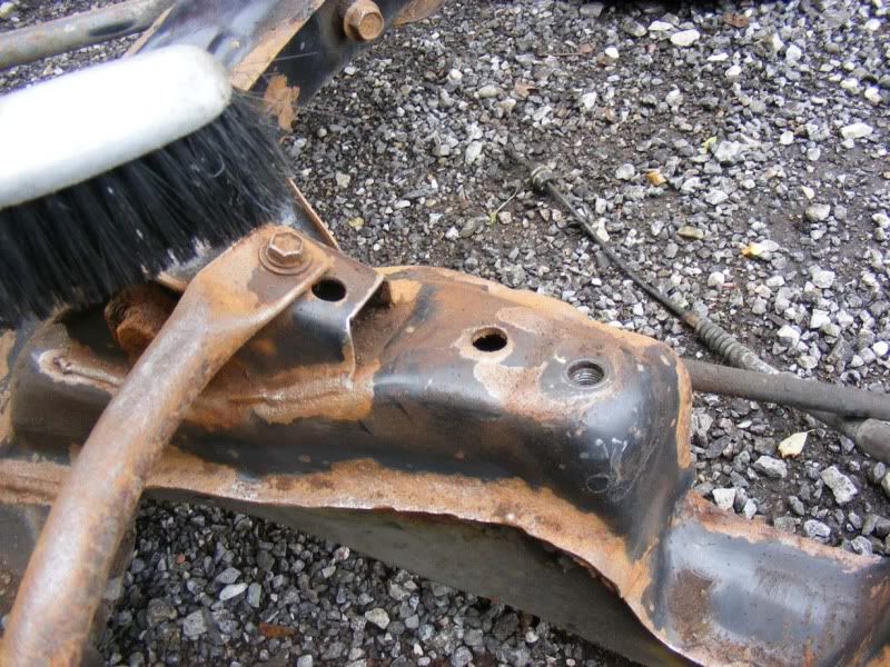
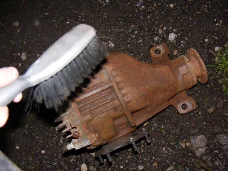
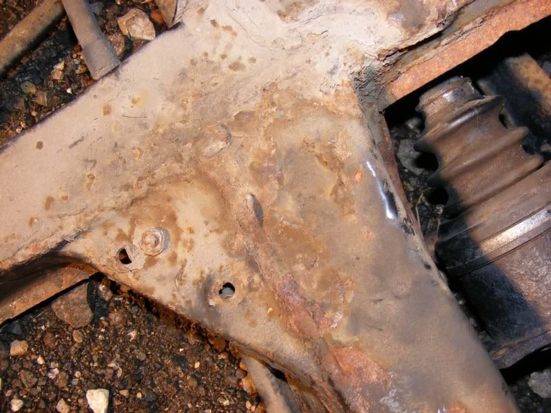
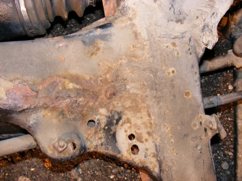
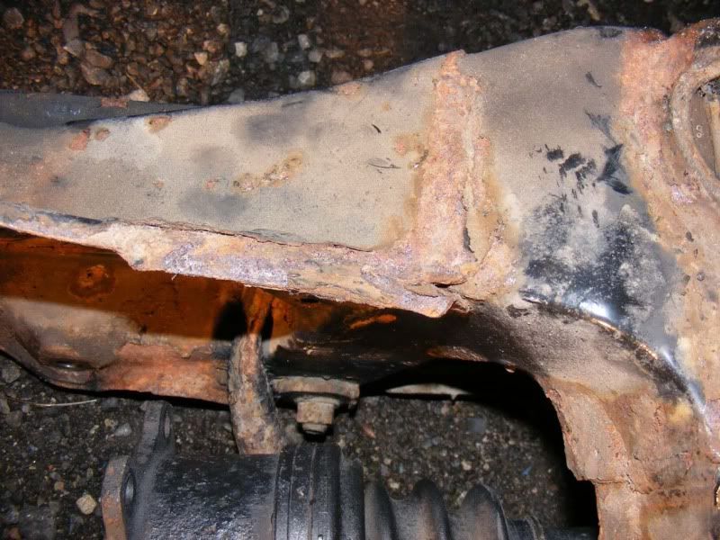
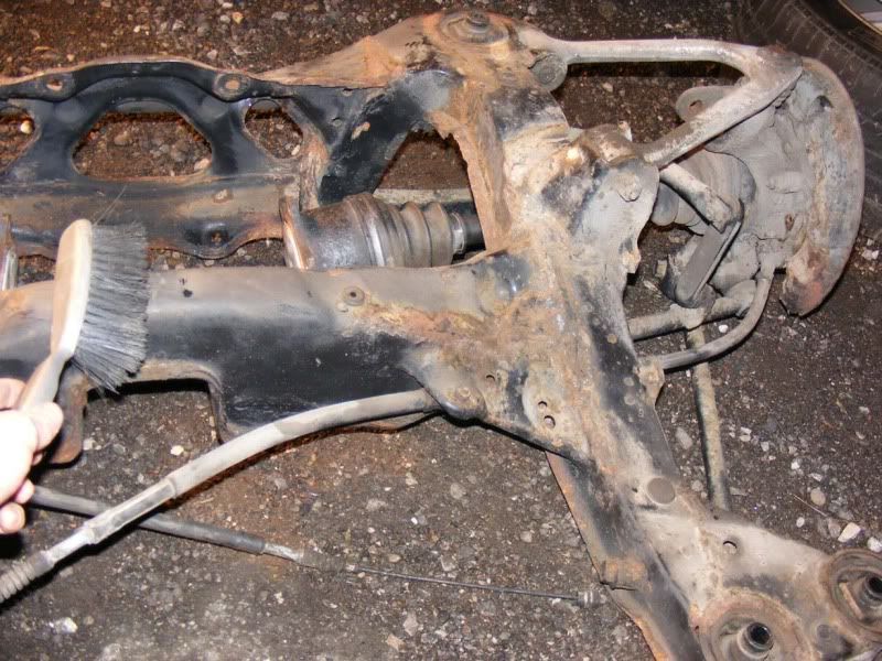
Step 45 - Now we're onto clearing up the frame itself, start by brushing off any loose debrit and dirt
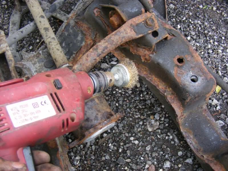
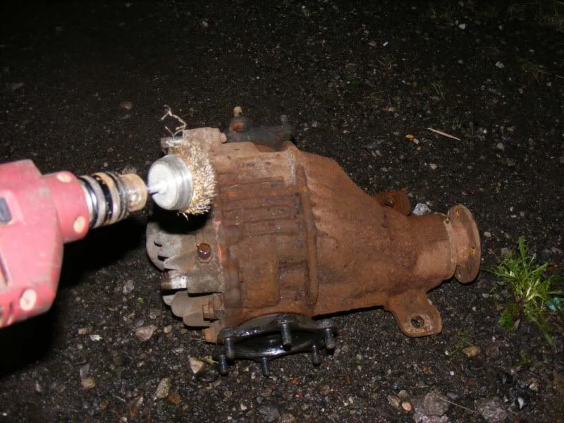
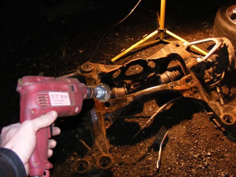
Step 46 - Now use a drill with a wire brush attachment to go over the whole subframe. You can do this as many times as you like to get a good finish
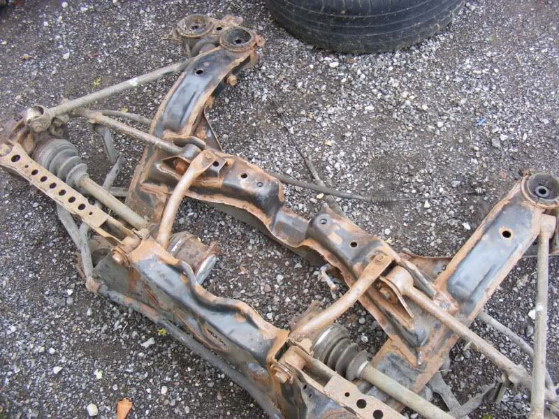
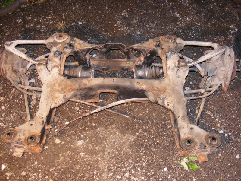
Step 47 - When you've finished you should have something like this
Step 48 - Give it another brush over before painting to get rid of all the dust
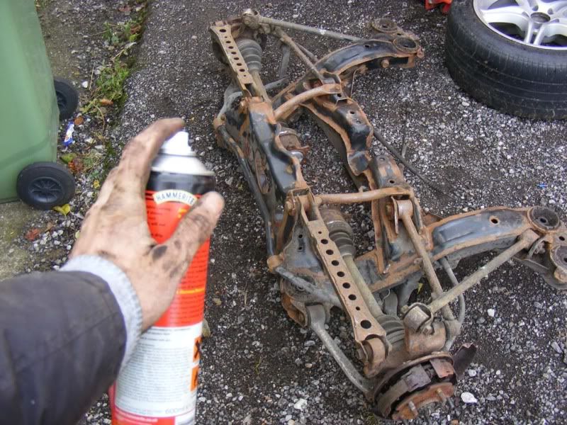
Step 49 - You can paint with a brush but because the subframe's quite a complex shape I would recommend a spray, give a good coating, it doesn't need to look amazing (unless you're making a show car) so you can get away with quite thick coats
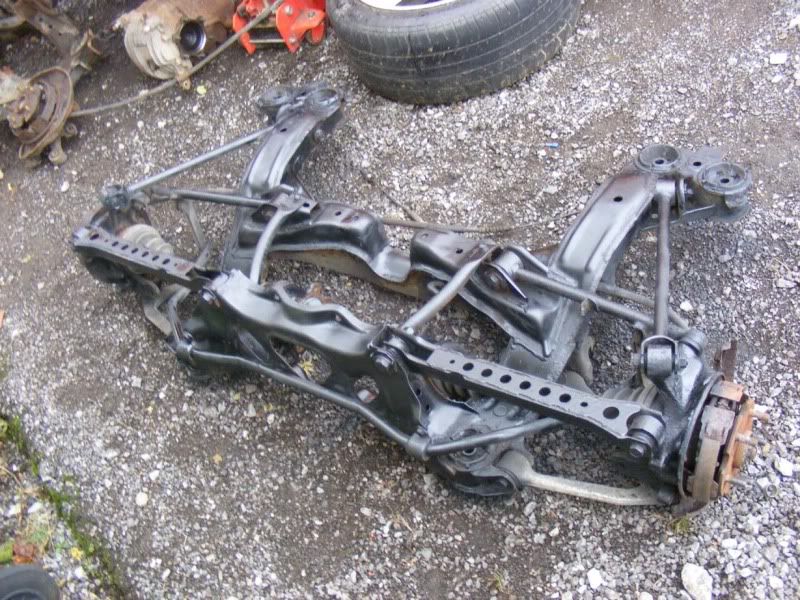
Step 50 - The end result. Note you should normally mask off any areas you don't want to spray but I was in a hurry!
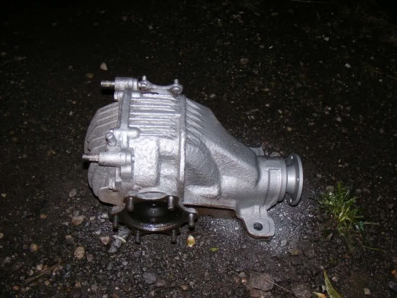
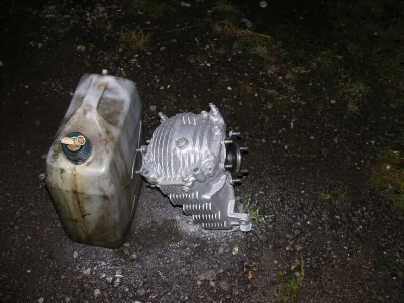
Step 51 -You can do the same for the diff ...
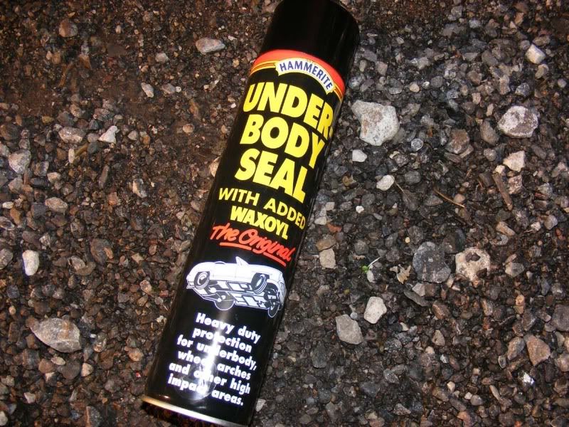
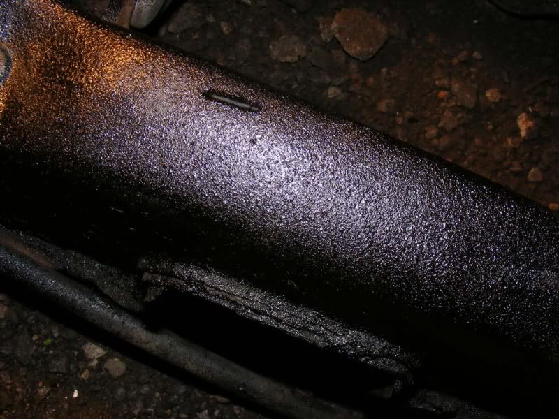
Step 52 - Once dry, flip the frame over and do the other side. The last two pictures shows a product I used, it's hammertie and waxoyl together so two good products and it works very well. It leaves a rough finish as shown in the last picture but can splatter quite a bit so regularly clean the cap
Step 1 - OK, continuing on from removing the subframe there is now a heck of a lot to strip down. There's more work in the strip down than in removing it! There are 2 14mm bolts holding the caliper carriers on, remove these then remove the carrier with pads and clips
Step 2 - Back to the usual 3/4" (or 19mm) socket and breaker bar so you can crack off the wishbone (upper arm) bolts and get them turning
Step 3 - Once slackened, use a spanner (or another socket) to hold both sides of the nut/bolt and remove completely
Step 4 - Remove the 17mm nut holding the wishbone to the hub via the balljoint. To test a ball joint, rotate it in all orientations, it should be a smooth feel ant not get stuck in any places. If the boot is split you will need to sort it
Step 5 - Once you have removed the nut, screw it back on the threads a couple of turns
Step 6 - Replace the 17mm socket (preferably an old one) and give it a firm smack (be brave, tapping it will do nothing) with a lump hammer, this should pop your ball joint off easily. The shaft below the threads is tapered so it is tight against the hub.
Alternatively get a ball joint splitter (two types, one with a bolt you tighten that I recommend because it won't tear the boot of the ball join and one which is like a 2 pronged fork which work but often damage the rubber boot).
Step 7 - Remove the nut once the ball joint is free and your wishbone should pull away (you may need to use a pry bar to encourage the bushes to pop out their mounting points but usually a wriggle will suffice)
Step 8 - Now we have to remove the stabiliser bar (anti-roll bar) stabiliser link (drop link). This is a double-ball joint affair and can be a bit of a pain. There are two 14mm nuts to remove and if you're lucky they will undo without spinning the balljoint (picture 1). If they don't then you can put a 2 pronged balljoint remover down and apply a little leverage which should be enough to stop it from spinning (pictures 2 and 3)
If they are really stubborn, just knock the link of its ball joint with a pry bar/chisel/flatblade screwdriver to expose the ball (picture 4) and then grab the ball joint with mole grips and remove that way (picture 5)
Step 9 - You can move on to the rest of the anti roll bar now - there are two brackets (pictures 1 and 2) that hold it to the subframe, each has two 12mm bolts. Remove all 4 bolts and the rollbar drops away (picture 3)
Step 10 - Next the diff, it's a big piece of what you have removed and has some hefty fasteners attached, we're back in the 3/4" realm again. Start with the two nuts at the back of the subframe as shown in the picture
Step 11 - Next get the two underneath, you can't see them in the first picture so I took another to show you the big bolts you are removing
Step 12 - Now jack things up again a little to give you some room to work and move to the front of the diff where the prop attaches. You have two bolts (each with a washer too) to remove here
Step 13 - Now we have a little bit of ingenuity! I advise you crack off all the driveshaft nuts BEFORE you remove the prop and then you won't need to do this bit but seeing as I didn't I will show you how to deal with it!
The driveshafts will rotate freely now so you can easily wedge something (in my case an extension bar for a 1/4" drive ratchet) between the subframe and the flange where the driveshaft meets the diff. Simply rotate the driveshaft/diff flange until it makes contact with the bar and holds it against the subframe then you can apply force to the nut without it just spinning.
Step 14 - Do this a number of times until you've removed all the nuts and washers too (you may not see them under the dirt but they are there, don't lose them!)
Step 15 - Once you have removed all the nuts you can use the CV (constant velocity) joint's flexibility to pull the shaft away from the diff
Step 16 - This is how I wedged the other side
Step 17 - When you have finished, simply lift the subframe up (from the front) and it will peel away nicely leaving you a diff on the jack. The subframe still ways a bit on its own so be careful and use two people if possible
Step 18 - Now the diff's out the way we'll finish removing the two hubs and driveshafts from the subframe. We’ll start with the hub, remove the rubber inspection bung with a flatblade screwdriver and look after it (they always go missing!)
Step 19 - Rotate the hub (which may be very difficult to do) until you can see the cog for the handbrake adjuster which is at the bottom when everything's the right way up! Use a torch to help you with this
Step 20 - Insert a flatblade screwdriver and rotate the cog upwards i.e. put the screwdriver in so it points at the floor then push the handle down so the tip finishes pointing at the sky, this will slacken off the handbrake shoes. The picture shows the adjuster wheel you are moving inside the hub
Step 21 - It can still be a real pain to get discs off and there's no substitute for a massive hammer. I have never warped or fractured a disc and I've hit some blooming hard I can tell you! There is a gap in the backing plate for the disc which is ample big enough to give a big hefty blow with a very big hammer (hammer shown in picture 2 along with the hub just after the disc is removed). Follow through with one single good blow and the disc should drop away as shown in picture 1
Step 22 - The driveshaft is still inserted in the hub so we better get rid of that now. Again a large hammer usually does the trick (although you can use pullers if preferred), give a sharp blow square on the end of the shaft and it will pop into the hub nicely (picture 1). Then use a suitable drift (extension bar again for me) to tap the shaft out (picture 2)
Step 23 - Now remove the 12mm nut holding the handbrake clamp onto the subframe (picture 1), this will then bend open (picture 2) allowing you to free the handbrake cable from the restraint and remove the metal clip altogether (picture 3)
Step 24 - 3/4" socket and a breaker bar against a spanner can be used to detach the 'number 2' lower suspension arm from the hub
Step 25 - Go to the inside of the subframe to remove the second nut on the lower suspension arm, this is one with a cam on it to adjust your suspension geometry so mark it up if you intend to put this back together. Once you've got the nut off, smack the bolt with a hammer to push it out and hope it doesn't snap!
Again, tap out with a drift of some sort. Once you've pushed the cam proud of the subframe you can use a lever to encourage it out, I went for the trusty ball joint splitter again (picture 2). Heat can sometimes help with stubborn bolts, if you go down this route then hold a blow torch on for a good minute then have a stab at it.
Keep those camber bolts safe, they cost about £10-£15 each from Toyota
Step 26 - With both bolts removed, use a pry bar to ease the lower arm out as shown
Step 27 - Next is the strut rod that is another connection between the subframe and hub. There is a long bolt going through the subframe which you need to remove (picture 1), and then a u joint on the hub which is a socket/spanner affair shown in picture 2 (all the normal 3/4"). Again, use a pry bar to ease the bar out the joints
Step 28 - With both bolts removed, pull the strut rod clear
Step 29 - Next is the 'number one' lower suspension arm. On the subframe end remove the nut and cam (mark if appropriate) as shown in the first picture. Give the bolt a firm smack to remove (picture 2). Then use a drift to knock the bolt all the way out (you can see it has just popped out onto the driveshaft on the third picture)
Step 30 - The other end of the lower arm is connected to the hub via a balljoint, remove the nut and hammer out (refit the nut first unlike shown in the picture!!)
Step 31 - With all that disconnected you are just about ready to pull the hubs away, simply rotate the handbrake cables so the barrel and cable line up with the cut out in the equaliser bar and they slide out. This will allow you to pull the cables through the subframe and separate the hub
Step 32 - There's another two stabiliser bars on the subframe which are simply two 3/4" nuts then they drop away as shown
Step 33 - Don't forget to pop the exhaust hanger off either!
From here you can disassemble the diff, driveshafts and handbrake shoes. I'll pop some pictures up if I do any work on these in the next few weeks
Following on from here we need to strip the handbrake assembly off the hub, this consists of two pads, an adjuster, a few springs and some collets and pins.
Step 34 - Rotate the hub until the cut-outs line up with one of the collets
Step 35 - You now need to push the collet down to compress the spring underneath it, this will allow you to twist the collet through 90 degrees so that the pin will release it through the cut outs. If you can do it by hand this is easiest, failing that you can try using a socket or a pair of pliers. Note you may need to hold the pin in from the back of the hub which is shown in the second picture
Step 36 - Once you have rotated the collet, it will pull away from the hub and you should take the spring with it. It's a bit tricky the first time you do it but after a while they're no problem
Step 37 - Now remove the pin guide, this simply lifts away. Note there are at least two types as shown in the pictures, the one shown in pictures 1&2 were off a JDM 92 and the third picture is from a 90 UK car
Step 38 - Free the pins from the hub, one side pushes straight out and the other is cranked (See second picture)
Step 39 - Onto the 2 main springs now, either use pliers or a screwdriver to unhook them from the hub - they will require quite a bit of pressure. Once they are off the centre pivot, simply unhook them from the handbrake shoes
Step 40 - Now the shoes will open up and pull down off the hub as shown
Step 41 - The handbrake cable needs to be removed by pushing the spring back and then forcing the cable down so that it can slide out of the mechanism as shown
Step 42 - You will probably have left the bar and spring behind as shown, remove from the hub
Step 43 - Here's the complete assembly for reference
Step 44 - The final thing you may need to remove is the handbrake cable which has splayed legs that come through the hub, push them in with a flatblade screwdriver whilst pulling the cable from the back of the hub. It's a little bit fiddly but take your time and it's not too bad
Step 45 - Now we're onto clearing up the frame itself, start by brushing off any loose debrit and dirt
Step 46 - Now use a drill with a wire brush attachment to go over the whole subframe. You can do this as many times as you like to get a good finish
Step 47 - When you've finished you should have something like this
Step 48 - Give it another brush over before painting to get rid of all the dust
Step 49 - You can paint with a brush but because the subframe's quite a complex shape I would recommend a spray, give a good coating, it doesn't need to look amazing (unless you're making a show car) so you can get away with quite thick coats
Step 50 - The end result. Note you should normally mask off any areas you don't want to spray but I was in a hurry!
Step 51 -You can do the same for the diff ...
Step 52 - Once dry, flip the frame over and do the other side. The last two pictures shows a product I used, it's hammertie and waxoyl together so two good products and it works very well. It leaves a rough finish as shown in the last picture but can splatter quite a bit so regularly clean the cap