Fuel pump rewire diagram

isnms

United States of America
Mar 30, 2005
2,145
0
36
Oklahoma
i80.photobucket.com
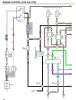
How would this do for a fuel pump rewire.

I'm going to go with the MKIV pump which draws a lot more amps. If I'm right, I will be able to keep the low voltage feature. Also, I can keep the relays in the engine bay and just run one 10awg power line to the pump.
[thumb]http://i80.photobucket.com/albums/j187/isnms/Supra/rewire_relays_fp.jpg[/thumb]
p792419_1.gif
 
Last edited:
Oct 11, 2005
3,819
20
38
Thousand Oaks, CA
That will work. A potentially more elegant solution is to get the MKIV fuel pump control computer ($230 new from Toyota). It accomplishes the same thing but in a single box.

This is something I've been pondering for a while. I'll be interested to hear how your install goes.
 

Attachments

  • mkiv-fuel-pump-control.jpg
    mkiv-fuel-pump-control.jpg
    103 KB · Views: 62

isnms

United States of America
Mar 30, 2005
2,145
0
36
Oklahoma
i80.photobucket.com
Yeah, that's the pump low speed path. The pump is at the end of the red wire.

The blue B+ and FP are equivalent to check connector B+ and FP since the stock wiring harness is not in use any more. If you need to run the fuel pump for testing you connect those together.
 
Last edited:
Oct 11, 2005
3,819
20
38
Thousand Oaks, CA
The question would be whether the 0.7ohm resistor from the MK3 pump circuit will work with the heavier current draw from the MK4 pump. You are looking for 9V at the pump in low-speed mode. It is possible the MK3 resistor will drop too much voltage and the pump will bog. I suppose the best plan is to try it and measure the terminal voltage.