Boost gauge installation - wiring query!!

supra1

Supraholic
Oct 19, 2007
58
0
0
EwwK
ok guys.
I removed the stock boost gauge and have installed an Autogauge one in its place (after some customising of course)

p850017_1.jpg


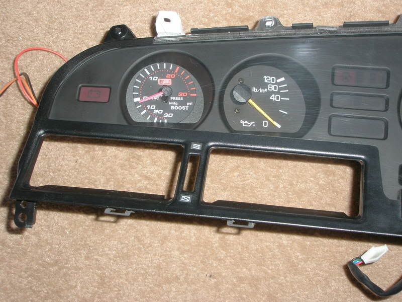
Anyway, ive installed this exact gauge (autogauge smoked gauge with 3 wires) on 2 cars before and it was easy.

But Im getting a problem with this one.
basically, no matter how I wire it up, the gauge light is coming on all the time...
and its really starting to annoy me :icon_mad:

This is how its setup.
Colours as per the tech sheet are:

orange - connect to good 12 v lighting

Black - connect to good ground

Red - 12v ignition switch

and as far as I can see all these are done!
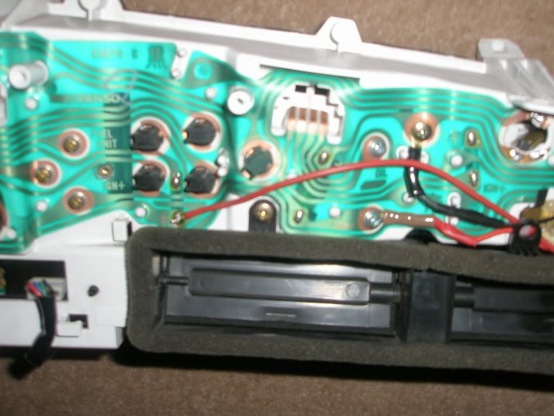
The Black is connected to the ground of the original OEm boost gauge.
The live is connected to the live of the original OEM boost gauge

and the orange lighting feed is connected to where the bulb went for the OEM boost gauge :1zhelp:

I have tried it on both sides of the bulb holder and it makes no difference.
I have removed it (the orange wire) and the boost gauge still stays lit!

I have moved the black wire to a different ground/earth and the same thing is happening?

Can anyone give me any advice on this please


p850017_2.jpg


p850017_3.jpg


It will be much appreciated :)
thanks
 

bustedknuckle

New Member
May 30, 2006
32
0
0
North Jersey
Just a guess, but if your orange wire is a control wire and wants to be connected to your dimmer or an equivalent point on the cluster which varies brightness you can use a 12v icepick light or voltmeter to check the correct side of the dimmer (potentiometer)to place it.Hope it helps a little.Trick is to read the schematic that came with it.
 

supra1

Supraholic
Oct 19, 2007
58
0
0
EwwK
bustedknuckle said:
Just a guess, but if your orange wire is a control wire and wants to be connected to your dimmer or an equivalent point on the cluster which varies brightness you can use a 12v icepick light or voltmeter to check the correct side of the dimmer (potentiometer)to place it.Hope it helps a little.Trick is to read the schematic that came with it.

Thanks!

Ive just had a nasty little feeling, that maybe this gauge is lit all of the time?
Being a smoked gauge and all of that? :naughty:

It is only coming on when the ignition is turned on..... So thinking on to past ones, maybe it is always lit no matter what?!
time for a new gauge i think :aigo:
 

hellraiser456

New Member
Dec 29, 2006
130
0
0
canada
hmm..i don't know why they would use three wires for a light bulb...but you should be able to get it to switch. if you take power from the gauge the light should turn off.
you mistake is the the wiring.

i think if you just want the light to come on when the lights on the dash come on...you should just connect the orange wires and red wires...and connect them to a light source. I installed mine into the dash like yours...but i used the cig lighter light as my power source. I used that because i didn't wanna solder that day. But my gauge has only two wires.

So if you combine the two(red and orange)...that should allow the relay to switch...and the red to gain power at the same time. This will only work however if your gauge only uses the power for the light. Just make sure you don't connect it backwards.
 

p5150

ASE and FAA A&P Certified
Mar 31, 2005
1,176
0
36
Central Idaho
Mechanical boost gauge FTL.....

But seriously - I think that your gauge uses the red as a primary power source and the orange as a switch input for the relay to turn the illumination on. I dont think you have the option for dimming the light but I could be wrong.

If you look at the wiring diagram for the illumination system on the supra it is not a basic potentiometer circuit like most cars. The lights are wired into the circuit in parallel and the current is controlled by a rather complex dimmer control unit. The control unit's green wire has a constant 12v and the white/green wire has opposing voltage that INCREASES as you DIM the lights. Yes I know it sounds wierd but since the w/g wire current changes with the movement of the dimmer switch some people wire it up to this one in hope that the gauges will dim with the dash light but they end up being the exact OPPOSITE. The aftermarket gauges will brighten but the cluster will dim and vice versa.

Supra Illumination Illustration

Since current is simply a product of difference in electrical charge between two points, the bulbs intensity changes when the circuits' current differentiation between the green and w/g wires are at the peak (when the w/g wire is at the LOWEST voltage because the green wire is a 12 v constant)

I am having a similar issue with aftermarket gauges and I am refusing to install another rheostat to control them separately. I am planning on removing the stock dimmer controller and installing a standard rheostat-based dimmer unit with one end to ground and the other end to w/g. These can be found very easily in all sorts of different toyotas from the 90s. The Green wire to the dimmer will be capped. (dont be fooled by the way it looks in the link. The color is wrong in the TEWD on pg 62. The Green wire looks Green w/white stripe in the pic)
 
Last edited:

supra1

Supraholic
Oct 19, 2007
58
0
0
EwwK
Thanks guys for the input.

hellraiser//

thanks

Can anyone else confirm this would work?
Im pretty sure the gauge only uses power for the light.

Are you saying I should solder both red and orange to the same light source? for example where the orange wire is soldered currently? to add the red wire to that contact as well?

p5150

Thanks for that useful info.
I think I will tackle the dimmer issue in due course.
I would be happy right now just to get the gauge light switching on with the headlights :biglaugh: , and once I have that working Im going to source another rheostat based dimmer and use that instead so that it works on the dimmer as well. :)
 
Oct 11, 2005
3,819
20
38
Thousand Oaks, CA
The dimmer is functionally identical to the old style rheostat, but implemented in a solid-state circuit design.

The green wire that goes to the dimmer is there to supply power to the active dimmer switch internal circuitry.

As noted, the W-G wire is effectively connected to a constant current source on the dimmer, the value of that current being set by the dimmer control dial. Less current, dimmer lights.

I would suggest disconnecting the wiring and doing some trouble shooting on the bench to see which wires really control the illumination. Is there no circuit diagrams with the gauge docs?
 

p5150

ASE and FAA A&P Certified
Mar 31, 2005
1,176
0
36
Central Idaho
3p141592654 said:
As noted, the W-G wire is effectively connected to a constant current source on the dimmer, the value of that current being set by the dimmer control dial. Less current, dimmer lights.
May be a different way of phrasing it, but when MORE current comes from the white/green wire the lights get dimmer. Put a multimeter on the w/g wire and you will see what I mean. This translates to less current flow across the bulb. When there is less current on the w/g wire, the cluster actually gets brighter because of the difference in voltage between the green wire (12v constant) and the w/g wire (varies with dimmer).

We are probably saying the same thing in a different context.
 
Oct 11, 2005
3,819
20
38
Thousand Oaks, CA
Your observation and explanation are correct, but the way it was explained suggests you may not be "skilled in the arts", as our patent attorney would say. Please don't take that as an insult, I just mean you are not an electrical engineer by training.

Ask any EE and the response will be its a controlled current source.
 

supra1

Supraholic
Oct 19, 2007
58
0
0
EwwK
This may not be an option on many aftermarket gauges though after looking into it, even with a standard rheostat dimmer, because most LED drive circuits now use a voltage/current limiting device which drives the LED illumination at 2 set rates - and this will not alter with a rheostat or regulator based illumination dimmer.

These Car dimmers are also set up to deal with standard lamps, these take little change in current to make them dim. Because an LED is much less of a current draw, a change in current that has an effect on a bulb will have little/no effect on an LED I dont think?
 

supra1

Supraholic
Oct 19, 2007
58
0
0
EwwK
Does anyone know a link to a wiring diagram for the actual dash clock PCB?
Would be really useful for some other plans I have for gauges!
thanks
 

buldozr

New Member
Jan 9, 2007
362
0
0
North Texas
sounds to me if you cut the red wire, It will work the way you want it, I might be wrong though...:icon_bigg get the multi meter out and check continuity of the bulb, find out which wire is for the physical bulb, (red or orange, sounds like orange is your man though) sounds like for whatever reason this gauge has an extra wire??? cut the red wire and see what happens. Nice gauge btw. Good mod, you have the right idea for sure.
 

supra1

Supraholic
Oct 19, 2007
58
0
0
EwwK
buldozr said:
sounds to me if you cut the red wire, It will work the way you want it, I might be wrong though...:icon_bigg get the multi meter out and check continuity of the bulb, find out which wire is for the physical bulb, (red or orange, sounds like orange is your man though) sounds like for whatever reason this gauge has an extra wire??? cut the red wire and see what happens. Nice gauge btw. Good mod, you have the right idea for sure.


Hmmm!
Not sure on this advice as the red wire is the main feed :biglaugh:
But thanks for the input dude :icon_bigg
 

Jaguar_5

It's ALIVE!
Feb 7, 2006
1,468
0
0
Seattle
Personally, I would rewire it, I don't know if it's such a good idea to use the stock cluster's pcb for your wiring, I've heard of it being overloaded and burning out traces before...
 

buldozr

New Member
Jan 9, 2007
362
0
0
North Texas
supra1 said:
Hmmm!
Not sure on this advice as the red wire is the main feed :biglaugh:
But thanks for the input dude :icon_bigg

just knowing common aftermarket radios and what not, the orange wire is always the illumination wire to be routed for the dimmer, like I said, I could be wrong.

edit: even more interesting, all of the mechanical gauges I have were a common two wire install, one power, one ground, why would their be a third wire.... its not like the gauge itself has a relay inside... makes no bloody since. get the multi out.
 

supra1

Supraholic
Oct 19, 2007
58
0
0
EwwK
Jaguar_5 said:
Personally, I would rewire it, I don't know if it's such a good idea to use the stock cluster's pcb for your wiring, I've heard of it being overloaded and burning out traces before...


I agree, that would be the best option!
But I dont have a wiring diagram for the PCB or clock wiring at present (or should I say I cannot find it on TSM) and I have a spare set of clocks in mint condition (with PCB) so I am taking this route initially at least :icon_bigg

With that said, I know of several people who have modded the PCB like this and had no trouble at all...
I think it would be more of an issue if I installed like 3 or 4 extra guages off the stock PCB. This, I believe, would be asking for trouble :biglaugh:
 

p5150

ASE and FAA A&P Certified
Mar 31, 2005
1,176
0
36
Central Idaho
3p141592654 said:
Your observation and explanation are correct, but the way it was explained suggests you may not be "skilled in the arts", as our patent attorney would say. Please don't take that as an insult, I just mean you are not an electrical engineer by training.

Ask any EE and the response will be its a controlled current source.

Yeah - I guess you could say that im definately not that skilled in the arts. I could tell you have some background in the subject for sure! Honestly, I couldnt begin to tell you how that damn dimmer works piece by piece.

What do you think about wiring a traditional rheostat like I am planning to in place of the stock dimmer control unit? Do you think it will pull too much current through the illumination circuit and burn out the lights?
 

supra1

Supraholic
Oct 19, 2007
58
0
0
EwwK
buldozr said:
just knowing common aftermarket radios and what not, the orange wire is always the illumination wire to be routed for the dimmer, like I said, I could be wrong.

edit: even more interesting, all of the mechanical gauges I have were a common two wire install, one power, one ground, why would their be a third wire.... its not like the gauge itself has a relay inside... makes no bloody since. get the multi out.

You are right with that.
Thing is this gauge doesnt have dimmer sadly :( (and nor do any other stock ones **unmodified** that I am aware of?)

I dont get this part either!
I would understand completely if

1/ you turned the key and the gauge came on dimmed
2/ you put the lights on and it got brighter

but as far as I can tell (I am working in a garage with no mains electricity so at night Im relying on various 12v lighting sources!) the light stays the same.
With that said I could have missed the change in brightness and this would mean that the orange switched lighting wire was indeed working?

Anyway, I did as suggested and joined the red and orange wires on the old lamp terminal. *THANKS to the poster who suggested that*
and BINGO!!
The gauge is now illuminating on the lights only.
On ignition it remains dimmed like the other clocks which is what I wanted :biglaugh:

One small issue though, and I dont know if this was present before I took the clocks out!?
but the rear tail light out/brake light out (not sure which its meant to be) warning lamp is staying lit?

Both tail lights and rear brake lights are working 100% as I tested them. But I have not had the engine running and pressed the brake pedal yet as some other bits are off the car as Ive been installing a new alarm.

I have had a car in the past (audi) that required the engine running and brake pedal pressed to run a *system check* and then the warning lamp would go out.

is it the same on the Supra or do I have a problem here :1zhelp:

Things like that REALLY bug me and it will have to be fixed! which is very annoying if this is a fault because its about -10 outside right now :biglaugh:

Suggestions on a 'post' card please guys!
thanks