cylinder head porting theories... and such

Toy88T

New Member
Apr 27, 2005
10
0
0
USA
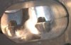
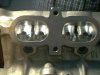
IJ - Thank you so much for the detailed cutaway of a 7M head! Awesome! Is there any chance that you can show one with the cut right down the middle of both the intake and exhaust ports? Or am I not seeing it from the posted ones? Trying to see how the ports are configured from a side view, so that I can do a better porting job without messing up too bad.

Halsupramk3 - Just wanted to say "Thank you" for the detailed email of porting the 7M head.

Cheers!
 

IJ.

Grumpy Old Man
Mar 30, 2005
38,728
0
0
61
I come from a land down under
Toy88T: That slice is right through the middle of the combustion chamber and both ports!

It's a 4 valve head so the ports siamese.

What you can see in the pics is half a port at the divider.

I'll take some more pics a little later today and DrJ will have some high res ones on Mk3Tech.

I Didn't want to cut through the Valve seat for a few reasons.
1: It's sort of evident where you need to smooth the valve bowl and remove the undercuts if you put your finger in and have a feel ;)!

2: Taking more material from there is counter productive as the valve seat is the restriction remembering that the valve is in there and only opens at best 10 mm (fairly bug cam needed for this stock is more like 7.5mm)

3: The new blade in my big bandsaw is Aluminium only and only has 7 teeth per inch so won't cut Steel without shedding teeth! (not to mention it's an $80 blade)
 

flubyux2

Madd Tyte JDM yo ®
Apr 2, 2005
1,019
0
0
42
st. pete, fl
www.myspace.com
wow, nicely done 1J!

thats a great load off me mind.

so right now, theres no chance of getting a crosscut of the head right at the center of the port/valve opening?

that helps alot, but id also like to see how much room there is at the valve bowl behind the valve.
 

IJ.

Grumpy Old Man
Mar 30, 2005
38,728
0
0
61
I come from a land down under
Flub: next time I'm buying tooling I'll get a steel blade and see what I can do!

Personally I won't touch much in the bowl just smooth it out and blend any edges.

The only place where it's going to make a difference is on the short turn radius anyway and it's already pretty well done from the factory.

Many years ago I did a bit of flow bench testing on SBC's and got a bit of a "feel" for what gives results and what is a waste of time ;)!
(boy some of my early port work was a HUGE w.o.t!)
 

Boostedstr8six

I have better SA than you
Mar 30, 2005
401
0
16
Near Columbia, the river
Thanks IJ. :bigthumb:

Would any of you be so kind as to highlight the areas (on IJs cut-away pics) that could benefit from some work? I've read tons of conversations about what people have done but I can't visualize it too well. Either photochop or physically marking the casting?
 

IJ.

Grumpy Old Man
Mar 30, 2005
38,728
0
0
61
I come from a land down under
Boosted: See the 2nd pic,

See where the exhaust gasket mark is?

I'd take the ports out to that then continue it in untill the roof of the port thins out.

I'd take the floor in the same amount so you don't make the short turn radius too sharp then carefully blend the bowls into the valve seats which in mine will be bored out 1 mm for the bigger valves.

Then I'd increase the port size in the exhaust manifold to keep the reversion dam (Manifold Port bigger than Head port)

On the intake I'd just clean and blend and remove bugger all as our ports are very well designed to begin with.
 

flubyux2

Madd Tyte JDM yo ®
Apr 2, 2005
1,019
0
0
42
st. pete, fl
www.myspace.com
i think that the meat behind the valve seats should be opend up a little bit. add some more volume and smooth the radius in the throats. also, itd probably help to smooth out the roof of the port as well as the valve guide. i think that a slight recess should be added to the sides of the port closest to the cylinder walls, this would change the 7M into a swirl port setup... something i picked up from a Formula1 engine builder.
 

DEFIANT 7M

101MM stroke of INSANITY!
Mar 30, 2005
620
0
0
55
Nashville/Miami
flubyux2 said:
i think that the meat behind the valve seats should be opend up a little bit. add some more volume and smooth the radius in the throats. also, itd probably help to smooth out the roof of the port as well as the valve guide. i think that a slight recess should be added to the sides of the port closest to the cylinder walls, this would change the 7M into a swirl port setup... something i picked up from a Formula1 engine builder.

Exactly ;)
 

Halsupramk3

Member
Apr 4, 2005
444
0
16
Mississippi
Thanks for that extra pic. Can you clean the intake out some please. It is difficult to see the directions the air would flow because the walls are difficult to define when they are black in the pics.

I think the intake can be rounded out to flow smoother at the turns to the intake valve. The roof of the port looks like it has some sharp turns in it. It may just be the pic tho. You could do this just slightly and still make sure the port is getting smaller as it approaches the valves. There is enough wall between the water jackets to be sound. I need to find a junk head because there are a lot of ways i would like to slice up a head.
 

IJ.

Grumpy Old Man
Mar 30, 2005
38,728
0
0
61
I come from a land down under
Hal: Very welcome!
If I get time during the week I'll chuck it in the beadblaster and take a few more pics.

I tend to be conservative with port work as it's easy to remove material but a pain in the arse to put it back!

I'd be interested to see a pic or a drawing of what Flub is talking about though!
(If D7M Think it's a good idea it must be cos those NA guys don't have the HP screw!<boost controller> :) )
 

Halsupramk3

Member
Apr 4, 2005
444
0
16
Mississippi
Just removing the ridge under the valve seat will help out a lot. It is easy to do to. See the first pic where the seat on the right is done and the seat on the left is stock. The casting line on the sides of the ports is also smoothed away. See the second pic. It did not take much work to do this. Just be sure to do the same thing to each port in progression before moving on to the next step. Consistant work to keep them flowing equally.

Any time the head is off you could remove that lip/ridge under the seat. Porting increased low lift flow tremendously; over double.

Thanks for your efforts IJ.
 

Attachments

  • intake half roughedq2.jpg
    intake half roughedq2.jpg
    46.9 KB · Views: 56
  • intake port 80% doneq.jpg
    intake port 80% doneq.jpg
    102.9 KB · Views: 56

IJ.

Grumpy Old Man
Mar 30, 2005
38,728
0
0
61
I come from a land down under
Thanks for the pics Hal!

I just picked up a brand new head casting to use in my next build!

head9a.jpg
 

flubyux2

Madd Tyte JDM yo ®
Apr 2, 2005
1,019
0
0
42
st. pete, fl
www.myspace.com
so that ridge under the valve seat, is that PART of the valve seat or is it a ridge that is part of the valve bowl itself?

i would cut the valve seat and blend the bowl essentially. im just worried about nicking the valve seat margin where the valve actually seals against it. i would also cut back the valve guide bosses and thin them out a little.

and as far as adding the "rifling" to the port and valve bowl, its really hard to explain to someone who doesnt know. i havent personally seen it, but the engine builder explained it to me and i was able to understand what he meant. i guess if you just took you sanding roll on the end of your grinder, and just sanded a shallow recess/groove/ into the port in a spiral direction, youd have a swirl-inducing port.
 

IJ.

Grumpy Old Man
Mar 30, 2005
38,728
0
0
61
I come from a land down under
Flub: I use a ring of PVC conduit to protect the valve seat.

I sort of understand what you mean by rifleing the port, I'm thinking of building a primative flow bench and will try some theories on a junk head before attacking the new one!
 

Halsupramk3

Member
Apr 4, 2005
444
0
16
Mississippi
flubyux2

That ridge is created when the valve seats are pressed in. It is a small lump directly under the seat. You can feel it with your finger. Be careful inserting and removing any grinding bit in and out of the valve hole so as not to touch the seat. You can grind around this area and not touch any of the seat. I used and egg shaped double cut carbide tip. You can smooth this area out flush with the port walls.
 

flubyux2

Madd Tyte JDM yo ®
Apr 2, 2005
1,019
0
0
42
st. pete, fl
www.myspace.com
hey hal. yeah, the egg-shaped bit and the cylindrical bit w/ a round tip are my favorite grinding bits.

i usually am pretty good w/ keeping the grinding bit from nicking the valve seat itself... its the collet of the grinder that typically sneaks up and puts a scuff in the seat. thats what will most likely get me when i least suspect it.

id like to try to rig up a flow bench also. that way, when i get around to porting my heads, ill at least be able to compare before and after flow numbers, or at least pressure drop between the ports. then i can try to shoot for an even restriction between each port. if the restrictions are similar, then they will be close to flowing the same rate under the same pressures.
 

IJ.

Grumpy Old Man
Mar 30, 2005
38,728
0
0
61
I come from a land down under
Hal: Sorry it took so long!

Sort of interesting fact the new head casting I got #16 has the same size divider as the old head I have here #6 but the intake divider is almost non existant!

head5.jpg


head6.jpg


head7.jpg


head8.jpg
 
Last edited: