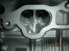
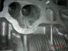
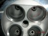
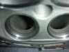
I posted this on clubna-t but I thought some of you guys could use it as well. This is the head of a 2jzge that im going na-t with.
First and foremost, I want to let everybody know that you should not change the basic shape of the port!!! REMEMBER THIS ABOVE ALL OTHER THINGS. I do not claim to be the allmighty head-porter. I dont even own a flow bench. However, I do not see a problem with anybody trying to clean up their ports a bit. Once you get to look at it you will see where the restrictions lie.
Read this and understand it before you start:
http://en.wikipedia.org/wiki/Cylinder_head_porting
If you have a flow bench then great - you probably already know all this stuff and more. This is designed for the beginner... I guess you can stop reading or just send me some critiques... I wont take it personal.
It is very easy to improve on some simple flaws in head design that are a product of mass production. You do not have to be an expert with a flow bench - just have a bit of patience and attention to detail. I will add some pictures later today!
With that in mind, I will guide you through some basic techniques and point you toward some resources you can use....
www.standardabrasives.com has some good tutorial information to start
1. PREPARATION: Before you start on your cylinder head, send it to a reputable machine shop to be inspected and cleaned. You dont want to put a bunch of work into a head that is warped or cracked. Tell them that you plan on doing some simple port work. Dont talk about it too much with them because they may try to talk you out of it - especially if they know a guy that does it. Trust me, it really isnt that hard. Additionally, the valve seats can be cut after you are done porting so you dont have to be as careful not to nick them. Same with the deck surface - it can be decked once the port work is done. (I like to use an old towel under the head just to keep the deck from being gouged.) Be sure you have a good core to start with.
If the valve seats have already been cut just put some duct tape on them and be careful not to hit them.
Acquire an air compressor, die grinder and a Standard Abrasives head porting kit $40 (or similar if you can find one). The kit is good because it comes with an assortment of grits and stones... Stay away from purchasing the metal rasps to do the port work because they just clog up and are junk very quickly. Be sure that the surface that you will have the head laying on is not going to gouge it.
2. PORT STENCILING: The first step to cleaning up your ports is called port matching - it is designed to remove any irregularities between the mating surfaces of the head and manifold.
DO NOT PORT MATCH YOUR EXHAUST MANIFOLD TO THE HEAD. ONLY PORT MATCH THE INTAKE MANIFOLD. PORT MATCHING THE EXHAUST MANIFOLD TO THE HEAD REMOVES THE REVERSION DAM AND CAN HURT YOUR PERFORMANCE.
Ideally, you want the interior of the joint to look and feel smooth (without transition). You can do this with the gasket that you are going to install - use it as a stencil so that the manifold and head have the exact same ports. Spray the mating surface of the head with a light coat of black rattle-can paint, let it dry a bit, align the gasket on the head, and be sure to hold the gasket perfectly steady as you scratch a line on the head with a scribe and trace the opening of the gasket.
4. CUTTING THE PORT OPENING - YOUR FIRST STEP: As you begin to cut into the head with the rotary STONE, ensure that you go slow and steady until you get the hang of it. If your die grinder is going too fast you will get aluminum buildup on your stone - too slow and it will not cut effectively. To clean off the stone when you get some aluminum buildup you can just dip it in a small cup of spray lubricant and spin it a bit - I prefer the wal-mart cheap lubricant because it is only $1 per can and im a cheap ass. It works.
Do one section at a time. For example, cut the bottom section of every port opening with the stone, then flip the head over so that you can do the top section. Then, move to the port divider, the valve guides, and finally the short turn radius near the valve. Repeat for each successive grit. Dont try to do each port completely one by one. Uniformity is key, and accomplishing it section by section will allow you to keep the ports as similar as possible. It will also minimize the amount of bit changes you will have to do and save you time.
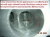
Start by cutting the edge of the port to the line you have scribed and then blend your way into the port about an inch or so. You arent really ENLARGING the port, only shaping the sections inside the scribed line so that the manifold and head match. Keep any venturi (plural) that you find intact and dont create venturi or widen the port in places that arent already in the casting. If you dont know what a venturi is read this: http://en.wikipedia.org/wiki/Venturi
I have noticed two venturi - one on the intake manifold right before the injectors and one at the valve.
Remember to KEEP THE BASIC PORT SHAPE. Port shape is more important than making the entire thing perfectly smooth. Dont try to grind out every little imperfection - you will only screw your flow because you will have an irregular port diameter....
As you cut to the line you scribed, make a nice transition from the opening to the interior walls. Remove any sharp edges on the interior of the port. When shaping and rounding off edges (like the top of port and short turn radius) be sure to move the stone around to avoid sharp edges - you will get the hang of it.
DONT TRY TO GET IT PERFECT WITH THE STONE. KEEP IN MIND THAT YOU WILL STILL REMOVE SOME MATERIAL WITH THE 40 AND 80 GRIT CARTRIDGE ROLLS.
Once you have completed the bottom half of all six intake ports, flip the head over and clean up the top half. Remember to rinse your bit with some lubricant in a cup to clean off the aluminum if you need to.
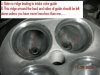
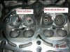
After the port openings are complete, position the head so that you can easily access the port divider. Grind each side bit by bit (alternate regularly) until the divider has sharp leading edge. The edge should remain centered and not tapered towards either side. Remember, as before, that this is not the last step and that you will still be using the 40 and 80 grit rolls. You dont want a "knife" edge yet; use the 80 grit roll for that on the last step.
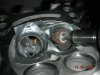
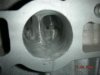
Next, grind the valve guides down until the outside edge is flush with the intake wall. Leave the back of the guide so that it is the same height as the port wall on the inside edge. You will have a gap around the sides and back of the guide, but without a flow bench and some testing on a junk head it is difficult to say what additional material you should remove. The gap is something you will have to live with. You COULD remove some more material from the port to make it smooth, but I have no idea what this will do for the flow because you will be opening up the port more..... I honestly dont think this is a good idea. Keep it simple and dont molest it TOO much.
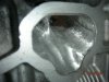
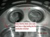
Next, access the port from the side of the combustion chamber. Before you start, feel the short turn radius with your finger. It is the part on the bottom of the port that joins the valve opening with the port. (Look at the wikipedia illustration) This is where you will make most of your gains. You dont want to hog this out - remember the venturi idea? You have a venturi at the valve opening. Simply cut down the sharp edges to remove turbulence and provide more of a direct shot for the airstream into the combustion chamber. DONT wallow out the ports and remove the venturi.
If any large steps are present from the port to the valve seat you need to smooth them out. It usually looks like a straight bore was used before the seats were installed because there is a sharp edge on the transition to the combustion chamber. Rough in a nice smooth rounded edge where needed with the stone - remember that the 40/80 grit will be used later to finalize it.
5. 40/80 GRIT CARTRIDGE ROLLS - SMOOTHING IT OUT
You should have already completed MOST of the work with the stone bit. The rest of this goes really fast. In the same fashion as before - bottom of port, top of port, divider, guide and port body, short turn radius and valve seat - complete the remainder of the head in phases. Do all phases in 40 grit, then move to 80. I even went so far as to finish the intake ports with a 120 grit.
One subject of contention may be the final finish roughness of the ports. Some prefer a rougher texture to ensure fuel atomization. If you look at all other examples of surface texture, they are referring to TB injection or carburated applications. Since we have port injection, there is no way the fuel is going to collect on the ports in the head; especially at operating temperature. Personally, I would rather have a smooth surface for the port and runners; I use a 120 grit for the final. With a carburated or TB injected car I would probably leave it with a 40 grit finish.
When knife-edging the port divider dont try to do it all with the 40 grit - use the 80 grit to finish it. Make sure to alternate sides to keep the edge in the middle. Always remember that the goal is to remove as little material as possible to keep the basic port shape.
When blending the short turn radius and valve area, remember to avoid sharp edges. Keep the grinder moving and attack it from all different angles!
Your bare finger is the best detector of surface roughness and completion of the task - use it on the 80 grit step!
That wasnt so hard was it?
See the next post for my recommendations on exhaust ports and an explination of the pictures below.......
First and foremost, I want to let everybody know that you should not change the basic shape of the port!!! REMEMBER THIS ABOVE ALL OTHER THINGS. I do not claim to be the allmighty head-porter. I dont even own a flow bench. However, I do not see a problem with anybody trying to clean up their ports a bit. Once you get to look at it you will see where the restrictions lie.
Read this and understand it before you start:
http://en.wikipedia.org/wiki/Cylinder_head_porting
If you have a flow bench then great - you probably already know all this stuff and more. This is designed for the beginner... I guess you can stop reading or just send me some critiques... I wont take it personal.
It is very easy to improve on some simple flaws in head design that are a product of mass production. You do not have to be an expert with a flow bench - just have a bit of patience and attention to detail. I will add some pictures later today!
With that in mind, I will guide you through some basic techniques and point you toward some resources you can use....
www.standardabrasives.com has some good tutorial information to start
1. PREPARATION: Before you start on your cylinder head, send it to a reputable machine shop to be inspected and cleaned. You dont want to put a bunch of work into a head that is warped or cracked. Tell them that you plan on doing some simple port work. Dont talk about it too much with them because they may try to talk you out of it - especially if they know a guy that does it. Trust me, it really isnt that hard. Additionally, the valve seats can be cut after you are done porting so you dont have to be as careful not to nick them. Same with the deck surface - it can be decked once the port work is done. (I like to use an old towel under the head just to keep the deck from being gouged.) Be sure you have a good core to start with.
If the valve seats have already been cut just put some duct tape on them and be careful not to hit them.
Acquire an air compressor, die grinder and a Standard Abrasives head porting kit $40 (or similar if you can find one). The kit is good because it comes with an assortment of grits and stones... Stay away from purchasing the metal rasps to do the port work because they just clog up and are junk very quickly. Be sure that the surface that you will have the head laying on is not going to gouge it.
2. PORT STENCILING: The first step to cleaning up your ports is called port matching - it is designed to remove any irregularities between the mating surfaces of the head and manifold.
DO NOT PORT MATCH YOUR EXHAUST MANIFOLD TO THE HEAD. ONLY PORT MATCH THE INTAKE MANIFOLD. PORT MATCHING THE EXHAUST MANIFOLD TO THE HEAD REMOVES THE REVERSION DAM AND CAN HURT YOUR PERFORMANCE.
Ideally, you want the interior of the joint to look and feel smooth (without transition). You can do this with the gasket that you are going to install - use it as a stencil so that the manifold and head have the exact same ports. Spray the mating surface of the head with a light coat of black rattle-can paint, let it dry a bit, align the gasket on the head, and be sure to hold the gasket perfectly steady as you scratch a line on the head with a scribe and trace the opening of the gasket.
4. CUTTING THE PORT OPENING - YOUR FIRST STEP: As you begin to cut into the head with the rotary STONE, ensure that you go slow and steady until you get the hang of it. If your die grinder is going too fast you will get aluminum buildup on your stone - too slow and it will not cut effectively. To clean off the stone when you get some aluminum buildup you can just dip it in a small cup of spray lubricant and spin it a bit - I prefer the wal-mart cheap lubricant because it is only $1 per can and im a cheap ass. It works.
Do one section at a time. For example, cut the bottom section of every port opening with the stone, then flip the head over so that you can do the top section. Then, move to the port divider, the valve guides, and finally the short turn radius near the valve. Repeat for each successive grit. Dont try to do each port completely one by one. Uniformity is key, and accomplishing it section by section will allow you to keep the ports as similar as possible. It will also minimize the amount of bit changes you will have to do and save you time.
Start by cutting the edge of the port to the line you have scribed and then blend your way into the port about an inch or so. You arent really ENLARGING the port, only shaping the sections inside the scribed line so that the manifold and head match. Keep any venturi (plural) that you find intact and dont create venturi or widen the port in places that arent already in the casting. If you dont know what a venturi is read this: http://en.wikipedia.org/wiki/Venturi
I have noticed two venturi - one on the intake manifold right before the injectors and one at the valve.
Remember to KEEP THE BASIC PORT SHAPE. Port shape is more important than making the entire thing perfectly smooth. Dont try to grind out every little imperfection - you will only screw your flow because you will have an irregular port diameter....
As you cut to the line you scribed, make a nice transition from the opening to the interior walls. Remove any sharp edges on the interior of the port. When shaping and rounding off edges (like the top of port and short turn radius) be sure to move the stone around to avoid sharp edges - you will get the hang of it.
DONT TRY TO GET IT PERFECT WITH THE STONE. KEEP IN MIND THAT YOU WILL STILL REMOVE SOME MATERIAL WITH THE 40 AND 80 GRIT CARTRIDGE ROLLS.
Once you have completed the bottom half of all six intake ports, flip the head over and clean up the top half. Remember to rinse your bit with some lubricant in a cup to clean off the aluminum if you need to.
After the port openings are complete, position the head so that you can easily access the port divider. Grind each side bit by bit (alternate regularly) until the divider has sharp leading edge. The edge should remain centered and not tapered towards either side. Remember, as before, that this is not the last step and that you will still be using the 40 and 80 grit rolls. You dont want a "knife" edge yet; use the 80 grit roll for that on the last step.
Next, grind the valve guides down until the outside edge is flush with the intake wall. Leave the back of the guide so that it is the same height as the port wall on the inside edge. You will have a gap around the sides and back of the guide, but without a flow bench and some testing on a junk head it is difficult to say what additional material you should remove. The gap is something you will have to live with. You COULD remove some more material from the port to make it smooth, but I have no idea what this will do for the flow because you will be opening up the port more..... I honestly dont think this is a good idea. Keep it simple and dont molest it TOO much.
Next, access the port from the side of the combustion chamber. Before you start, feel the short turn radius with your finger. It is the part on the bottom of the port that joins the valve opening with the port. (Look at the wikipedia illustration) This is where you will make most of your gains. You dont want to hog this out - remember the venturi idea? You have a venturi at the valve opening. Simply cut down the sharp edges to remove turbulence and provide more of a direct shot for the airstream into the combustion chamber. DONT wallow out the ports and remove the venturi.
If any large steps are present from the port to the valve seat you need to smooth them out. It usually looks like a straight bore was used before the seats were installed because there is a sharp edge on the transition to the combustion chamber. Rough in a nice smooth rounded edge where needed with the stone - remember that the 40/80 grit will be used later to finalize it.
5. 40/80 GRIT CARTRIDGE ROLLS - SMOOTHING IT OUT
You should have already completed MOST of the work with the stone bit. The rest of this goes really fast. In the same fashion as before - bottom of port, top of port, divider, guide and port body, short turn radius and valve seat - complete the remainder of the head in phases. Do all phases in 40 grit, then move to 80. I even went so far as to finish the intake ports with a 120 grit.
One subject of contention may be the final finish roughness of the ports. Some prefer a rougher texture to ensure fuel atomization. If you look at all other examples of surface texture, they are referring to TB injection or carburated applications. Since we have port injection, there is no way the fuel is going to collect on the ports in the head; especially at operating temperature. Personally, I would rather have a smooth surface for the port and runners; I use a 120 grit for the final. With a carburated or TB injected car I would probably leave it with a 40 grit finish.
When knife-edging the port divider dont try to do it all with the 40 grit - use the 80 grit to finish it. Make sure to alternate sides to keep the edge in the middle. Always remember that the goal is to remove as little material as possible to keep the basic port shape.
When blending the short turn radius and valve area, remember to avoid sharp edges. Keep the grinder moving and attack it from all different angles!
Your bare finger is the best detector of surface roughness and completion of the task - use it on the 80 grit step!
That wasnt so hard was it?
See the next post for my recommendations on exhaust ports and an explination of the pictures below.......