
I've been getting this code 31 for a while and i bought a brand new afm... I've cleared the codes and it always comes back. I unplugged the connector and blew both connections out and cleaned them up and plugged it back in but it's still throwing the code... What's up with this?
Code 31 On a Brand New AFM?!?
- Thread starter chris89
- Start date
You are using an out of date browser. It may not display this or other websites correctly.
You should upgrade or use an alternative browser.
You should upgrade or use an alternative browser.
Because the code can also be caused by the wiring ")
This is the pitfall of throwing parts at a problem vs testing to determine cause. Unfortunately, considering this is a new AFM module, it was an expensive lesson.
This is the pitfall of throwing parts at a problem vs testing to determine cause. Unfortunately, considering this is a new AFM module, it was an expensive lesson.
So, the same as following the TSRM on Resistance between each terminal, But rather than on the AFM, Test the resistance on the AFM connector? Should the key be in the "ON" position? (engine not started, But electronics On). I have a question about this code. What kind of symptoms could this cause? I just blew out the connections, What would be a better more Effective way of cleaning?
Last edited:
You're talking about testing the AFM...the wiring will have to be tested from end to end to the ECU. Or do it in sections using a insulator piercing probe. I would do a visual inspection 1st by tracing the wire through the harness...very often the wire insulation is brittle/cracked where it crosses the top of the motor above the cam gears. Take a good look at the connector itself. Electronics cleaner will do a good job of cleaning the connector.
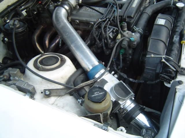
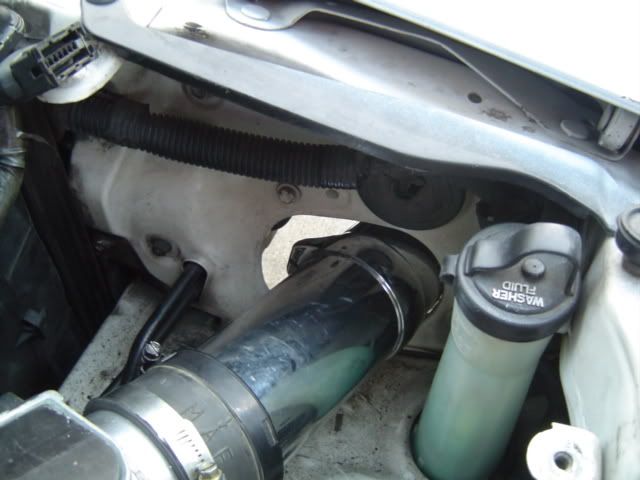
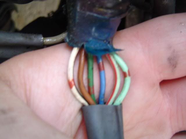
I took some pics and some videos... The idle is really screwy and it sounds like it's missing, but still drives fine. The gas milage is horrible, Seems like a lack in power, idle isn't smooth... also the ignition timing is screwed up... like it flucuates pretty drastically from about 15* BTDC and like 10* BTDC... that's with the distributer cranked all the way to the Retard side... when i put it close to the middle it goes way above 15* BTDC... but idles Smoother... I'll Test my AFM tonight or Tomorrow.
PICS
VIDEOS
#1
http://www.youtube.com/watch?v=g271J21JcWc
#2
http://www.youtube.com/watch?v=jaJS2BlZPMM
#3
http://www.youtube.com/watch?v=qxisq467F98
PICS
VIDEOS
#1
http://www.youtube.com/watch?v=g271J21JcWc
#2
http://www.youtube.com/watch?v=jaJS2BlZPMM
#3
http://www.youtube.com/watch?v=qxisq467F98
Last edited:
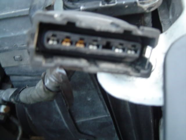
Test the VC pin (pin 4, between the blank spot and the brass contact) on the connector for a short to ground. Then test the continuity of the line between that point and the VC pin on the ECU's harness (look at the pinout diagram in the MAFT Pro writeup for the location). If that's good test the continuity between those two spots and the IDL contact on the TPS (it's pin 1, blue wire with a red stripe). If all of that checks out plug everything back together, turn the ignition to the start position (don't start the car) and test the voltage between ground and VC. Should be between .1v and 1v, IIRC.
http://www.cygnusx1.net/Supra/Library/TEWD/MK3/manual.aspx?Section=Main&Page=57
http://www.cygnusx1.net/Supra/Library/TSRM/MK3/manual.aspx?Section=FI&Page=94
EDIT: So, what did that new AFM set you back anyway? If you don't mind my asking.
EDIT2: Also test for 12v at the E2 pin on both the AFM and TPS harnesses with the key turned on, but the car not started.
Last edited:
Will my Digital Multimeter even work for testing this? I don't know what the hell to do to test this... Like where do i put the Positive terminal and Negative? and what do i set the multimeter to?
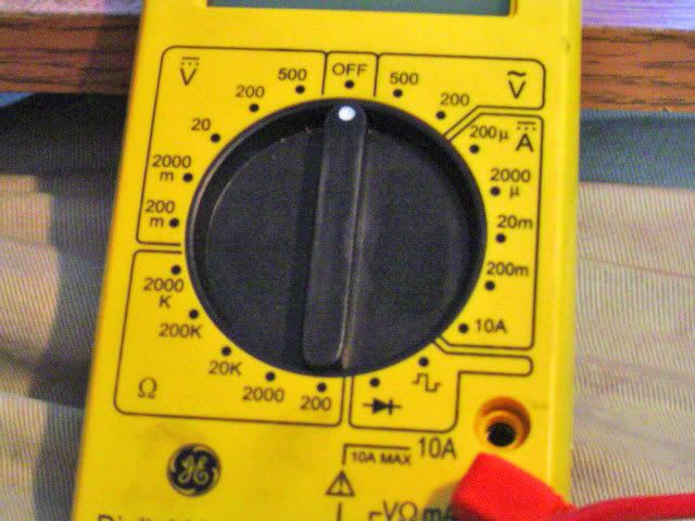
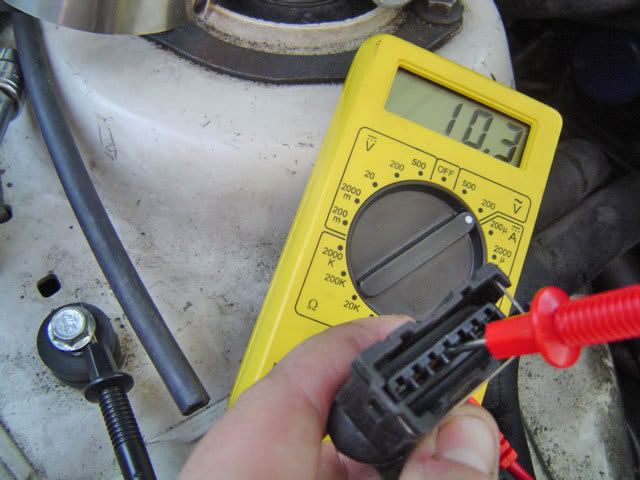
I DON'T KNOW IF I'M DOING THIS RIGHT...?!?
I DON'T KNOW IF I'M DOING THIS RIGHT...?!?
Last edited:
Hey Chris, sorry, I'm at work and don't have much time to help today.
Here's a video tutorial for you.
http://tangentsoft.net/elec/movies/tt06.html
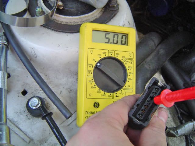
I can't tell if that DMM has a continuity function, check the manual. If not, you can test continuity with the 200Ω resistance function. The resistance shouldn't be more than just a few Ohms (Ω. If the results are infinite, it means there's a complete break. If the resistance is high there may be a break, a poor connection or heavy oxidization.
You may need to use a piece of good wire to extend your test leads. You place one lead on the AFM harness side the other on the ECU harness side. Then you'll test across the harness from the TPS harness connector to the ECU harness connector.
Then you test the E2 voltage like you're doing in those pictures except that E2 is one pin over from the one you've got pictured. You're testing DC so when you're testing voltages you want the range with the dotted "=" sign, not the range with the "~". For testing resistance it's the "Ω" range.
Here's a video tutorial for you.
http://tangentsoft.net/elec/movies/tt06.html
I can't tell if that DMM has a continuity function, check the manual. If not, you can test continuity with the 200Ω resistance function. The resistance shouldn't be more than just a few Ohms (Ω
. If the results are infinite, it means there's a complete break. If the resistance is high there may be a break, a poor connection or heavy oxidization.You may need to use a piece of good wire to extend your test leads. You place one lead on the AFM harness side the other on the ECU harness side. Then you'll test across the harness from the TPS harness connector to the ECU harness connector.
Then you test the E2 voltage like you're doing in those pictures except that E2 is one pin over from the one you've got pictured. You're testing DC so when you're testing voltages you want the range with the dotted "=" sign, not the range with the "~". For testing resistance it's the "Ω" range.
Hey I just realized I made a mistake in my posts. E2 is a ground. You don't need to test it for 12v. Just test that run of wire the same as the VC wire.
Just a note: VC is 5 vdc and can be referenced to E2. VS can be tested from either end using a long wire or with either end shorted to ground. It's better to test voltage levels than resistance because that's what the ECU samples. Seeing how a vane meter is pretty simple though I suppose resistance will do.
No problem. Since conventional EFI uses 12 volts as the reference it's understandable. I've been watching and you're doing a hell of a job on these minor electrical threads. Thanks, saves me from doing it. It's also obvious you've more patience
Now i'm getting code 24 and 31!?! (air intake temp sensor) all these codes are afm related but i have a brand new afm...
refer to ecu pinouts and the wiring diagram for the afm circuit. set your multimeter to 200 ohms, place one lead of the meter at the afm connector in the engine bay, the other lead at the ecu connector inside the car. you may need a safety pin to probe the terminals because the leads probably won't fit.
you should get around 0.1-0.3 ohms. personally, anything over 0.5 ohm I'd start replacing the wire.
you should get around 0.1-0.3 ohms. personally, anything over 0.5 ohm I'd start replacing the wire.