First let me say this, what you see below is a half finished project. I had originally planned to include wiring for both MKIV/Aristo 2JZ-GTE's in to both the pre and post 89 chassis. But I never reached a point where I felt comfortable with the way the info was edited and presented. I wanted something that was easy to read and understand by someone with a little electrical knowledge. After several failed attempts I shelved the project till later. What you see below is essentially scraps put together from one of my better attempts. It could be better but if I don't put it out here now, it may never be. What follows is the culmination of countless hours picking through the info on arnout's site supras.nl, much time in between the pages of an 89TSRM, a 87 Supra EWD, 95 TSRM, and a 93 GS300 EWD.
I would also like to state that this information is presented here for research purposes. My recommendation, for a well built fully functioning swap harness is to contact drtweak and get one from him.
________________________________________________________________________
This is for swapping a 1st gen Aristo 2JZ-GTE into a pre89 MKIII
How to read: The first part deals with the connectors that are present and their associated pinouts. So you know what they do and can decide if you want to keep them. For example pin 6 thru 8 on Connector 'C' deals with the traction control and can be deleted.
The second section titled 'Connections' deals with the the hybrid connections that need to be made between the 2JZ harness and the MKIII harness. Three connectors from the 7M main engine harness are required to be spliced in to the 2JZ harness.
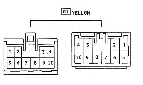
M1
Pin # 1 – Reverse Light Power from Switch ((R-B) Also power for A/T indicator/neutral start switch)
Pin # 2 –Reverse Light power to Switch(Y)
Pin # 3- Speed sensor from combo meter. (ECU/P <->Body/Y-R)
Pin # 4 –Tach Signal (B)
Pin # 5 –Turbo Indicator light(Outside U.S.)
Pin # 6 –Ground(MASS) for Combo Meter (BR)
Pin # 7 –Oil Pressure Signal for Combo Meter (Y-B)
Pin # 8 –Check Engine Light ”W” (GR-G)
Pin # 9 –Water Temp Signal for Combo Meter (Y-G)
Pin # 10 –Defogger Relay (V)
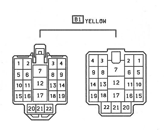
B1
Pin # 1
Pin # 2 - *A/T Only* ‘L3’ Signal from ECT ECU to TCCS (R-W)
Pin # 3 -* A/T Only* ‘L2’ Signal from ECT ECU to TCCS(R)
Pin # 4 -* A/T Only* ‘L1’ Signal from ECT ECU to TCCS(B)
Pin # 5 – ‘E2’ Signal on Diag Block(B-R) used to monitor fuel pump voltages
Pin # 6 – Ground to activate Fuel pump relay (G) Normally the ECU grounds, Ground to MASS for swap
Pin # 7 – *A/T only *Power for secondary coil in circuit opening relay(B-L)
Pin # 8 – Fuel pressure down. If this wire is grounded, voltage to the fuel pump is reduced (Y)
Pin # 9 – Power to Circuit opening relay for Fuel pump (B-R)
Pin # 10
Pin # 11 -*A/T Only*Neutral signal for ECT ECU (W)
Pin # 12 – “Start” signal from relay to starter (Engine/B-L <->Body/B-W)
Pin # 13 – Signal from A/C amplifier (L-R)
Pin # 14 –From Diag Block to test for TEMS Hard mode (V)
Pin # 15 –Cruise Control Clutch Switch (B-Y)
Pin # 16 –IG switch power to ECU(B-O)
Pin # 17 –Power from Ignition switch IG2 (B-O)
Pin # 18- Signal from theft computer to theft deterrent horn (Y-L)
Pin # 19 –From Headlight relay(R-Y)
Pin# 20 –injector signal to Super Monitor (W-L)
Pin # 21 – ‘T’ Signal to Super Monitor(R-G)
Pin # 22 – From Super Monitor computer to ground(MASS) (BR)
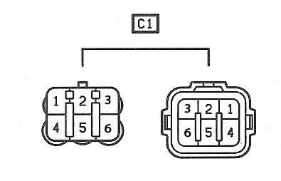
C1
Pin # 1 - Batt signal from 15A EFI fuse (B-Y)This source is taken before the EFI main Relay
Pin # 2 - M-Rel coil signal from ECU (B-O) This is the signal that the ECU sends to activate the EFI Relay
Pin # 3 –Source from 15A HAZ-HORN Fuse to Theft Deterrent horn (W)
Pin # 4 – Batt+ from EFI main relay (via 15A EFI) (B-R)This source taken after the EFI relay
Pin # 5 –GND signal from the EFI relay coil.(W-B) This signal goes to the Diag Block ‘E2’
Pin # 6
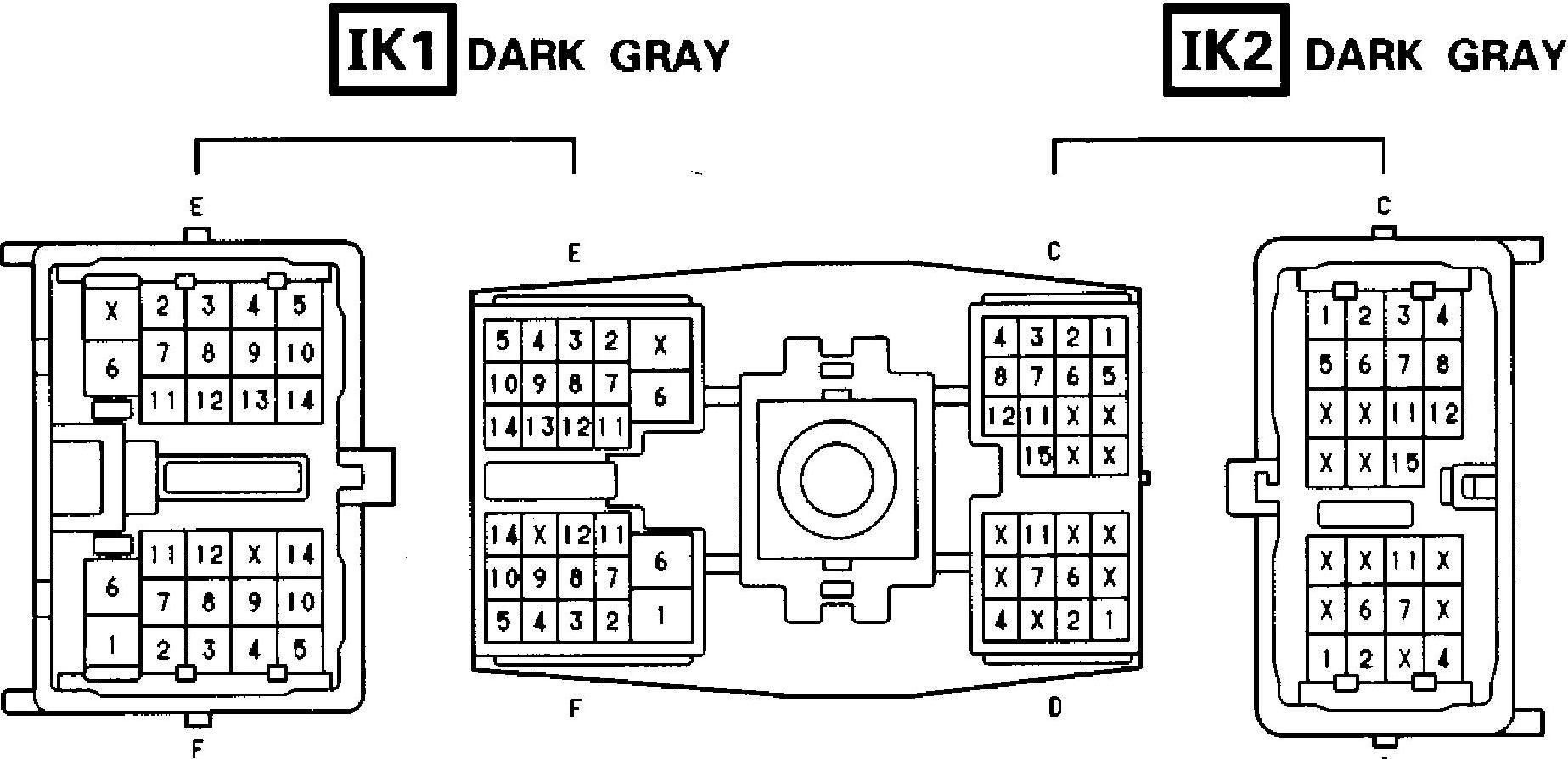
Connector C
Pin # 1 –Aircon lock in signal (GR-R)
Pin # 2 –Aircon SG for Lock in (GR)
Pin # 3 –Throttle Actuator for Trac System (W)
Pin # 4 –Throttle Actuator for Trac System (R)
Pin # 5 –Aircon Clutch signal (B-W)
Pin # 6 –Throttle actuator for Trac System (B)
Pin # 7- Throttle actuator for Trac System (G)
Pin # 8 –Throttle actuator for Trac System (Y)
Pin # 9
Pin # 10
Pin # 11 –Throttle Actuator for Trac System (L)
Pin # 12 –Throttle actuator for Trac System (GR shield)
Pin # 13 –Oil Valve for Hydro Fan (L-Y)
Pin # 14
Pin # 15 –FP signal for Check Box
Pin # 16
Pin # 17
Connector D
Pin # 1 –Oil level light (Y-R)
Pin # 2 –A/T control pin 8 (R-L)
Pin # 3
Pin # 4 –AB Check Signal (B-Y)
Pin # 5 –TEM Check Signal (GR-R)
Pin # 6
Pin # 7 –WA Check Signal (P)
Pin # 8 –CCO Check Signal (GR-B)
Pin # 9 –Oil Valve for radiator fan(pressure driven)(B)
Pin # 10 –OP1 check signal (P-L)
Pin # 11 –WB Check Signal (P)
Pin # 12
Connector E
Pin # 1
Pin # 2 –‘W’ (warning) Check Engine Signal (diagnostics box)(B-Y)
Pin # 3 - +12Volt for electronic controlled transmission (B-R)
Pin # 4 -A/T neutral start (pin 6 on tranny)(B-Y)
Pin # 5 –A/T neutral start (pin 5 on tranny) (B-W)
Pin # 6 –Tc Check Signal (Diag Box) (Y-B)
Pin # 7 –TE2 Check Signal (Diag Box) (L-B)
Pin # 8 –“N” Signal from A/T indication switch for dash (G-R)
Pin # 9 –“2” Signal from A/T indication switch for dash (G-O)
Pin # 10 –“L” Signal from A/T indication switch for dash (G-B)
Pin # 11 –“D” Signal from A/T indicator switch for dash (G-W)
Pin # 12 –“P” Signal from A/T indicator switch for dash (G-Y)
Pin # 13 –“R” Signal from A/T indicator switch for dash (R-B)
Pin # 14 - +12Volt for A/T indication switch and backup lights
Connector F
Pin # 1 –Signal for Starter (B)(FAT)
Pin # 2 –SPD signal from speed sensor (pin 3)(L-R)*Delete if Auto Removed*
Pin # 3 –SPD signal from speed sensor (pin 2)(L-Y) *Delete if Auto Removed*
Pin # 4 –TE1 Check Signal (Diag Box)(L-W)
Pin # 5 –TS Check Signal (Diag Box) (G)
Pin # 6 -+12Volt for igniter ect. (B-O)
Pin # 7 –Ground (BR)
Pin # 8 - Signal for Oil Pressure Gauge (Y-B)
Pin # 9- Signal for Water Temp gauge on Combo Meter(Y-G)
Pin # 10 - VF1 Check Signal(Diag Box)(G-R)
Pin # 11 – Ground (BR)
Pin # 12 –RPM Signal (B)
Pin # 13
Pin # 14
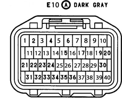
E10
Pin # 1 –‘IGSW’ Ignition Switch signal from IG2 (B-O)
Pin # 2 –‘SPD’ Speed signal (V)
Pin # 3 -
Pin # 4 –‘STP’ Signal from stop light switch(G-W)
Pin # 5
Pin # 6 –‘W’ Warning lamp indicator (B-Y)*CEL light*
Pin # 7
Pin # 8 –‘R’ Indicator Light(R-B)
Pin # 9 –‘2’Indicator Light(G-O)
Pin # 10 –‘L’ Indicator Light(G-B)
Pin # 11
Pin # 12 –‘OD1’ From Cruise control ECU(V)*ECT signal*
Pin # 13
Pin # 14
Pin # 15 –‘ELS’ Idle-up signal from defogger relay(LG-B)
Pin # 16
Pin # 17 –‘TT’ Signal for Data Link connector 2(LG)
Pin # 18 –‘P’ECT Pattern select switch
Pin # 19 –‘TE2’ Signal for check connector(L-B)
Pin # 20 –‘TE1’ Signal for check connector(L-O)
Pin # 21 –‘DI’ Control Signal from Fuel Pump Computer(LG-R)
Pin # 22 –‘FPC’ Control Signal to Fuel Pump Computer(G-R)
Pin # 23 –‘ACMG’Signal From magnetic clutch relay(W)
Pin # 24 –‘M-REL’ Signal to activate the main EFI Relay (G-O)
Pin # 25
Pin # 26
Pin # 27
Pin # 28 –‘OD2’ From O/D select Main Switch(B-R) *ECT signal*
Pin # 29
Pin # 30
Pin # 31 –‘+B’ 12volt signal taken post-EFI Relay(B-R)
Pin # 32 -–‘+B1’ 12volt signal taken post-EFI Relay(B-R)*spliced into same line as ‘+B’ pin 31*
Pin # 33 –‘BATT’ constant 12Volt signal taken pre-EFI Relay(W-L)
Pin # 34 –‘A/C’ From A/C Lock amplifier(B)
Pin # 35 –‘PS’ Signal for power steering pressure switch(G-Y)
Pin # 36
Pin # 37 –‘TR’ From Trac Control Computer (P)
Pin # 38 –‘NEO’ From Trac Control Computer (BR-W)
Pin # 39 –‘VT02’ From Trac Control Computer(Y-R)
Pin # 40 –‘VT01’ From Trac Control Computer(P-L)
Connections
M1
Pin #1 - This branch should be transplanted from the 7M harness. Line from (M1 pin 1) to (B pin 1) should be preserved *see appendix for connector ‘B’
Pin #2 – This branch should be transplanted from the 7M harness. Line from (M1 pin 2) to (B pin 2) should be preserved *see appendix for connector ‘B’
Pin #3 –‘SPD’ -> E10 pin 2
Pin #4 –‘Tach’ -> IK1-F pin 12
Pin #6 –‘MASS’  MASS(Ground)
Pin #7 –‘Oil Pressure’ ->IK1-F pin 8
Pin #8 –‘W’ -> E10 pin 6, IK1-E pin 2
Pin #9 –‘WATER TEMP’ -> IK1-F pin 9
Pin #10 –‘Defog relay’ -> E10 pin 15
B1
Pin #5 –‘FP Voltage’ ->IK2-C pin 15
Pin #6 –‘FP Relay Ground’ -> MASS(Ground) *see Appendix
Pin #9 –‘12V for COR’ ->C1 pin 4
Pin #12 –‘Start’ -> IK1-F pin 1
Pin #13 –‘A/C Amplifier’ E10 Pin 34
Pin #15 –‘Cruise Clutch’ ->E9 pin 76 *see Appendix
Pin #16 –‘IGSW’ ->E10 pin 1
Pin #17 –‘IG2’ -> IK1-F pin 6,
C1
Pin #1 –‘Batt’ ->E10 pin 33
Pin #2 –‘M-REL’ -> E10 pin 24
Pin #4 – ‘+B’ -> E10 pin 31,32
Appendix
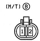
Connector ‘B’ is located at the R154 transmission and is used for the reverse light switch,
and is transplanted for this swap.
Fuel Pump Relay
To activate the relay the 7M TCCS normally grounds pin 6 of connector B1 when the ECU see an RPM signal. This is a safety feature so the fuel pump will stop if the engine stops, if something like an accident were to happen. The 2JZ ECU does not do this and has a separate computer to accomplish this task. At the moment I’m not sure how to swap that computer over. So unfortunately the simplest solution is to physically ground the wire from B1 pin 6. This allows the fuel pump relay to kick on whenever the ignition switch is turned on. However this disables the rpm triggered safety feature. Hopefully I’ll come up with a better solution in the near future.
E9 Connector
Due to the limited pins that have to be messed with on this connector I decided to leave the pin out off the main pin out. Simply reference the pin numbers from above.
Acronyms
FP – Fuel Pump
COR – Circuit Opening Relay
TCCS – Toyota Computer Controlled System i.e the ECU
SPD – Speed
IG - Ignition
MASS-Chassis Ground
*All connections shown in red are the bare minimum necessary to start the engine. Just to test if the motor functions.
I would also like to state that this information is presented here for research purposes. My recommendation, for a well built fully functioning swap harness is to contact drtweak and get one from him.
________________________________________________________________________
This is for swapping a 1st gen Aristo 2JZ-GTE into a pre89 MKIII
How to read: The first part deals with the connectors that are present and their associated pinouts. So you know what they do and can decide if you want to keep them. For example pin 6 thru 8 on Connector 'C' deals with the traction control and can be deleted.
The second section titled 'Connections' deals with the the hybrid connections that need to be made between the 2JZ harness and the MKIII harness. Three connectors from the 7M main engine harness are required to be spliced in to the 2JZ harness.
M1
Pin # 1 – Reverse Light Power from Switch ((R-B) Also power for A/T indicator/neutral start switch)
Pin # 2 –Reverse Light power to Switch(Y)
Pin # 3- Speed sensor from combo meter. (ECU/P <->Body/Y-R)
Pin # 4 –Tach Signal (B)
Pin # 5 –Turbo Indicator light(Outside U.S.)
Pin # 6 –Ground(MASS) for Combo Meter (BR)
Pin # 7 –Oil Pressure Signal for Combo Meter (Y-B)
Pin # 8 –Check Engine Light ”W” (GR-G)
Pin # 9 –Water Temp Signal for Combo Meter (Y-G)
Pin # 10 –Defogger Relay (V)
B1
Pin # 1
Pin # 2 - *A/T Only* ‘L3’ Signal from ECT ECU to TCCS (R-W)
Pin # 3 -* A/T Only* ‘L2’ Signal from ECT ECU to TCCS(R)
Pin # 4 -* A/T Only* ‘L1’ Signal from ECT ECU to TCCS(B)
Pin # 5 – ‘E2’ Signal on Diag Block(B-R) used to monitor fuel pump voltages
Pin # 6 – Ground to activate Fuel pump relay (G) Normally the ECU grounds, Ground to MASS for swap
Pin # 7 – *A/T only *Power for secondary coil in circuit opening relay(B-L)
Pin # 8 – Fuel pressure down. If this wire is grounded, voltage to the fuel pump is reduced (Y)
Pin # 9 – Power to Circuit opening relay for Fuel pump (B-R)
Pin # 10
Pin # 11 -*A/T Only*Neutral signal for ECT ECU (W)
Pin # 12 – “Start” signal from relay to starter (Engine/B-L <->Body/B-W)
Pin # 13 – Signal from A/C amplifier (L-R)
Pin # 14 –From Diag Block to test for TEMS Hard mode (V)
Pin # 15 –Cruise Control Clutch Switch (B-Y)
Pin # 16 –IG switch power to ECU(B-O)
Pin # 17 –Power from Ignition switch IG2 (B-O)
Pin # 18- Signal from theft computer to theft deterrent horn (Y-L)
Pin # 19 –From Headlight relay(R-Y)
Pin# 20 –injector signal to Super Monitor (W-L)
Pin # 21 – ‘T’ Signal to Super Monitor(R-G)
Pin # 22 – From Super Monitor computer to ground(MASS) (BR)
C1
Pin # 1 - Batt signal from 15A EFI fuse (B-Y)This source is taken before the EFI main Relay
Pin # 2 - M-Rel coil signal from ECU (B-O) This is the signal that the ECU sends to activate the EFI Relay
Pin # 3 –Source from 15A HAZ-HORN Fuse to Theft Deterrent horn (W)
Pin # 4 – Batt+ from EFI main relay (via 15A EFI) (B-R)This source taken after the EFI relay
Pin # 5 –GND signal from the EFI relay coil.(W-B) This signal goes to the Diag Block ‘E2’
Pin # 6
Connector C
Pin # 1 –Aircon lock in signal (GR-R)
Pin # 2 –Aircon SG for Lock in (GR)
Pin # 3 –Throttle Actuator for Trac System (W)
Pin # 4 –Throttle Actuator for Trac System (R)
Pin # 5 –Aircon Clutch signal (B-W)
Pin # 6 –Throttle actuator for Trac System (B)
Pin # 7- Throttle actuator for Trac System (G)
Pin # 8 –Throttle actuator for Trac System (Y)
Pin # 9
Pin # 10
Pin # 11 –Throttle Actuator for Trac System (L)
Pin # 12 –Throttle actuator for Trac System (GR shield)
Pin # 13 –Oil Valve for Hydro Fan (L-Y)
Pin # 14
Pin # 15 –FP signal for Check Box
Pin # 16
Pin # 17
Connector D
Pin # 1 –Oil level light (Y-R)
Pin # 2 –A/T control pin 8 (R-L)
Pin # 3
Pin # 4 –AB Check Signal (B-Y)
Pin # 5 –TEM Check Signal (GR-R)
Pin # 6
Pin # 7 –WA Check Signal (P)
Pin # 8 –CCO Check Signal (GR-B)
Pin # 9 –Oil Valve for radiator fan(pressure driven)(B)
Pin # 10 –OP1 check signal (P-L)
Pin # 11 –WB Check Signal (P)
Pin # 12
Connector E
Pin # 1
Pin # 2 –‘W’ (warning) Check Engine Signal (diagnostics box)(B-Y)
Pin # 3 - +12Volt for electronic controlled transmission (B-R)
Pin # 4 -A/T neutral start (pin 6 on tranny)(B-Y)
Pin # 5 –A/T neutral start (pin 5 on tranny) (B-W)
Pin # 6 –Tc Check Signal (Diag Box) (Y-B)
Pin # 7 –TE2 Check Signal (Diag Box) (L-B)
Pin # 8 –“N” Signal from A/T indication switch for dash (G-R)
Pin # 9 –“2” Signal from A/T indication switch for dash (G-O)
Pin # 10 –“L” Signal from A/T indication switch for dash (G-B)
Pin # 11 –“D” Signal from A/T indicator switch for dash (G-W)
Pin # 12 –“P” Signal from A/T indicator switch for dash (G-Y)
Pin # 13 –“R” Signal from A/T indicator switch for dash (R-B)
Pin # 14 - +12Volt for A/T indication switch and backup lights
Connector F
Pin # 1 –Signal for Starter (B)(FAT)
Pin # 2 –SPD signal from speed sensor (pin 3)(L-R)*Delete if Auto Removed*
Pin # 3 –SPD signal from speed sensor (pin 2)(L-Y) *Delete if Auto Removed*
Pin # 4 –TE1 Check Signal (Diag Box)(L-W)
Pin # 5 –TS Check Signal (Diag Box) (G)
Pin # 6 -+12Volt for igniter ect. (B-O)
Pin # 7 –Ground (BR)
Pin # 8 - Signal for Oil Pressure Gauge (Y-B)
Pin # 9- Signal for Water Temp gauge on Combo Meter(Y-G)
Pin # 10 - VF1 Check Signal(Diag Box)(G-R)
Pin # 11 – Ground (BR)
Pin # 12 –RPM Signal (B)
Pin # 13
Pin # 14
E10
Pin # 1 –‘IGSW’ Ignition Switch signal from IG2 (B-O)
Pin # 2 –‘SPD’ Speed signal (V)
Pin # 3 -
Pin # 4 –‘STP’ Signal from stop light switch(G-W)
Pin # 5
Pin # 6 –‘W’ Warning lamp indicator (B-Y)*CEL light*
Pin # 7
Pin # 8 –‘R’ Indicator Light(R-B)
Pin # 9 –‘2’Indicator Light(G-O)
Pin # 10 –‘L’ Indicator Light(G-B)
Pin # 11
Pin # 12 –‘OD1’ From Cruise control ECU(V)*ECT signal*
Pin # 13
Pin # 14
Pin # 15 –‘ELS’ Idle-up signal from defogger relay(LG-B)
Pin # 16
Pin # 17 –‘TT’ Signal for Data Link connector 2(LG)
Pin # 18 –‘P’ECT Pattern select switch
Pin # 19 –‘TE2’ Signal for check connector(L-B)
Pin # 20 –‘TE1’ Signal for check connector(L-O)
Pin # 21 –‘DI’ Control Signal from Fuel Pump Computer(LG-R)
Pin # 22 –‘FPC’ Control Signal to Fuel Pump Computer(G-R)
Pin # 23 –‘ACMG’Signal From magnetic clutch relay(W)
Pin # 24 –‘M-REL’ Signal to activate the main EFI Relay (G-O)
Pin # 25
Pin # 26
Pin # 27
Pin # 28 –‘OD2’ From O/D select Main Switch(B-R) *ECT signal*
Pin # 29
Pin # 30
Pin # 31 –‘+B’ 12volt signal taken post-EFI Relay(B-R)
Pin # 32 -–‘+B1’ 12volt signal taken post-EFI Relay(B-R)*spliced into same line as ‘+B’ pin 31*
Pin # 33 –‘BATT’ constant 12Volt signal taken pre-EFI Relay(W-L)
Pin # 34 –‘A/C’ From A/C Lock amplifier(B)
Pin # 35 –‘PS’ Signal for power steering pressure switch(G-Y)
Pin # 36
Pin # 37 –‘TR’ From Trac Control Computer (P)
Pin # 38 –‘NEO’ From Trac Control Computer (BR-W)
Pin # 39 –‘VT02’ From Trac Control Computer(Y-R)
Pin # 40 –‘VT01’ From Trac Control Computer(P-L)
Connections
M1
Pin #1 - This branch should be transplanted from the 7M harness. Line from (M1 pin 1) to (B pin 1) should be preserved *see appendix for connector ‘B’
Pin #2 – This branch should be transplanted from the 7M harness. Line from (M1 pin 2) to (B pin 2) should be preserved *see appendix for connector ‘B’
Pin #3 –‘SPD’ -> E10 pin 2
Pin #4 –‘Tach’ -> IK1-F pin 12
Pin #6 –‘MASS’  MASS(Ground)
Pin #7 –‘Oil Pressure’ ->IK1-F pin 8
Pin #8 –‘W’ -> E10 pin 6, IK1-E pin 2
Pin #9 –‘WATER TEMP’ -> IK1-F pin 9
Pin #10 –‘Defog relay’ -> E10 pin 15
B1
Pin #5 –‘FP Voltage’ ->IK2-C pin 15
Pin #6 –‘FP Relay Ground’ -> MASS(Ground) *see Appendix
Pin #9 –‘12V for COR’ ->C1 pin 4
Pin #12 –‘Start’ -> IK1-F pin 1
Pin #13 –‘A/C Amplifier’ E10 Pin 34
Pin #15 –‘Cruise Clutch’ ->E9 pin 76 *see Appendix
Pin #16 –‘IGSW’ ->E10 pin 1
Pin #17 –‘IG2’ -> IK1-F pin 6,
C1
Pin #1 –‘Batt’ ->E10 pin 33
Pin #2 –‘M-REL’ -> E10 pin 24
Pin #4 – ‘+B’ -> E10 pin 31,32
Appendix
Connector ‘B’ is located at the R154 transmission and is used for the reverse light switch,
and is transplanted for this swap.
Fuel Pump Relay
To activate the relay the 7M TCCS normally grounds pin 6 of connector B1 when the ECU see an RPM signal. This is a safety feature so the fuel pump will stop if the engine stops, if something like an accident were to happen. The 2JZ ECU does not do this and has a separate computer to accomplish this task. At the moment I’m not sure how to swap that computer over. So unfortunately the simplest solution is to physically ground the wire from B1 pin 6. This allows the fuel pump relay to kick on whenever the ignition switch is turned on. However this disables the rpm triggered safety feature. Hopefully I’ll come up with a better solution in the near future.
E9 Connector
Due to the limited pins that have to be messed with on this connector I decided to leave the pin out off the main pin out. Simply reference the pin numbers from above.
Acronyms
FP – Fuel Pump
COR – Circuit Opening Relay
TCCS – Toyota Computer Controlled System i.e the ECU
SPD – Speed
IG - Ignition
MASS-Chassis Ground
*All connections shown in red are the bare minimum necessary to start the engine. Just to test if the motor functions.
Last edited:

")