
Hi all, I thought I would put together a complete “guide” if you will for a Pre-89 1UZ-FE swapped Supra. This swap is gaining in popularity so I figured if we have a good platform to get wiring information it would help ease the process. First I will list the Supra connectors, then a short description, and pin layout. Then I will list the 1UZ-FE connectors, then a short description, and pin layout. Finally I will give a “guide” to connecting the two to make a running vehicle. This "guide" will be dynamic until otherwise said, so I will be updating this periodically as I gain information.
I used a EWD Book for a 1986.5 Supra (NA Only), and a EWD book for a 1994 SC (300 & 400), and 1997 SC (300 & 400). 1994-1997 SC3/400 from my understanding were transition years in wiring much like our Pre-89 to 89 to Post-89 Supra wiring. So I have started with a 1994 EWD, I just recently picked up a 1997 EWD, and I plan to get a 1996 soon. In my 87 I have a post 1996 (A transition year for the 1UZ) and I noticed a few extra wires on plug IJ1 that needed power but the 1994 book worked just fine.
Since there is so much information I will attempt to post in separate replies, Thanks for looking.
---------- Post added at 10:54 PM ---------- Previous post was at 10:52 PM ----------
Pre-89 NA Toyota Supra:
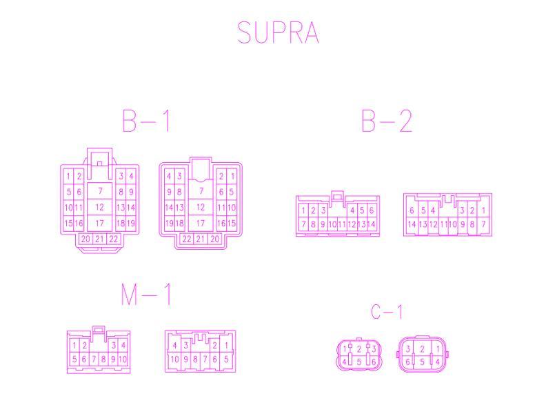
Interior:
- B-1 – 22 Pins, Yellow in color
o Pin 1 – Black-Yellow in color
§ From “Water VSV” to “Air Mix Control”
o Pin 2 – Red-White in color
§ From “ECT ECU” to “ECU”
o Pin 3 – Red in color
§ From “ECT ECU” to “ECU”
o Pin 4 – Black in color
§ From “ECT ECU” to “ECU”
o Pin 5 – Black-Red in color
§ From “Fuel Pump” to “Check Connector”
o Pin 6 – Green in color
§ From “Circuit Open Relay” to “Air Flow Meter”
o Pin 7 – Black-Light Blue in color
§ From “Circuit Open Relay” to “ECU” and “Starter” (A/T Only)
o Pin 8 – Yellow in color
§ From “ECU” to “Fuel Pump Control Relay”
o Pin 9 – Black-Red in color
§ From “EFI Main Relay” to “Circuit Open Relay”
o Pin 10 – Empty
§ No pin
o Pin 11 – White in color
§ From “A/T Indicator S/W” to “ECT ECU”
o Pin 12 – Black-White in color
§ From “Starter Relay” to “Starter”
o Pin 13 – Light Blue in color
§ From “AC Amplifier” to “ECU”
o Pin 14 – Violet in color
§ From “TEMS ECU” to “Check Connector”
o Pin 15 – Black-Yellow in color
§ From “Cruise Control Clutch S/W” to “ECU”
o Pin 16 – Black-Orange in color
§ From “7.5A IGN Fuse” to “ECU”
o Pin 17 – Black-Orange in color
§ From “Ignition S/W” to “Igniter” and “EFI Resistor”
o Pin 18 – Yellow in color
§ From “Theft Horn” to “Integration Relay No.2”
o Pin 19 – Red-Yellow in color
§ From “Headlight Relay” to “ECU”
o Pin 20 – White-Light Blue in color
§ From “Super Monitor” to “ECU”
o Pin 21 – Red-Green in color
§ From “Super Monitor” to “ECU”
o Pin 22 – Brown in color
§ From “Super Monitor” to “Ground” on Intake Manifold
- B-2 – 14 Pins, White in color
o Pin 1 – Green in color
§ From “A/T” Indicator S/W” to “ECT ECU”
o Pin 2 – Red-Green in color
§ From “ECT Solenoid” to “ECT ECU”
o Pin 3 – Green-Yellow in color
§ From “ECT Solenoid” to “ECT ECU”
o Pin 4 – Yellow in color
§ Dead Ends From Engine Harness to B-2
o Pin 5 – Black in color
§ Dead Ends From Engine Harness to B-2
o Pin 6 – Red in color
§ From “Cruise Control Computer” to “ECT ECU” and “ECU”
o Pin 7 – Light Blue in color
§ From “A/T Indicator S/W” to “ECT ECU”
o Pin 8 – Green-Black in color
§ From “ECT Solenoid” to “ECT ECU”
o Pin 9 – Red-Light Blue in color
§ From “ECT Solenoid” to “ECT ECU”
o Pin 10 – Red in color
§ Dead End
o Pin 11 – Blue-Yellow in color
§ Dead End
o Pin 12 – Red-Black in color
§ Dead End
o Pin 13 – Yellow-Blue in color
§ From “ECT ECU” to “Comb. Meter (SPD Sensor)”
o Pin 14 – Yellow-Black in color
§ From “Check Connector” to “ECT ECU”
- M-1 – 10 Pins, Yellow in color
o Pin 1 – Red-Black in color
§ From “Back Up S/W to “Back Up Lights”
o Pin 2 – Yellow in color
§ From “7.5A Gauge Fuse” to “Back Up Lights”
o Pin 3 – Pink in color (Engine Harness Side)
§ From “ECU” to “Comb. Meter (SPD Sensor)”
o Pin 4 – Black in color
§ From “Igniter” to “Super Monitor”, “ECU”, and “Comb. Meter” (Tach signal)
o Pin 5 – Empty
§ No Pin
o Pin 6 – Brown in color
§ From “Comb. Meter” to “Ground (Intake Manifold)”
o Pin 7 – Yellow-Black in color
§ From “Oil Pressure Sending Unit” to “Comb. Meter”
o Pin 8 – Gray-Green in color
§ From “ECU” to “CEL (Check Engine Light)”
o Pin 9 – Yellow-Green in color
§ From “Water Temp Sensor” to “Comb. Meter”
o Pin 10 – Violet in color
§ From “Defogger Relay” to “ECU”
Engine Bay:
- C-1 – 6 Pins, Yellow in color
o Pin 1 – Black-Yellow in color
§ From “15A EFI Fuse” to “ECU”
o Pin 2 – Black-Orange in color
§ From “ECU” to “EFI Main Relay”
o Pin 3 – White in color
§ From “15A Haz-Horn Fuse” to “Theft Horn”
o Pin 4 – Black-Red in color
§ From “EFI Main Relay” to “ECU”
o Pin 5 – White-Black in color
§ From “AFM” to “Ground (Left Fender)”
o Pin6 – Empty
§ No Pin
---------- Post added at 10:56 PM ---------- Previous post was at 10:54 PM ----------
1994 Lexus SC400:
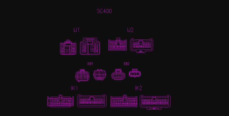
Interior:
- IJ1 – 14 Pins, Gray in color
o Pin 1 – Green in color
§ From “FPECU” to “Check Connector”
o Pin 2 – Red-Blue in color
§ From “10A HTR Fuse” to “Water VSV”
o Pin 3 – Empty
§ No Pin? Confirm?
o Pin 4 – White in color
§ From “25A Haz-Horn Fuse” to “Haz Horn”
o Pin 5 – Empty
§ No Pin? Confirm?
o Pin 6 – Black-White in color
§ From “IGN S/W” to “Neutral Safety S/W”
o Pin 7 – Empty
§ No Pin? Confirm?
o Pin 8 – Pink in color
§ From “ECU” to “FPECU”
o Pin 9 – Black-Orange in color
§ From “Haz-Horn” to “Theft ECU”
o Pin 10 – Yellow in color
§ From “10A Gauge Fuse” to “Back Up S/W”
o Pin 11 – Empty
§ No Pin? Confirm?
o Pin 12 – Black-Red in color
§ From “EFI Main Relay” to “FPECU” and “Sub o2 Sensors”
o Pin 13 – White-Black in color
§ From “Trac ECU” to “Ground”
o Pin 14 – Red-Green in color
§ From “ECU” to “FPECU”
- IJ2 – 17 Pins, Gray in color
o Pin 1 – Red in color
§ From “Cruise CTRL ECU” to “ECU”
o Pin 2 – White-Red in color
§ From “Cruise CTRL ECU” to “ECU”
o Pin 3 – Pink in color
§ From “Comb. Meter” to “ECU”
o Pin 4 – Green-Blue in color
§ From “Cruise CTRL ECU” to “ECU”
o Pin 5 – Empty
§ No Pin? Confirm?
o Pin 6 – Light Green-Black in color
§ From “Progressive Power Steering ECU” to “PPS Solenoid”
o Pin 7 – Green-White in color
§ From “Stop Light S/W” to “ECU”
o Pin 8 – Empty
§ No Pin? Confirm?
o Pin 9 – Brown-Yellow in color
§ From Cruise “CTRL ECU” to “ECU”
o Pin 10 – Empty
§ No Pin? Confirm?
o Pin 11 – Black-Orange in color
§ From “7.5A IGN Fuse” to “ECU”
o Pin 12 – Black-Red in color
§ From “15A ECU-IG Fuse” to “Trac ECU”
o Pin 13 – Empty
§ No Pin? Confirm?
o Pin 14 – Empty
§ No Pin? Confirm?
o Pin 15 – Empty
§ No Pin? Confirm?
o Pin 16 – Light Green-Red in color
§ From “PPS Solenoid” to “PPS ECU”
o Pin 17 – Blue in color
§ From “ECU” to “Kick Down S/W”
- IK1 – 23 Pin, Orange in color
o Pin 1 – Brown in color
§ From “Left o2 Sub” to “Ground”
o Pin 2 – Green – Yellow in color
§ From “ECU” to “Data Link Connector 2 (TDCL)”
o Pin 3 – Gray-Yellow in color
§ From “ECU” to “TDCL”
o Pin 4 – Light-Green-Red in color
§ From “ECU” to “TDCL”
o Pin 5 – Green-Red in color
§ From “ECU” to “TDCL”
o Pin 6 – Red in color
§ From “Speed Sensor” to “Comb. Meter”
o Pin 7 – Blue-Red in color
§ From “Speed Sensor” to “Comb. Meter”
o Pin 8 – Black in color
§ From “Igniter” to “Comb. Meter (Tach)”
o Pin 9 – Yellow-Green in color
§ From “Water Temp Sensor” to “Comb. Meter”
o Pin 10 – Pink-Black in color
§ From “Trac ECU” to “TDCL”
o Pin 11 – Black-Red in color
§ From “Back Up Light S/W” to “Back Up Lights”
o Pin 12 – Gray in color
§ From “P S/W” to “Comb. Meter”
o Pin 13 – Blue in color
§ From “N S/W” to “Comb. Meter”
o Pin 14 – Green-White in color
§ From “D S/W” to “Comb. Meter”
o Pin 15 – Empty
§ No Pin? Confirm?
o Pin 16 – Green in color
§ From “2 S/W” to “Comb. Meter”
o Pin 17 – White in color
§ From “1 S/W” to “Comb. Meter”
o Pin 18 – Empty
§ No Pin? Confirm?
o Pin 19 – Empty
§ No Pin? Confirm?
o Pin 20 – Yellow-Black in color
§ “Oil Pressure Sensor” to “Comb. Meter”
o Pin 21 – Green-Orange in color
§ From “ECU” to “Comb. Meter”
o Pin 22 – Gray-Red in color
§ From “ECU” to Comb. Meter”
o Pin 23 – Black-Yellow in color
§ From “Air Back Sensor ECU” to “Check Connector”
- IK2 – 25 Pins, White in color
o Pin 1 – White in color
§ From “Right o2 Sub” to “ECU”
o Pin 2 – Blue in color
§ From “Short Pin” to “Trac and ABS ECU”
o Pin 3 – Empty
§ No Pin? Confirm?
o Pin 4 – Light Green-Red in color
§ From “TRAC ECU” to “Comb. Meter”
o Pin 5 – White in color
§ From “TRAC ECU” to “Comb. Meter”
o Pin 6 – Empty
§ No Pin? Confirm?
o Pin 7 – Empty
§ No Pin? Confirm?
o Pin 8 – Empty
§ No Pin? Confirm?
o Pin 9 – Blue-Yellow in color
§ From “ECU” to “Comb. Meter (CEL)”
o Pin 10 – Violet-Red in color
§ From “Oil Level S/W” to “Comb. Meter”
o Pin 11 – Empty
§ No Pin? Confirm?
o Pin 12 – Red-Blue in color
§ From “Left o2 Sub” to “ECU”
o Pin 13 – Red-White in color
§ From “P-Brake S/W” to “TRAC ECU”
o Pin 14 – Empty
§ No Pin? Confirm?
o Pin 15 – Red in color
§ From “10A DOME Fuse” to “TRAC ECU”
o Pin 16 – Yellow-Red in color
§ From “TRAC Cut S/W” to “TRAC ECU”
o Pin 17 – Empty
§ No Pin? Confirm?
o Pin 18 – Red-Black in color
§ From “ABS ECU” to “TRAC ECU”
o Pin 19 – Empty
§ No Pin? Confirm?
o Pin 20 – Empty
§ No Pin? Confirm?
o Pin 21 – Empty
§ No Pin? Confirm?
o Pin 22 – Brown-White in color
§ From “Left o2 Sub” to “ECU”
o Pin 23 – Black in color
§ From “Neutral Safety S/W” to “Comb. Meter”
o Pin 24 – Brown-Black in color
§ From “Comb. Meter” to “Ground”
o Pin 25 – Violet in color
§ From “Short Pin” to “ABS ECU”
Engine Bay:
- EB1 – 8 Pins, Black in color
o Pin 1 – Light Blue in color
§ From “A/C Magnetic Clutch Relay” to “A/C Magnetic Clutch”
o Pin 2 – White in color
§ From “A/C Magnetic Clutch Relay" to "ECU"
o Pin 3 – Black in color
§ From “Neutral Safety S/W" to "Starter Relay"
o Pin 4 – Black-Yellow in color
§ From “30A EFU Fuse" to "ECU"
o Pin 5 – Light-Blue in color
§ From “7.5A TRAC Fuse" to "Traction ECU"
o Pin 6 – Black-Red in color
§ From “Short Pin" to "ABS Actuator Relay"
o Pin 7 – Brown in color
§ From “A/C Ambient Temp. Sensor" to "Ground"
o Pin 8 – Black-Orange in color
§ From “ECU" to "EFI Main Relay"
- EB2 – 3 Pins, Black in color
o Pin 1 – Black in color
§ From “Starter Relay” to “Starter”
o Pin 2 – Black-Orange in color
§ From “Ignition Main Relay" to "Ignition System" and "Fuel Injectors"
o Pin 3 – Black-Red in color
§ From "EFI Main Relay" to "ECU (+B & +B1" and "Misc. Equipment (+B)"
---------- Post added at 10:58 PM ---------- Previous post was at 10:56 PM ----------
1997 Lexus SC400:
Interior:
- IJ1 – 14 Pins, Gray in color
o Pin 1 – Empty
§ No Pin? Confirm?
o Pin 2 – Red-Light Blue in color
§ From “10A HTR Fuse” to “Water VSV”
o Pin 3 – Black-White in color
§ From "IGN S/W" to "Injectors" and "IGN Coil 2"
o Pin 4 – Light Green in color
§ From “25A Haz-Horn Fuse” to “Haz Horn”
o Pin 5 – Red in color
§ From "Vapor Pressure Sensor" to "ECU"
o Pin 6 – Black-White in color
§ From “7.5A ST Fuse” to “Neutral Safety S/W” and "ECU"
o Pin 7 – Black-White in color
§ From "IGN S/W" to "IGN Coil 1" and "Igniters" and "Injectors"
o Pin 8 – Pink in color
§ From “ECU” to “FPECU”
o Pin 9 – White in color
§ From “Haz-Horn” to “Theft ECU”
o Pin 10 – Yellow in color
§ From “10A Gauge Fuse” to “Back Up S/W”
o Pin 11 – Brown in color
§ From "Vapor Pressure Sensor" to "ECU"
o Pin 12 – Black-Red in color
§ From “EFI Main Relay” to “Sub o2 Sensors”
o Pin 13 – White-Black in color
§ From “Trac ECU” to “Ground”
o Pin 14 – Red-White in color
§ From “ECU” to “FPECU”
- IJ2 – 17 Pins, Gray in color
o Pin 1 – Red in color
§ From “Cruise CTRL ECU” to “ECU”
o Pin 2 – Red-White in color
§ From “Cruise CTRL ECU” to “ECU”
o Pin 3 – Orange in color
§ From “Comb. Meter” to "ECU"
o Pin 4 – Empty
§ No Pin? Confirm?
o Pin 5 – Light Blue-White in color
§ From "Cooling Fan ECU" to "Solenoid Valve (Cooling Fan)"
o Pin 6 – Light Green in color
§ From “Progressive Power Steering ECU” to “PPS Solenoid”
o Pin 7 – Green-White in color
§ From “Stop Light S/W” to “ECU” and "TRAC ECU"
o Pin 8 – Empty
§ No Pin? Confirm?
o Pin 9 – Brown-Yellow in color
§ From Cruise “CTRL ECU” to “ECU”
o Pin 10 – Empty
§ No Pin? Confirm?
o Pin 11 – Black-Orange in color
§ From “7.5A IGN Fuse” to “ECU”
o Pin 12 – Black-Yellow in color
§ From “15A ECU-IG Fuse” to “Trac ECU”
o Pin 13 – Green in color
§ From "7.5A TAIL Fuse" to "ECU"
o Pin 14 – Red-Black in color
§ From "Cooling Fan ECU" to "Data Link Connector 1"
o Pin 15 – Black in color
§ From "Solenoid Valve (Cooling Fan)" to "Cooling Fan ECU"
o Pin 16 – Yellow in color
§ From “PPS Solenoid” to “PPS ECU”
o Pin 17 – Empty
§ No Pin? Confirm?
- IK1 – 23 Pin, Orange in color
o Pin 1 – Brown in color
§ From “Both o2 Sub” to “Ground”
o Pin 2 – Green – Yellow in color
§ From “ECU” to “Data Link Connector 2 (TDCL)”
o Pin 3 – Shielded in color
§ From “Shielded Throttle Driver Wires” to “Throttle Driver”
o Pin 4 – Light Blue in color
§ From “TRAC ECU” to “Throttle Driver”
o Pin 5 – Black-White in color
§ From “TRAC ECU” to “Throttle Driver”
o Pin 6 – Red in color
§ From “Speed Sensor” to “Comb. Meter”
o Pin 7 – Light Blue-Red in color
§ From “Speed Sensor” to “Comb. Meter”
o Pin 8 – Light Green in color
§ From “Igniter” to “Comb. Meter (Tach)”
o Pin 9 – Yellow-Green in color
§ From “Water Temp Sensor” to “Comb. Meter”
o Pin 10 – Yellow in color
§ From “CRU CTRL ECU” to “Data Link Connector 1”
o Pin 11 – Light Blue in color
§ From “Back Up Light S/W” to “Back Up Lights”
o Pin 12 – Black-White in color
§ From “P S/W” to “Comb. Meter”
o Pin 13 – Light Blue-Yellow in color
§ From “N S/W” to “Comb. Meter”
o Pin 14 – Green-Yellow in color
§ From “D S/W” to “Comb. Meter”
o Pin 15 – White-Red in color
§ From "Data Link Connector 3" to "Ground"
o Pin 16 – Green in color
§ From “2 S/W” to “Comb. Meter”
o Pin 17 – White in color
§ From “1 S/W” to “Comb. Meter”
o Pin 18 – Black in color
§ From "ECU" to "Data Link Connector 3"
o Pin 19 – Brown in color
§ From "Shielded Black Pin 18 IK1" to "Ground"
o Pin 20 – Yellow-Black in color
§ “Oil Pressure Sensor” to “Comb. Meter”
o Pin 21 – Green-Orange in color
§ From “ECU” to “Comb. Meter”
o Pin 22 – Gray-Red in color
§ From “ECU” to Comb. Meter”
o Pin 23 – Red-Black in color
§ From “Oil Temp/Oil Level S/W” to “Comb. Meter”
- IK2 – 25 Pins, White in color
o Pin 1 – Green in color
§ From “Right o2 Sub” to “ECU”
o Pin 2 – Blue in color
§ From “Short Pin” to “Trac and ABS ECU”
o Pin 3 – Empty
§ No Pin? Confirm?
o Pin 4 – Light Green-Red in color
§ From “TRAC ECU” to “Comb. Meter”
o Pin 5 – White in color
§ From “TRAC ECU” to “Comb. Meter”
o Pin 6 – White in color
§ From "ABS SPD Sensor Rear Left" to "TRAC ECU"
o Pin 7 – Light Green in color
§ From "ABS SPD Sensor Rear Right" to "TRAC ECU"
o Pin 8 – Red in color
§ From "Right o2 Sub" to "ECU"
o Pin 9 – Blue-Yellow in color
§ From “ECU” to “Comb. Meter (CEL)”
o Pin 10 – Violet-Red in color
§ From “Oil Level S/W” to “Comb. Meter”
o Pin 11 – Red-White in color
§ From "Brake Fluid Level S/W" to "TRAC ECU"
o Pin 12 – Red-Light Blue in color
§ From “Left o2 Sub” to “ECU”
o Pin 13 – Black-Red in color
§ From “P-Brake S/W” to “TRAC ECU”
o Pin 14 – Empty
§ No Pin? Confirm?
o Pin 15 – Red in color
§ From “10A DOME Fuse” to “TRAC ECU”
o Pin 16 – Yellow-Red in color
§ From “TRAC Cut S/W” to “TRAC ECU”
o Pin 17 – Black in color
§ From "ABS SPD Sensor Rear Left" to "TRAC ECU"
o Pin 18 – White-Red in color
§ From “Shielded ABS SPD Sensor wire” to “Junction Connector”
o Pin 19 – Empty
§ No Pin? Confirm?
o Pin 20 – Empty
§ No Pin? Confirm?
o Pin 21 – Violet in color
§ From "ABS SPD Sensor Rear Right" to "TRAC ECU"
o Pin 22 – Brown-White in color
§ From “Left o2 Sub” to “ECU”
o Pin 23 – Green-Red in color
§ From “Neutral Safety S/W” to “Comb. Meter”
o Pin 24 – White-Black in color
§ From “Comb. Meter” to “Ground”
o Pin 25 – White-Green in color
§ From “Short Pin” to “ABS ECU”
Engine Bay:
- EB1 – 8 Pins, Black in color
o Pin 1 – Light Blue in color
§ From “A/C Magnetic Clutch Relay” to “A/C Magnetic Clutch”
o Pin 2 – White in color
§ From “A/C Magnetic Clutch Relay" to "ECU"
o Pin 3 – Green-Red in color
§ From “Neutral Safety S/W" to "Starter Relay"
o Pin 4 – Black-White in color
§ From “30A EFU Fuse" to "ECU"
o Pin 5 – Light Blue-Red in color
§ From “7.5A TRAC Fuse" to "Traction ECU"
o Pin 6 – Violet in color
§ From “Short Pin" to "ABS Actuator Relay"
o Pin 7 – Brown in color
§ From “A/C Ambient Temp. Sensor" to "Ground"
o Pin 8 – Black-Yellow in color
§ From “ECU" to "EFI Main Relay"
- EB2 – 3 Pins, Black in color
o Pin 1 – Black in color
§ From “Starter Relay” to “Starter”
o Pin 2 – Black-Red in color
§ From “EFI Main Relay" to "AFM (+B & +B1" and "Misc. Equipment (+B)"
o Pin 3 – Black-Red in color
§ From "EFI Main Relay" to "ECU (+B & +B1" and "Misc. Equipment (+B)"
---------- Post added at 11:00 PM ---------- Previous post was at 10:58 PM ----------
Guides:
1987 Supra to 1997 1UZ-FE
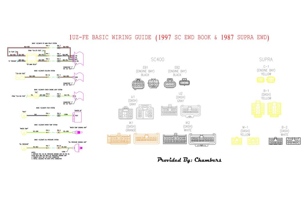
1987 Supra to 1993 LS400 1UZ-FE (This diagram is subject to change, since I have not done a LS400 1UZ-FE swap yet it may change as others give me input)

I used a EWD Book for a 1986.5 Supra (NA Only), and a EWD book for a 1994 SC (300 & 400), and 1997 SC (300 & 400). 1994-1997 SC3/400 from my understanding were transition years in wiring much like our Pre-89 to 89 to Post-89 Supra wiring. So I have started with a 1994 EWD, I just recently picked up a 1997 EWD, and I plan to get a 1996 soon. In my 87 I have a post 1996 (A transition year for the 1UZ) and I noticed a few extra wires on plug IJ1 that needed power but the 1994 book worked just fine.
Since there is so much information I will attempt to post in separate replies, Thanks for looking.
---------- Post added at 10:54 PM ---------- Previous post was at 10:52 PM ----------
Pre-89 NA Toyota Supra:
Interior:
- B-1 – 22 Pins, Yellow in color
o Pin 1 – Black-Yellow in color
§ From “Water VSV” to “Air Mix Control”
o Pin 2 – Red-White in color
§ From “ECT ECU” to “ECU”
o Pin 3 – Red in color
§ From “ECT ECU” to “ECU”
o Pin 4 – Black in color
§ From “ECT ECU” to “ECU”
o Pin 5 – Black-Red in color
§ From “Fuel Pump” to “Check Connector”
o Pin 6 – Green in color
§ From “Circuit Open Relay” to “Air Flow Meter”
o Pin 7 – Black-Light Blue in color
§ From “Circuit Open Relay” to “ECU” and “Starter” (A/T Only)
o Pin 8 – Yellow in color
§ From “ECU” to “Fuel Pump Control Relay”
o Pin 9 – Black-Red in color
§ From “EFI Main Relay” to “Circuit Open Relay”
o Pin 10 – Empty
§ No pin
o Pin 11 – White in color
§ From “A/T Indicator S/W” to “ECT ECU”
o Pin 12 – Black-White in color
§ From “Starter Relay” to “Starter”
o Pin 13 – Light Blue in color
§ From “AC Amplifier” to “ECU”
o Pin 14 – Violet in color
§ From “TEMS ECU” to “Check Connector”
o Pin 15 – Black-Yellow in color
§ From “Cruise Control Clutch S/W” to “ECU”
o Pin 16 – Black-Orange in color
§ From “7.5A IGN Fuse” to “ECU”
o Pin 17 – Black-Orange in color
§ From “Ignition S/W” to “Igniter” and “EFI Resistor”
o Pin 18 – Yellow in color
§ From “Theft Horn” to “Integration Relay No.2”
o Pin 19 – Red-Yellow in color
§ From “Headlight Relay” to “ECU”
o Pin 20 – White-Light Blue in color
§ From “Super Monitor” to “ECU”
o Pin 21 – Red-Green in color
§ From “Super Monitor” to “ECU”
o Pin 22 – Brown in color
§ From “Super Monitor” to “Ground” on Intake Manifold
- B-2 – 14 Pins, White in color
o Pin 1 – Green in color
§ From “A/T” Indicator S/W” to “ECT ECU”
o Pin 2 – Red-Green in color
§ From “ECT Solenoid” to “ECT ECU”
o Pin 3 – Green-Yellow in color
§ From “ECT Solenoid” to “ECT ECU”
o Pin 4 – Yellow in color
§ Dead Ends From Engine Harness to B-2
o Pin 5 – Black in color
§ Dead Ends From Engine Harness to B-2
o Pin 6 – Red in color
§ From “Cruise Control Computer” to “ECT ECU” and “ECU”
o Pin 7 – Light Blue in color
§ From “A/T Indicator S/W” to “ECT ECU”
o Pin 8 – Green-Black in color
§ From “ECT Solenoid” to “ECT ECU”
o Pin 9 – Red-Light Blue in color
§ From “ECT Solenoid” to “ECT ECU”
o Pin 10 – Red in color
§ Dead End
o Pin 11 – Blue-Yellow in color
§ Dead End
o Pin 12 – Red-Black in color
§ Dead End
o Pin 13 – Yellow-Blue in color
§ From “ECT ECU” to “Comb. Meter (SPD Sensor)”
o Pin 14 – Yellow-Black in color
§ From “Check Connector” to “ECT ECU”
- M-1 – 10 Pins, Yellow in color
o Pin 1 – Red-Black in color
§ From “Back Up S/W to “Back Up Lights”
o Pin 2 – Yellow in color
§ From “7.5A Gauge Fuse” to “Back Up Lights”
o Pin 3 – Pink in color (Engine Harness Side)
§ From “ECU” to “Comb. Meter (SPD Sensor)”
o Pin 4 – Black in color
§ From “Igniter” to “Super Monitor”, “ECU”, and “Comb. Meter” (Tach signal)
o Pin 5 – Empty
§ No Pin
o Pin 6 – Brown in color
§ From “Comb. Meter” to “Ground (Intake Manifold)”
o Pin 7 – Yellow-Black in color
§ From “Oil Pressure Sending Unit” to “Comb. Meter”
o Pin 8 – Gray-Green in color
§ From “ECU” to “CEL (Check Engine Light)”
o Pin 9 – Yellow-Green in color
§ From “Water Temp Sensor” to “Comb. Meter”
o Pin 10 – Violet in color
§ From “Defogger Relay” to “ECU”
Engine Bay:
- C-1 – 6 Pins, Yellow in color
o Pin 1 – Black-Yellow in color
§ From “15A EFI Fuse” to “ECU”
o Pin 2 – Black-Orange in color
§ From “ECU” to “EFI Main Relay”
o Pin 3 – White in color
§ From “15A Haz-Horn Fuse” to “Theft Horn”
o Pin 4 – Black-Red in color
§ From “EFI Main Relay” to “ECU”
o Pin 5 – White-Black in color
§ From “AFM” to “Ground (Left Fender)”
o Pin6 – Empty
§ No Pin
---------- Post added at 10:56 PM ---------- Previous post was at 10:54 PM ----------
1994 Lexus SC400:
Interior:
- IJ1 – 14 Pins, Gray in color
o Pin 1 – Green in color
§ From “FPECU” to “Check Connector”
o Pin 2 – Red-Blue in color
§ From “10A HTR Fuse” to “Water VSV”
o Pin 3 – Empty
§ No Pin? Confirm?
o Pin 4 – White in color
§ From “25A Haz-Horn Fuse” to “Haz Horn”
o Pin 5 – Empty
§ No Pin? Confirm?
o Pin 6 – Black-White in color
§ From “IGN S/W” to “Neutral Safety S/W”
o Pin 7 – Empty
§ No Pin? Confirm?
o Pin 8 – Pink in color
§ From “ECU” to “FPECU”
o Pin 9 – Black-Orange in color
§ From “Haz-Horn” to “Theft ECU”
o Pin 10 – Yellow in color
§ From “10A Gauge Fuse” to “Back Up S/W”
o Pin 11 – Empty
§ No Pin? Confirm?
o Pin 12 – Black-Red in color
§ From “EFI Main Relay” to “FPECU” and “Sub o2 Sensors”
o Pin 13 – White-Black in color
§ From “Trac ECU” to “Ground”
o Pin 14 – Red-Green in color
§ From “ECU” to “FPECU”
- IJ2 – 17 Pins, Gray in color
o Pin 1 – Red in color
§ From “Cruise CTRL ECU” to “ECU”
o Pin 2 – White-Red in color
§ From “Cruise CTRL ECU” to “ECU”
o Pin 3 – Pink in color
§ From “Comb. Meter” to “ECU”
o Pin 4 – Green-Blue in color
§ From “Cruise CTRL ECU” to “ECU”
o Pin 5 – Empty
§ No Pin? Confirm?
o Pin 6 – Light Green-Black in color
§ From “Progressive Power Steering ECU” to “PPS Solenoid”
o Pin 7 – Green-White in color
§ From “Stop Light S/W” to “ECU”
o Pin 8 – Empty
§ No Pin? Confirm?
o Pin 9 – Brown-Yellow in color
§ From Cruise “CTRL ECU” to “ECU”
o Pin 10 – Empty
§ No Pin? Confirm?
o Pin 11 – Black-Orange in color
§ From “7.5A IGN Fuse” to “ECU”
o Pin 12 – Black-Red in color
§ From “15A ECU-IG Fuse” to “Trac ECU”
o Pin 13 – Empty
§ No Pin? Confirm?
o Pin 14 – Empty
§ No Pin? Confirm?
o Pin 15 – Empty
§ No Pin? Confirm?
o Pin 16 – Light Green-Red in color
§ From “PPS Solenoid” to “PPS ECU”
o Pin 17 – Blue in color
§ From “ECU” to “Kick Down S/W”
- IK1 – 23 Pin, Orange in color
o Pin 1 – Brown in color
§ From “Left o2 Sub” to “Ground”
o Pin 2 – Green – Yellow in color
§ From “ECU” to “Data Link Connector 2 (TDCL)”
o Pin 3 – Gray-Yellow in color
§ From “ECU” to “TDCL”
o Pin 4 – Light-Green-Red in color
§ From “ECU” to “TDCL”
o Pin 5 – Green-Red in color
§ From “ECU” to “TDCL”
o Pin 6 – Red in color
§ From “Speed Sensor” to “Comb. Meter”
o Pin 7 – Blue-Red in color
§ From “Speed Sensor” to “Comb. Meter”
o Pin 8 – Black in color
§ From “Igniter” to “Comb. Meter (Tach)”
o Pin 9 – Yellow-Green in color
§ From “Water Temp Sensor” to “Comb. Meter”
o Pin 10 – Pink-Black in color
§ From “Trac ECU” to “TDCL”
o Pin 11 – Black-Red in color
§ From “Back Up Light S/W” to “Back Up Lights”
o Pin 12 – Gray in color
§ From “P S/W” to “Comb. Meter”
o Pin 13 – Blue in color
§ From “N S/W” to “Comb. Meter”
o Pin 14 – Green-White in color
§ From “D S/W” to “Comb. Meter”
o Pin 15 – Empty
§ No Pin? Confirm?
o Pin 16 – Green in color
§ From “2 S/W” to “Comb. Meter”
o Pin 17 – White in color
§ From “1 S/W” to “Comb. Meter”
o Pin 18 – Empty
§ No Pin? Confirm?
o Pin 19 – Empty
§ No Pin? Confirm?
o Pin 20 – Yellow-Black in color
§ “Oil Pressure Sensor” to “Comb. Meter”
o Pin 21 – Green-Orange in color
§ From “ECU” to “Comb. Meter”
o Pin 22 – Gray-Red in color
§ From “ECU” to Comb. Meter”
o Pin 23 – Black-Yellow in color
§ From “Air Back Sensor ECU” to “Check Connector”
- IK2 – 25 Pins, White in color
o Pin 1 – White in color
§ From “Right o2 Sub” to “ECU”
o Pin 2 – Blue in color
§ From “Short Pin” to “Trac and ABS ECU”
o Pin 3 – Empty
§ No Pin? Confirm?
o Pin 4 – Light Green-Red in color
§ From “TRAC ECU” to “Comb. Meter”
o Pin 5 – White in color
§ From “TRAC ECU” to “Comb. Meter”
o Pin 6 – Empty
§ No Pin? Confirm?
o Pin 7 – Empty
§ No Pin? Confirm?
o Pin 8 – Empty
§ No Pin? Confirm?
o Pin 9 – Blue-Yellow in color
§ From “ECU” to “Comb. Meter (CEL)”
o Pin 10 – Violet-Red in color
§ From “Oil Level S/W” to “Comb. Meter”
o Pin 11 – Empty
§ No Pin? Confirm?
o Pin 12 – Red-Blue in color
§ From “Left o2 Sub” to “ECU”
o Pin 13 – Red-White in color
§ From “P-Brake S/W” to “TRAC ECU”
o Pin 14 – Empty
§ No Pin? Confirm?
o Pin 15 – Red in color
§ From “10A DOME Fuse” to “TRAC ECU”
o Pin 16 – Yellow-Red in color
§ From “TRAC Cut S/W” to “TRAC ECU”
o Pin 17 – Empty
§ No Pin? Confirm?
o Pin 18 – Red-Black in color
§ From “ABS ECU” to “TRAC ECU”
o Pin 19 – Empty
§ No Pin? Confirm?
o Pin 20 – Empty
§ No Pin? Confirm?
o Pin 21 – Empty
§ No Pin? Confirm?
o Pin 22 – Brown-White in color
§ From “Left o2 Sub” to “ECU”
o Pin 23 – Black in color
§ From “Neutral Safety S/W” to “Comb. Meter”
o Pin 24 – Brown-Black in color
§ From “Comb. Meter” to “Ground”
o Pin 25 – Violet in color
§ From “Short Pin” to “ABS ECU”
Engine Bay:
- EB1 – 8 Pins, Black in color
o Pin 1 – Light Blue in color
§ From “A/C Magnetic Clutch Relay” to “A/C Magnetic Clutch”
o Pin 2 – White in color
§ From “A/C Magnetic Clutch Relay" to "ECU"
o Pin 3 – Black in color
§ From “Neutral Safety S/W" to "Starter Relay"
o Pin 4 – Black-Yellow in color
§ From “30A EFU Fuse" to "ECU"
o Pin 5 – Light-Blue in color
§ From “7.5A TRAC Fuse" to "Traction ECU"
o Pin 6 – Black-Red in color
§ From “Short Pin" to "ABS Actuator Relay"
o Pin 7 – Brown in color
§ From “A/C Ambient Temp. Sensor" to "Ground"
o Pin 8 – Black-Orange in color
§ From “ECU" to "EFI Main Relay"
- EB2 – 3 Pins, Black in color
o Pin 1 – Black in color
§ From “Starter Relay” to “Starter”
o Pin 2 – Black-Orange in color
§ From “Ignition Main Relay" to "Ignition System" and "Fuel Injectors"
o Pin 3 – Black-Red in color
§ From "EFI Main Relay" to "ECU (+B & +B1" and "Misc. Equipment (+B)"
---------- Post added at 10:58 PM ---------- Previous post was at 10:56 PM ----------
1997 Lexus SC400:
Interior:
- IJ1 – 14 Pins, Gray in color
o Pin 1 – Empty
§ No Pin? Confirm?
o Pin 2 – Red-Light Blue in color
§ From “10A HTR Fuse” to “Water VSV”
o Pin 3 – Black-White in color
§ From "IGN S/W" to "Injectors" and "IGN Coil 2"
o Pin 4 – Light Green in color
§ From “25A Haz-Horn Fuse” to “Haz Horn”
o Pin 5 – Red in color
§ From "Vapor Pressure Sensor" to "ECU"
o Pin 6 – Black-White in color
§ From “7.5A ST Fuse” to “Neutral Safety S/W” and "ECU"
o Pin 7 – Black-White in color
§ From "IGN S/W" to "IGN Coil 1" and "Igniters" and "Injectors"
o Pin 8 – Pink in color
§ From “ECU” to “FPECU”
o Pin 9 – White in color
§ From “Haz-Horn” to “Theft ECU”
o Pin 10 – Yellow in color
§ From “10A Gauge Fuse” to “Back Up S/W”
o Pin 11 – Brown in color
§ From "Vapor Pressure Sensor" to "ECU"
o Pin 12 – Black-Red in color
§ From “EFI Main Relay” to “Sub o2 Sensors”
o Pin 13 – White-Black in color
§ From “Trac ECU” to “Ground”
o Pin 14 – Red-White in color
§ From “ECU” to “FPECU”
- IJ2 – 17 Pins, Gray in color
o Pin 1 – Red in color
§ From “Cruise CTRL ECU” to “ECU”
o Pin 2 – Red-White in color
§ From “Cruise CTRL ECU” to “ECU”
o Pin 3 – Orange in color
§ From “Comb. Meter” to "ECU"
o Pin 4 – Empty
§ No Pin? Confirm?
o Pin 5 – Light Blue-White in color
§ From "Cooling Fan ECU" to "Solenoid Valve (Cooling Fan)"
o Pin 6 – Light Green in color
§ From “Progressive Power Steering ECU” to “PPS Solenoid”
o Pin 7 – Green-White in color
§ From “Stop Light S/W” to “ECU” and "TRAC ECU"
o Pin 8 – Empty
§ No Pin? Confirm?
o Pin 9 – Brown-Yellow in color
§ From Cruise “CTRL ECU” to “ECU”
o Pin 10 – Empty
§ No Pin? Confirm?
o Pin 11 – Black-Orange in color
§ From “7.5A IGN Fuse” to “ECU”
o Pin 12 – Black-Yellow in color
§ From “15A ECU-IG Fuse” to “Trac ECU”
o Pin 13 – Green in color
§ From "7.5A TAIL Fuse" to "ECU"
o Pin 14 – Red-Black in color
§ From "Cooling Fan ECU" to "Data Link Connector 1"
o Pin 15 – Black in color
§ From "Solenoid Valve (Cooling Fan)" to "Cooling Fan ECU"
o Pin 16 – Yellow in color
§ From “PPS Solenoid” to “PPS ECU”
o Pin 17 – Empty
§ No Pin? Confirm?
- IK1 – 23 Pin, Orange in color
o Pin 1 – Brown in color
§ From “Both o2 Sub” to “Ground”
o Pin 2 – Green – Yellow in color
§ From “ECU” to “Data Link Connector 2 (TDCL)”
o Pin 3 – Shielded in color
§ From “Shielded Throttle Driver Wires” to “Throttle Driver”
o Pin 4 – Light Blue in color
§ From “TRAC ECU” to “Throttle Driver”
o Pin 5 – Black-White in color
§ From “TRAC ECU” to “Throttle Driver”
o Pin 6 – Red in color
§ From “Speed Sensor” to “Comb. Meter”
o Pin 7 – Light Blue-Red in color
§ From “Speed Sensor” to “Comb. Meter”
o Pin 8 – Light Green in color
§ From “Igniter” to “Comb. Meter (Tach)”
o Pin 9 – Yellow-Green in color
§ From “Water Temp Sensor” to “Comb. Meter”
o Pin 10 – Yellow in color
§ From “CRU CTRL ECU” to “Data Link Connector 1”
o Pin 11 – Light Blue in color
§ From “Back Up Light S/W” to “Back Up Lights”
o Pin 12 – Black-White in color
§ From “P S/W” to “Comb. Meter”
o Pin 13 – Light Blue-Yellow in color
§ From “N S/W” to “Comb. Meter”
o Pin 14 – Green-Yellow in color
§ From “D S/W” to “Comb. Meter”
o Pin 15 – White-Red in color
§ From "Data Link Connector 3" to "Ground"
o Pin 16 – Green in color
§ From “2 S/W” to “Comb. Meter”
o Pin 17 – White in color
§ From “1 S/W” to “Comb. Meter”
o Pin 18 – Black in color
§ From "ECU" to "Data Link Connector 3"
o Pin 19 – Brown in color
§ From "Shielded Black Pin 18 IK1" to "Ground"
o Pin 20 – Yellow-Black in color
§ “Oil Pressure Sensor” to “Comb. Meter”
o Pin 21 – Green-Orange in color
§ From “ECU” to “Comb. Meter”
o Pin 22 – Gray-Red in color
§ From “ECU” to Comb. Meter”
o Pin 23 – Red-Black in color
§ From “Oil Temp/Oil Level S/W” to “Comb. Meter”
- IK2 – 25 Pins, White in color
o Pin 1 – Green in color
§ From “Right o2 Sub” to “ECU”
o Pin 2 – Blue in color
§ From “Short Pin” to “Trac and ABS ECU”
o Pin 3 – Empty
§ No Pin? Confirm?
o Pin 4 – Light Green-Red in color
§ From “TRAC ECU” to “Comb. Meter”
o Pin 5 – White in color
§ From “TRAC ECU” to “Comb. Meter”
o Pin 6 – White in color
§ From "ABS SPD Sensor Rear Left" to "TRAC ECU"
o Pin 7 – Light Green in color
§ From "ABS SPD Sensor Rear Right" to "TRAC ECU"
o Pin 8 – Red in color
§ From "Right o2 Sub" to "ECU"
o Pin 9 – Blue-Yellow in color
§ From “ECU” to “Comb. Meter (CEL)”
o Pin 10 – Violet-Red in color
§ From “Oil Level S/W” to “Comb. Meter”
o Pin 11 – Red-White in color
§ From "Brake Fluid Level S/W" to "TRAC ECU"
o Pin 12 – Red-Light Blue in color
§ From “Left o2 Sub” to “ECU”
o Pin 13 – Black-Red in color
§ From “P-Brake S/W” to “TRAC ECU”
o Pin 14 – Empty
§ No Pin? Confirm?
o Pin 15 – Red in color
§ From “10A DOME Fuse” to “TRAC ECU”
o Pin 16 – Yellow-Red in color
§ From “TRAC Cut S/W” to “TRAC ECU”
o Pin 17 – Black in color
§ From "ABS SPD Sensor Rear Left" to "TRAC ECU"
o Pin 18 – White-Red in color
§ From “Shielded ABS SPD Sensor wire” to “Junction Connector”
o Pin 19 – Empty
§ No Pin? Confirm?
o Pin 20 – Empty
§ No Pin? Confirm?
o Pin 21 – Violet in color
§ From "ABS SPD Sensor Rear Right" to "TRAC ECU"
o Pin 22 – Brown-White in color
§ From “Left o2 Sub” to “ECU”
o Pin 23 – Green-Red in color
§ From “Neutral Safety S/W” to “Comb. Meter”
o Pin 24 – White-Black in color
§ From “Comb. Meter” to “Ground”
o Pin 25 – White-Green in color
§ From “Short Pin” to “ABS ECU”
Engine Bay:
- EB1 – 8 Pins, Black in color
o Pin 1 – Light Blue in color
§ From “A/C Magnetic Clutch Relay” to “A/C Magnetic Clutch”
o Pin 2 – White in color
§ From “A/C Magnetic Clutch Relay" to "ECU"
o Pin 3 – Green-Red in color
§ From “Neutral Safety S/W" to "Starter Relay"
o Pin 4 – Black-White in color
§ From “30A EFU Fuse" to "ECU"
o Pin 5 – Light Blue-Red in color
§ From “7.5A TRAC Fuse" to "Traction ECU"
o Pin 6 – Violet in color
§ From “Short Pin" to "ABS Actuator Relay"
o Pin 7 – Brown in color
§ From “A/C Ambient Temp. Sensor" to "Ground"
o Pin 8 – Black-Yellow in color
§ From “ECU" to "EFI Main Relay"
- EB2 – 3 Pins, Black in color
o Pin 1 – Black in color
§ From “Starter Relay” to “Starter”
o Pin 2 – Black-Red in color
§ From “EFI Main Relay" to "AFM (+B & +B1" and "Misc. Equipment (+B)"
o Pin 3 – Black-Red in color
§ From "EFI Main Relay" to "ECU (+B & +B1" and "Misc. Equipment (+B)"
---------- Post added at 11:00 PM ---------- Previous post was at 10:58 PM ----------
Guides:
1987 Supra to 1997 1UZ-FE
1987 Supra to 1993 LS400 1UZ-FE (This diagram is subject to change, since I have not done a LS400 1UZ-FE swap yet it may change as others give me input)
Last edited: