Tail Lamp Failure Module Information

Kai

That Limey Bastard
Staff member
Yes, i know this thread is probably ancient history by now - but, the LFM in the UK Mk3's is decidedly different looking on the inside, to those already posted:

IMG_2129.jpg


Also - can anyone identify the corroded component between the diode and the fusible link/jumper on the far right hand side? Looks like the same component as is on the left hand side, which LOOKS like a 10 Ohm 1 watt resistor...correct or not? It's labelled 100 J by the looks of it.
 

Kai

That Limey Bastard
Staff member
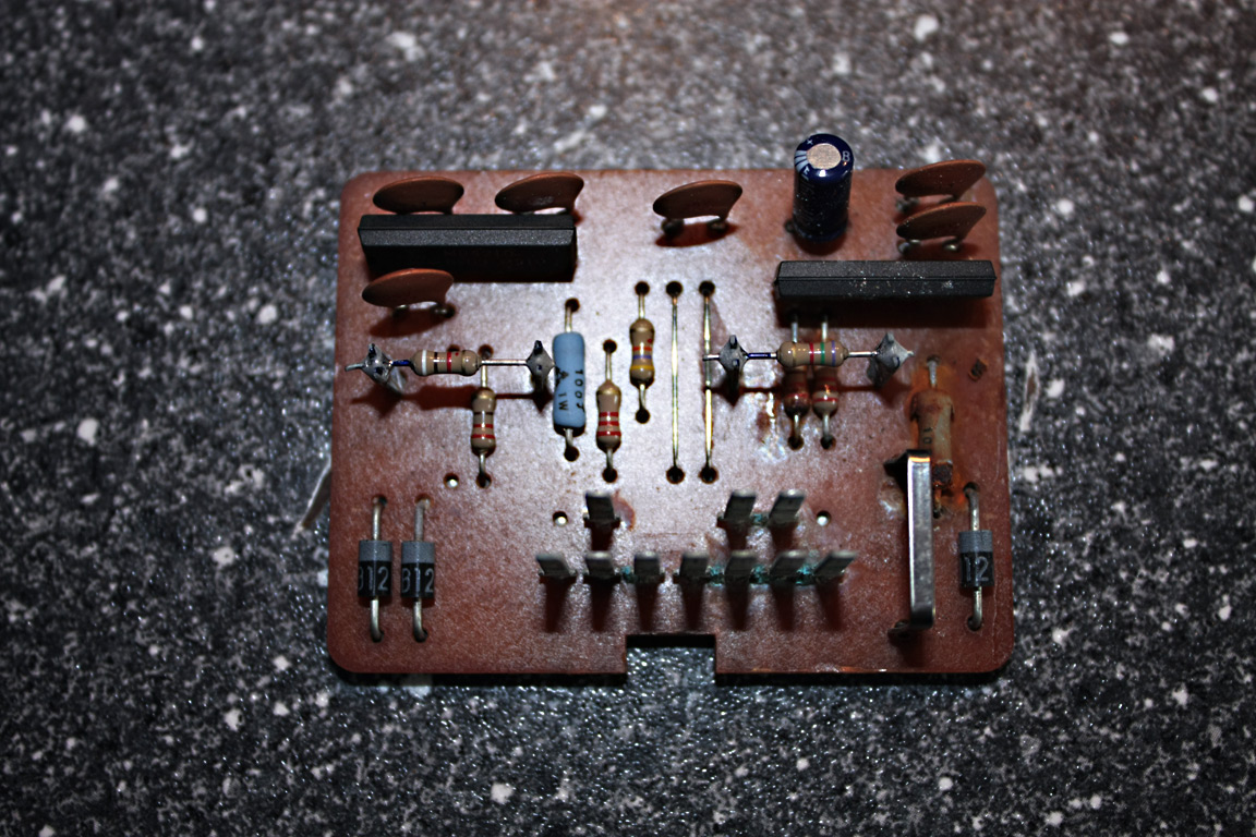
Can Confirm it's a 10 ohm 1 watt resistor in the pictures above.

<Professor Farnsworth>But, gather round, i have good news!</Professor Farnsworth>

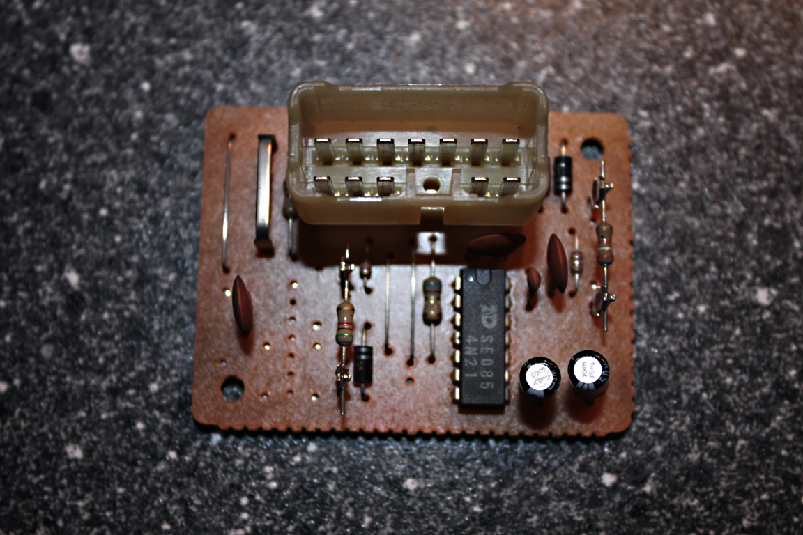
I can *CONFIRM* that the Toyota Lucida Estima (probably the Previa also) Lamp Failure Module (P/N: 89873-28020) is a DIRECT fitment for ours (ie, plugs right in), guys :yes:

The Select-on-Test resistors will probably need to be changed to whatever values were in yours, but, the upshot is, the PCB is of a much newer design (thicker, better construction), uses standard components and only a single 14 pin DIP ASIC. Have included photo's hither.

lucidaestimalfmpcb1.jpg


lucidaestimalfmpcb2.jpg
 

Sullivan

New Member
Jun 22, 2010
7
0
0
San Diego
Is there still any interest in this topic?

I have a 92T with the LED center stop light, interested in modding my module for compatibility with LED replacements for the 1157's.

The pictures at the beginning that show which Rs are R1 and R2 are no longer showing here. However the link to the IC data sheet is very helpful.

FTR (reading previous comments about how it should have been done) I don't see how this could be done without passing the current through the module. It's measuring current, after all, and that requires being in series with the current... unless you clip a Hall-effect sensor onto the wires going to the lamps.
 

supra22

New Member
Apr 15, 2009
9
0
0
Knoxville, TN
Just my two cents...

I did the rewiring on the previous page to eliminate the LFM and the mod worked perfectly!!! This is basically what I did:

GNw/WT to RDw/BL and RDw/WT (these are your brake lights...one for the tail and one for the high mount...GNw/WT is 12V from brake switch)
GNw/RD to GN (this is your tail lights)

I used bare-copper wire jumpers pushed in to the female connector off the LFM, this way I can hook the module back up if I ever wanted to. Don't forget to tape up the connector and wires when finished...or better yet, shrink-wrap the entire thing for a good seal! This will prevent moisture from corroding the contacts as well as shorting the bare-copper to the body frame!

Now, what to do about the Lamp Failure indicator on the dash...I liked someones previous comment about it being a 'Fast-Mode' indicator. I was thinking if I hook this lamp up to my boost gauge and have it illuminate when I reach a certain boost level!!! I will post a mod if I ever figure this out!