This seemed to be a popular thread on the Supraforums and maybe it will help people out here as well.
I've been asked for this several times so I decided to do a write up on how I have done mine.
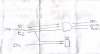
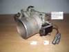
The Nissan TPS uses two 3 wire connectors on it. One is on a short section of harness about 6 inches long and handles the actual throttle position signal and the other made to the body of the sensor is for the idle validation circuit which you also need or you get a code (51 I believe). With the sensor standing up, with the mounting tabs on the right side and the TPS wiring harness coming out of the bottom while your looking at it the top 2 pins in the connector made in the sensor body are your idle validation pins so disregard the bottom pin. Your TPS wiring harness that comes from the bottom of the sensor will terminate at a 3 prong plug and have red, white, and black wires in it. The wires colors correspond with these functions:
Red is the 5 volt input wire
White is the TPS signal wire
Black is the sensor return wire
With the connector lock up the white wire will be in the center, the red wire should be on the left, and the black wire should be on the right. My car is an 88 so I can give wire colors for an 88 Toyota Supra.
Brown is the E2 wire for the sensor return
Blue with a red stripe is the Vc wire for a 5 volt supply
Yellow with a blue stripe is your IDL wire for Idle validation
White with a red stripe is your VTA or throttle position signal
You take your brown E2 wire and branch it into 2 seperate leads. One will go to the idle validation switch and one will go to the TPS harness connector. You can put the one E2 wire(brown) on either the top or second post of the idle validation connector( the one made on the sensor body itself) and the IDL ( yellow with the blue stripe) will go to the other. Then the other E2 wire(brown) will go to the black wire in the Nissan TPS harness, VTA wire(white with red stripe) will go to the white wire in the Nissan TPS harness connector, and the Vc wire(blue with red stripe) with go to the red wire in the Nissan TPS harness connector.
When adjusting this sensor I found the best TPS voltage was around .385 on the sensor check of my S-AFC. This will trigger the idle validation at 3 to 4% throttle which takes alittle getting used to at the pits at the track or light cruise loads but it turned out the code and gets a 100% throttle reading on the afc. I hope this helps any questions I can answer feel free to ask.
Sean
CWF Dyno Services
I've been asked for this several times so I decided to do a write up on how I have done mine.
The Nissan TPS uses two 3 wire connectors on it. One is on a short section of harness about 6 inches long and handles the actual throttle position signal and the other made to the body of the sensor is for the idle validation circuit which you also need or you get a code (51 I believe). With the sensor standing up, with the mounting tabs on the right side and the TPS wiring harness coming out of the bottom while your looking at it the top 2 pins in the connector made in the sensor body are your idle validation pins so disregard the bottom pin. Your TPS wiring harness that comes from the bottom of the sensor will terminate at a 3 prong plug and have red, white, and black wires in it. The wires colors correspond with these functions:
Red is the 5 volt input wire
White is the TPS signal wire
Black is the sensor return wire
With the connector lock up the white wire will be in the center, the red wire should be on the left, and the black wire should be on the right. My car is an 88 so I can give wire colors for an 88 Toyota Supra.
Brown is the E2 wire for the sensor return
Blue with a red stripe is the Vc wire for a 5 volt supply
Yellow with a blue stripe is your IDL wire for Idle validation
White with a red stripe is your VTA or throttle position signal
You take your brown E2 wire and branch it into 2 seperate leads. One will go to the idle validation switch and one will go to the TPS harness connector. You can put the one E2 wire(brown) on either the top or second post of the idle validation connector( the one made on the sensor body itself) and the IDL ( yellow with the blue stripe) will go to the other. Then the other E2 wire(brown) will go to the black wire in the Nissan TPS harness, VTA wire(white with red stripe) will go to the white wire in the Nissan TPS harness connector, and the Vc wire(blue with red stripe) with go to the red wire in the Nissan TPS harness connector.
When adjusting this sensor I found the best TPS voltage was around .385 on the sensor check of my S-AFC. This will trigger the idle validation at 3 to 4% throttle which takes alittle getting used to at the pits at the track or light cruise loads but it turned out the code and gets a 100% throttle reading on the afc. I hope this helps any questions I can answer feel free to ask.
Sean
CWF Dyno Services
")