Need some expert emissions help! 87 B2200 Mazda Pickup

CyFi6

Aliens.
Oct 11, 2007
2,972
0
36
Phoenix
www.google.com
Well I recently bought myself a daily driver, it is a 1987 Mazda B2000 with a 2.2L B2200 engine in it. Its a nice little truck and was what I could afford. It is a bit rough but it will get me around while I work on my real car (Supra). Anywho, the truck failed emissions. Here are the readings.

HC Reading - 2.95
HC Limit - 3.0
HC- Pass
CO Reading-81.24
CO Limit-25.00
CO-FAIL
Nox Reading-3.14
Nox Limit- 4.50
Nox-Pass

CO is obviously very high. HC is high, but still passing. I figure that the engine is overfueling. Here is my issue...
The truck has a computer controlled carburetor. I will start off by saying I know very little about carbs (I know how the work, but I have no practical experience working with them). Add on the fact that there is a computer in the mix along with about 2 miles of vacuum line and I am at a loss where to begin with this thing. From what I understand, the system uses the o2 sensor to adjust a/f ratio using an "A/F Ratio Solenoid" within the carb. The specifics of how it works, I am unsure, but there are several VSV's for different functions such as decell fuel cut off, choke etc.

I need help with one thing specifically. I am looking in the service manual and have come across checking the duty cycle of the a/f solenoid. By looking at this, I can supposedly determine if the truck is in open loop, commanding rich, commanding lean etc. They are asking me to use a dwell meter in the check connector in the engine bay, and measure the duty cycle of the solenoid. I'm a little confused here, I have never used a dwell meter before, and as far as I knew duty cycle was measured in % not degrees? I have attached the illustrations.

"
  1. With engine already at normal operating temperature, start engine and run at 2,000 rpm for 1 minute, then let idle.


  1. Connect a dwellmeter to the A/F check connector (Br/Y wire). Set meter to 4 cyl. scale.
  1. Check the air/fuel solenoid duty cycle (dwell) at the specified rpm (800-850 rpm). Dwell should be in the inspection range and varying.
20°- 70°
NOTE: Adjustment of the idle mixture is normally unnecessary. If the duty cycle is not within specifications, perform the following quick check.
DWELL FIXED BELOW 20°(RICH COMMAND)

The ECU is signaling the mixture control solenoid to "go rich" (engine is idling lean). Try choking the carburetor by covering the air inlet with your hand, fingers slightly open. Gradually close the air gap between your fingers while watching the mixture control dwell. If the dwell increases, check for vacuum leaks at carburetor base and intake manifold. Check float level through sight glass and adjust if necessary. If no problems are found, proceed with idle mixture adjustment. If the dwell does not change while choking the carburetor, check the oxygen sensor and feedback system.

DWELL FIXED ABOVE 70°(LEAN COMMAND)

The ECU is signaling the mixture control solenoid to "go lean" (engine is idling rich or oxygen sensor is contaminated). Try creating a vacuum leak by removing the PCV valve and covering the hose with your thumb. Then gradually uncover the hose while watching the mixture control dwell. If dwell decreases, check for high float level or float bowl flooding (needle valve not shutting off fuel). Check evaporative system for liquid fuel saturation. If float level and evaporative system are OK, proceed with idle mixture adjustment. If dwell cannot be adjusted down, carburetor overhaul and possible mixture control solenoid replacement is indicated. If the dwell does not change when vacuum leak is created, check the oxygen sensor and feedback system.

DWELL FIXED AT 20°(FAIL-SAFE OPERATION)

Check for open oxygen sensor circuit or failed oxygen sensor."

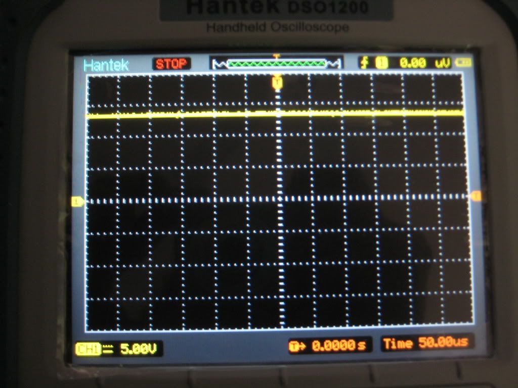
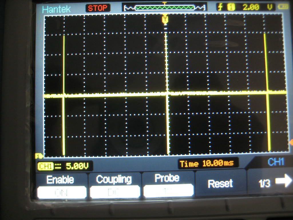
I checked it by setting my meter to 4 cyl dwell. With the engine idling it read about 80 fixed (keep in mind my dwell meter is digital), but the o2 sensor read about .3V. I want to make sure I am doing this test properly before I start trying to trace an open in the o2 circuit.

Things I have already checked include
Plugs- Plugs appear to be brand new
Choke- Working properly, opening fully when warm
Air filter- Appears to be brand new
Float level- Appears proper (level in the middle of the sight glass while idling)
A/F solenoid functionally tests good (clicks when grounded and idle speed changes when grounded while running)
Have not yet checked ignition timing, could incorrect timing cause high CO?
The engine appears to have an aftermarket MSD type ignition system, could this have anything to do with it?

The engine has the original cat (mounted to the manifold) hollowed out, but has a newer cat installed downstream of that.

Any help on this topic would be great, sorry this post is so lengthy.
 

Attachments

  • 41997411.gif
    41997411.gif
    8.1 KB · Views: 6
  • 41997425.gif
    41997425.gif
    16.6 KB · Views: 8

te72

Classifieds Moderator
Staff member
Mar 26, 2006
6,603
2
38
40
WHYoming
Couple things raise minor flags for me:

"Have not yet checked ignition timing, could incorrect timing cause high CO?"
To my understanding, if you're not igniting your A/F mixture at the right time, some of it will remain unburned, correct? I would think that timing would very much affect emissions.

"The engine has the original cat (mounted to the manifold) hollowed out, but has a newer cat installed downstream of that."
Do you have any sort of o2 sensors after the first cat but before the secondary one? Is the secondary cat an OEM thing on this truck? If yes to the first question, and no to the second, I would see about extending that o2 sensor and putting it in the exhaust after that second cat. Might be giving your truck the wrong signals...

All this said, I know VERY little about emissions, living in a state where we don't have testing. Good luck. :)
 

CyFi6

Aliens.
Oct 11, 2007
2,972
0
36
Phoenix
www.google.com
Brad, I attempted to check the timing last night and it appeared to be way advanced, but the lower plastic timing cover is very flimsy and I need to make sure actual TDC matches the printed TDC mark. You are probably right, I would just expect nox to be much higher if my timing was this far advanced (I measured it at about 15 to 20 deg of advance when I checked it as it sits now, and spec is 4-7 deg advance).

I bought the truck from Steven, he told me the truck originally only came with one cat (the one on the manifold) and the lower cat was installed after the top was gutted. I am still looking into this, I am not 100% sure. The factory system only uses one o2 sensor in the exhaust manifold for fuel adjustments as far as I know. I'm fairly certain that catalyst monitoring with another o2 sensor didn't start until 96 with obdII.

Oh yeah, and I forgot to add, this is an IM147 test so all numbers are in grams/mile. The vehicle passed every functional test, the only thing it failed on was CO.

I wish there was no emissions testing for vehicles of this age :(.
 
Oct 11, 2005
3,815
13
38
Thousand Oaks, CA
Ox sensor at 0.3V is indicating lean mixture, and solenoid at 80% is indicating a command to go lean. Either your not measuring the duty cycle right, or the feedback loop is busted.

I'd start by testing that ox sensor on the bench with a propane torch. Given the numbers it should not be reading lean.

I'd also consider ditching the dwell meter for a scope, and actually see what the solenoid signal looks like. You can compute the duty cycle directly yourself.
 

CyFi6

Aliens.
Oct 11, 2007
2,972
0
36
Phoenix
www.google.com
3p141592654;1787390 said:
Ox sensor at 0.3V is indicating lean mixture, and solenoid at 80% is indicating a command to go lean. Either your not measuring the duty cycle right, or the feedback loop is busted.

I'd start by testing that ox sensor on the bench with a propane torch. Given the numbers it should not be reading lean.

I'd also consider ditching the dwell meter for a scope, and actually see what the solenoid signal looks like. You can compute the duty cycle directly yourself.

The "80" reading I took was at idle, the test results are given with no reference to when they were taken, could have been idle, under load etc, the sheet doesn't indicate.

Another thing is my meter was on Dwell measuring in degrees, this part confuses me. You would think the duty cycle should be measured in %, but the manual indicated dwell is the same as duty cycle. Maybe you could enlighten me on this? I have a scope, that is a good idea. I will hook it up and see what it looks like. Also, when disconnecting a vac line from the manifold, the o2 sensor responded appropriately and voltage dropped to near 0.
 
Oct 11, 2005
3,815
13
38
Thousand Oaks, CA
Well, dwell angle is (historically) the angle over which the point are closed (coil charging). For a 4 cylinder engine, there are 4 firings per revolution of the distributor, so the max dwell angle would be 90deg (360/4). Typically it would be ~45deg which is half the available max dwell angle, or 50% duty cycle.

20deg would be 20/90 = 22% duty and 70deg is 78% duty cycle.

A rich ox sensor should 0.45 to 0.8V and lean should be 0 to 0.45V. Maybe you can post up some more reading on the O2 voltage vs duty cycle. I'm still confused cause 0.3V is lean.
 

CyFi6

Aliens.
Oct 11, 2007
2,972
0
36
Phoenix
www.google.com
Alright I need some help 3p lol. I can safely say I don't really know what I am doing here. The engine is running rich, after warming it up and getting it on the road, the o2 is reading around .9v. I hooked up my scope to the solenoid, but don't understand the readings. I am not sure if the scope itself can calculate DC, but this is a screenshot of the solenoid. The reading is fixed- does not change with any RPM, in fact, with the key on engine off it is the same exact reading. Nothing I can do will change it, besides turning off the key. When grounding the solenoid, the engine runs rough and dies, indicating the solenoid itself is working.
Thanks
http://imageshack.us/photo/my-images/847/img2426w.jpg/
I should add, I checked ignition timing and the distributor was 1 tooth off. The timing was at about 20 degrees of advance! I fixed the dist problem and set timing to 6 deg of advance.
There is no fuel jet adjustment for off idle as far as I can see. There is an Idle adjustment screw, which I fiddled with, but it of course did not help any off idle air/fuel ratios. The level in the bowl is in the middle as per the sight glass like it should be.
 
Last edited:

CyFi6

Aliens.
Oct 11, 2007
2,972
0
36
Phoenix
www.google.com
3p141592654;1787572 said:
20deg would be 20/90 = 22% duty and 70deg is 78% duty cycle.
If I am understanding this correctly, as the computer commands a leaner and leaner mixture (less fuel, closing off the solenoid longer), duty cycle increases? The manual above states anything greater than 70% duty cycle indicates a lean command, so the computer is commanding a leaner mix. In other words, the solenoid is energized longer in order to achieve a leaner mixture. Does this mean that this is a normally open solenoid valve? And when I completely ground the solenoid and the engine dies, it is dieing because the engine has gone too lean?

K I think I am getting this now. The system uses a normally open solenoid that defaults to rich in case of a failure, and is closed by the ecu providing ground to the solenoid. The longer the ECU provides ground (higher dc) the less fuel injected. By looking at my scope, it is showing a very high dc (lots of solenoid on time, very little solenoid off time), so the computer is seeing the rich condition and it is closing closing the solenoid off as much as it can. The question is where is all the extra fuel coming from? I know very little about the internals of a carb, any help here would be great, I think I at least got a start on this though (sad, considering it is an 87 pickup we are talking about here).
 
Last edited:
Oct 11, 2005
3,815
13
38
Thousand Oaks, CA
It looks to me like you have the scope ac coupled. It needs to be dc coupled to see a slow square wave which is what I was expecting to see here.

I'm no expert on this system, but if a lean command is more dwell angle, then that would be more time spent with the solenoid drive signal at ground potential. Conversely, lower dwell angle would be more time with the solenoid on.

Assuming the ac coupling is the problem here, then the solenoid is being driven with a ~100 Hz signal, which seems reasonable.
 

CyFi6

Aliens.
Oct 11, 2007
2,972
0
36
Phoenix
www.google.com
Yeah, included a screenshot of that, and another sample. I made sure the attenuation was correct and that the coupling was correct. Signal looks the same as last time. Like before, no matter what I do with the throttle or anything, the signal remains the same, and as long as they key is on it will be the same, even if the engine is not running. As a test, I grounded the check connector (closing off the solenoid) and took it for a drive, it was running very lean and sputtering.
p1791132_1.jpg

p1791132_2.jpg

I also realized that the flat area of the signal graph is representing ~15v, and where the line drops represents near 0v, then I assume the rising voltage above 15v is the high voltage spike from the solenoid coil being turned off. In this case, the computer is leaving the solenoid un-energized (open) for a very long period of time, and very briefly energizing it, resulting in a rich condition. Do I need to start checking all my computer inputs at this point?
 
Oct 11, 2005
3,815
13
38
Thousand Oaks, CA
To summarize.... You posted low dwell (20 deg) is a rich command and the solenoid is energized to add fuel. That implies the solenoid is energized when 12V is applied to the solenoid. The other end of the solenoid coil is therefore grounded it would seem and the ECU sources the current to energize the coil.

You measure mostly 12V to the coil, so the engine is commanded rich. This seems to agree with the emissions data showing a slightly rich condition.

Have you traced the solenoid circuit back to the ECU? Does it show the same signal at the ECU? Have you measured the continuity circuit from the ECU to solenoid? Can you find any documentation showing what a healthy solenoid signal looks like?

I would have expected a diode on the solenoid to control that nasty flyback voltage spike. Maybe that is the root cause of the problem.
 

CyFi6

Aliens.
Oct 11, 2007
2,972
0
36
Phoenix
www.google.com
3p141592654;1791170 said:
the solenoid is energized to add fuel.

I am a bit confused here, maybe I am not understanding how the circuit is set up. I was under the impression that the solenoid is fed a constant B+ with the key on, and the ECM provides a ground to the solenoid to energize it. The check connector, I thought, is on the ground side of the solenoid coil. Because a lean condition can be dangerous, the solenoid is a normally open valve (no current through the solenoid=full fuel flow) in case of a circuit failure, the engine will run rich.

When testing voltage on the check connector, charging voltage (15v) indicates that the computer is not providing a ground, no current is flowing, and the solenoid valve is open to allow fuel flow. When voltage drops to near 0v, the solenoid is energized, current is flowing, allowing the valve to seat and shut off fuel flow. This is why when the check connector itself is grounded, the engine sputters and dies out. Am I correct in what I am saying? From what you said in your previous post seems to indicate that with current flowing through the solenoid coil, the valve is opened thus allowing fuel flow, which is confusing me.

I have not checked the signal from the ECM, and I don't have any idea what a good signal should look like (most people just use an analog dwell meter like the manual asks for, not a DSO. There is limited information in the service manual, but I will do some more digging.). I will verify that I get the same readings directly at the ECM.
 
Oct 11, 2005
3,815
13
38
Thousand Oaks, CA
I was more asking than saying. I don't know this system at all, and don't have a schematic, so I'm just trying to put it together in my head.

So energizing the coil causes a lean condition. Then , I change my summary as follows...

Low dwell (20 deg) is a rich command and the solenoid is off to add fuel. That implies the solenoid is energized when grounded, and the other end of the solenoid coil is 12V. The ECU grounds the solenoid circuit to command the system lean.

You measure mostly 12V to the coil, so the engine is commanded rich. This seems to agree with the emissions data showing a slightly rich condition.

Okay, I would suggest working back to the ECU and verifying the same signal is seen at the ECU pins.

Does this ECU have any built-in diagnostics. Since its pre-1991, it probably only a blinky light (, or less).
 

CyFi6

Aliens.
Oct 11, 2007
2,972
0
36
Phoenix
www.google.com
Alright gotcha. Unfortunately there are no diagnostics on this thing as far as I can tell. There is an "EGR" light on the dashboard that simply illuminates every 60k miles to get you into the dealer for a checkup. To reset the light you swap a connector under the dash lol. So it seems the case is that the computer is commanding a rich condition, even though the o2 sensor is reading .9v. I would be inclined to check for o2 signal directly at the ECM and see if the signal is reaching the computer, that is what I will do first.
Thanks, will update if I find anything.
 

CyFi6

Aliens.
Oct 11, 2007
2,972
0
36
Phoenix
www.google.com
Alright, so the signals are identical when measured directly at the computer. O2 sensor reads .8 or so volts at the pin at the ecu, and the signal out of the ecu is just the same, commanding rich. I tested the water temp sensor and it is OK (.4k ohms at op temp, measured at the ecu). The only sensors left are basically the intake air temp sensor and the water temp switch. I don't know where these are but I am going to try to find them. There are many out puts to this computer but very few inputs, so if something is causing it to stay in limp mode, I really don't know what it is. Any ideas?
 
Oct 11, 2005
3,815
13
38
Thousand Oaks, CA
Water temp switch, I wonder what that does? Maybe its stuck in warmup enrichment.

I'd pop the top off the ECU and see if it has any leaking electrolytic capacitors. I'm not a big fan of part swapping, but without any troubleshooting manual you might just try finding a used ECU in a junk yard as a last resort.

Did the OX sensor respond when you forced it lean?
 

CyFi6

Aliens.
Oct 11, 2007
2,972
0
36
Phoenix
www.google.com
OK well after some more digging I found out that I have a b2200 motor but I have a b2000 computer, hmm. Apparently this isnt much of an issue and it should run fine either way. I already popped the ECU open and looked for any physical signs of damage, there were none. I don't know how to find leaking capacitors, but I know that was a big issue on the similar b2600 ECU's. I already checked the scrap yard and none of the B trucks has a b2000 computer in them, but today I made a different discovery. This is the only diagram I really have to work with, but it should be close enough.
http://econtent.autozone.com:24991/...0c152/80/07/6d/f9//large/0900c15280076df9.gif

After searching around the ignition coil I found a yellow with blue stripe wire tucked into the fender, sitting loose. This appears to be the RPM signal wire that goes to the computer. Since this thing doesn't have a stock tach, I never would have known otherwise that it was disconnected. I have some sort of aftermarket ignition box. It looks like an MSD box but its some other brand. It has power coming from the black with white stripe ignition + wire, which also feeds one side of the igniter in the distributor. The other wire of the distributor is feeding directly into the aftermarket box. From the box, there are two wires Coil + and Coil - powering/controlling the standard canister ignition coil. The yellow blue stripe wire is just hanging there.

I think in order to delete this garbage I need to connect the black with white stripe ig+ wire to the coil positive post as well as the igniter in the distributor, then the yellow/blue stripe wire and the other wire from the igniter both connect to the coil negative post, is this correct? I have a strong feeling this has something to do with my issues.

Another option is to simply connect the yellow/blue stripe wire to the tach output of the aftermarket ignition box, do you think this would work as well?

Why someone would put an MSD ignition on an 85 hp motor is far beyond me...
 

Attachments

  • IMG_2491.jpg
    IMG_2491.jpg
    220.9 KB · Views: 5
Last edited: