Fuel pump upgrade & wiring 12v

isnms

United States of America
Mar 30, 2005
2,145
0
36
Oklahoma
i80.photobucket.com
Just spoke with Kenne Bell. Boost-A-Pump is not a suitable solution, by itself, for lo/hi speed. It's lowest regulated output voltage is 13.5v. So it is equivalent to full time 12v rewire.

jdub said:
If you could build a PWM circuit that accepts an analog input (say Ne or Boost psi) to control pump speed, it might be made to work.
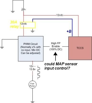
I'd like to see if it could trigger off a boost sensor. I have one on my zeitronix.
 
Last edited:

jdub

Official SM Expert: Motor Oil, Lubricants & Fil
SM Expert
Feb 10, 2006
10,730
1
38
Valley of the Sun
I think I understand what he's doing now:
John Cribb said:
The User #1 output map (see screen shot below) starts at 60% for 0% Load, and increases linearly up to 100% at 31.25%, then stays at 100% for the remainder of engine load. In this way, the fuel pump receives about 8-8.5v at idle, and this increases to 12-13v at 31%. Then when the engine hits 15psi boost, and 3000 RPM, I have the BAP configured to kick the voltage up to 16v, just to be sure there’s no fuel starvation at higher boost.

I think he's using the SSR controlled by the AEM as a simple PWM to control stock voltage/current at lower engine load up to 31% where pump output goes to 100% (stock) output...actually lowers pump output at 31% or less load. Then he's using the BAP to step voltage up beginning at 15 psi boost/3000 RPM to increase FP output...the SSR is already allowing 100% pass through at this point.

figgie...please correct me if I do not have this right ;)
 

figgie

Supramania Contributor
Mar 30, 2005
5,224
16
38
49
Twin Cities, Minnesot-ah
jdub;1110903 said:
I think I understand what he's doing now:


I think he's using the SSR controlled by the AEM as a simple PWM to control stock voltage/current at lower engine load up to 31% where pump output goes to 100% (stock) output...actually lowers pump output at 31% or less load. Then he's using the BAP to step voltage up beginning at 15 psi boost/3000 RPM to increase FP output...the SSR is already allowing 100% pass through at this point.

figgie...please correct me if I do not have this right ;)

jdub

right on the money :)

the only thing I might do different is run the KB BAP 16v full time and PWM that. Takes the Enable circuit out and just PWM more duty cycle range.

"picture" of his circuit. Forgive the crudeness of it. I only have visio at work :(
 

Attachments

  • lextreme-Circuit.jpg
    lextreme-Circuit.jpg
    45.6 KB · Views: 66

jdub

Official SM Expert: Motor Oil, Lubricants & Fil
SM Expert
Feb 10, 2006
10,730
1
38
Valley of the Sun
Perfect! A picture is worth a 1000 words ;)
Thank you!

figgie - do you think it would be possible to build a PWM circuit that would allow what's in post #21 above on a stock TCCS?
(i.e. scale pump output with boost or RPM)
 

figgie

Supramania Contributor
Mar 30, 2005
5,224
16
38
49
Twin Cities, Minnesot-ah
isnms;1110879 said:
I'm interested to know if this can be implemented with the TCCS (and how to) or does it require going stand alone (AEM)?

It can actually but the BAP will complicate matters.

the diagram attached is for PWM the fuel pump instead of using inline resistor as stock and controlled by the TCCS. Does not go above 13.8v.

The PWM circuit can be purchased or built.

jdub;1110927 said:
Perfect! A picture is worth a 1000 words

Thank you!

figgie - do you think it would be possible to build a PWM circuit that would allow what's in post #21 above on a stock TCCS?

picture attached ;)

if using a BAP. I would put it to feed the PWM circuit so the PWM circuit is seeing 16v instead of the 13.8v. Then you PWM the 16v as before (alone done within the PWM circuit). :)

With the AEM. The outputs are voltage static (ie can not change the voltage on the fly?)

If you really want, you can attach a map sensor (observe voltages) and have it output the voltage to the control portion of the PWM.
 

Attachments

  • Stock-TCCS.jpg
    Stock-TCCS.jpg
    29 KB · Views: 28
Last edited:

jdub

Official SM Expert: Motor Oil, Lubricants & Fil
SM Expert
Feb 10, 2006
10,730
1
38
Valley of the Sun
My AEM docs (30-1130) only shows 2 PW outputs...there are 2 additional (#7 & #8) injector outputs that you might be able to adapt.

On the TCCS, you can get a PWM commercially that will scale from minus to full output based on voltage rise from a MAP sensor?
 

isnms

United States of America
Mar 30, 2005
2,145
0
36
Oklahoma
i80.photobucket.com
SWEET!!! Thanks figgie!!
Will the PWM handle the full amp draw of a mkiv pump?
I've got so much to learn about this. Hope you don't mind some dumb questions.

jdub said:
On the TCCS, you can get a PWM commercially that will scale from minus to full output based on voltage rise from a MAP sensor?
something like this?
p1110949_1.jpg
 

figgie

Supramania Contributor
Mar 30, 2005
5,224
16
38
49
Twin Cities, Minnesot-ah
jdub;1110945 said:
My AEM docs (30-1130) only shows 2 PW outputs...there are 2 additional (#7 & #8) injector outputs that you might be able to adapt.

On the TCCS, you can get a PWM commercially that will scale from minus to full output based on voltage rise from a MAP sensor?

the first link i posted.. The PWM output Duty Cycle is based on input voltage which happens to be controlled by a rheostat. :) A diode inline to numerous inputs with diff resistors will also accomplish that ;)

http://www.mouser.com/Search/ProductDetail.aspx?qs=WrllwUZn0BofhdTdnV%2fO4g==

on leg R8 - VR1. That is the rheostat that controls DC (and it works quite well to 100% unlike most that go to 80%.)

The custom made one, depends on the MOSFET load capabilities. I am not sure if the Solid state relay can be triggered directly from this. If it can push a SSR directly, it will make the current capacity of the PWM irrelvant :)

Mouser is your friend for all electronics ;)
 

figgie

Supramania Contributor
Mar 30, 2005
5,224
16
38
49
Twin Cities, Minnesot-ah
isnms;1111069 said:


30 amps max.. Relying on two mosfets. Here is my concerns with that.

If one mosfet goes, the other one cascades in a death of firey glory. Yes FIRE. I have never been a fan of parallel mosfets unless a fail safe is built in that cuts the power if one of the FETs fail.

Now with that one, you can control the PWM manually to a fuel pump. Would need lots of rework to get it to work right.

here is the other issue. What ever the motor/pump max Amp draw is, double to triple it for the initial inrush current at startup.
 

isnms

United States of America
Mar 30, 2005
2,145
0
36
Oklahoma
i80.photobucket.com
Thanks shaeff, that’s a good link. I have nixed BAP from my consideration.

I am interested in the PWM and with 100% activation on as set boost level. But the stuff figgie said about “FIRE” and “parallel mosfets” tells me I’m probably not going to be able to design the PWM myself. I may have to go for the Weldon jdub linked. I can’t find any technical documentation on it though. How full current is enabled for example.

Anyway, this is what I am thinking up: figgie – don’t shoot me for using your diagram ;)

If hi is enabled from a ground signal:

[thumb]http://i80.photobucket.com/albums/j187/isnms/Supra/Stock-TCCS1_gndEnable.jpg[/thumb]

If hi is enabled from a positive signal:

[thumb]http://i80.photobucket.com/albums/j187/isnms/Supra/Stock-TCCS1_posEnablex.jpg[/thumb]
 
Last edited:

isnms

United States of America
Mar 30, 2005
2,145
0
36
Oklahoma
i80.photobucket.com
I thought I had read that with modifications the TCCS calibration of switch will be out of sync of where it needs to be.

Now if this is wrong, I would like correct information.
 

isnms

United States of America
Mar 30, 2005
2,145
0
36
Oklahoma
i80.photobucket.com
Last edited:

figgie

Supramania Contributor
Mar 30, 2005
5,224
16
38
49
Twin Cities, Minnesot-ah
isnms;1114891 said:
Ok, looking at the Weldon Dial-A-Flow instructions, the hi speed switch is a pos enabled, so I changed my diagram:
[thumb]http://i80.photobucket.com/albums/j187/isnms/Supra/Stock-TCCS1_posEnable.jpg[/thumb]
I also see where I was unnecessarily complicating the wiring.

edit: I'm thinking activate HI with a set boost pressure.
Could you also get a higher pressure switch and activate HI on a set fuel pressure?
Which would be better?

Well in my honest opinion. The stock system works fine. Fuel pressure should be used for monitoring or a cut off switch but in high hp. I would forgo the cut off switch. To use it as a base for kicking the fuel pump into high is asking for trouble.

There would be two things that would need to be used, perhaps getting away with one.

TP position & MAP. Add RPM if you are standalone. MAP would be the simplest. At x psi, turn on. The only issue is if on stock. You want to stay as close to the stock configuration as possible. Meaning RPM based control not pressure.

Also keep in mind that the ECU keeps the Fp signal ON to use the Resistor. With the Fp signal off it bypasses the resistor as shown in the TSRM

http://www.cygnusx1.net/Supra/Library/TSRM/MK3/manual.aspx?Section=FI&P=70
 

isnms

United States of America
Mar 30, 2005
2,145
0
36
Oklahoma
i80.photobucket.com
figgie;1115621 said:
Well in my honest opinion. The stock system works fine.

Okay, that brings me back to my original question:
So with all that said; Help me plan my wiring.
• leave stock circuitry
• run 12 volt full time, upgraded wiring
• run upgraded wiring with hi/lo switching still in place. resistor size?

I prefer to use the mkiv for Toyota quality/reliability.​

Are you saying the stock resistor setup and wiring will drive the mkiv pump just fine?

If so, that would be great. I can get to installing my new pump :)


Note: For this thread purpose, I am only trying to get the circuitry/wiring correct.
I know about removing the j-tube restriction, even afpr, which I also have, an aeromotive.
 
Last edited:

isnms

United States of America
Mar 30, 2005
2,145
0
36
Oklahoma
i80.photobucket.com
figgie: Are you saying the stock resistor setup and wiring will drive the mkiv pump just fine?


I know they're on practically every other thread about putting in a walbro, the guys that say you must do the 12v mod. The guys that also chime in and say it is not needed also make an appearance. Where are you guys? If you have a conviction that you must do the 12 volt fuel pump upgrade wiring, let me know why.

If stock wiring is going to heat up and catch fire because it can not handle the draw of a mkiv tt pump I want to hear your experience. Does anyone have this experience??

Thanks jdub and figgie for your input.
 

figgie

Supramania Contributor
Mar 30, 2005
5,224
16
38
49
Twin Cities, Minnesot-ah
isnms;1119545 said:
figgie: Are you saying the stock resistor setup and wiring will drive the mkiv pump just fine?


I know they're on practically every other thread about putting in a walbro, the guys that say you must do the 12v mod. The guys that also chime in and say it is not needed also make an appearance. Where are you guys? If you have a conviction that you must do the 12 volt fuel pump upgrade wiring, let me know why.

If stock wiring is going to heat up and catch fire because it can not handle the draw of a mkiv tt pump I want to hear your experience. Does anyone have this experience??

Thanks jdub and figgie for your input.

sorry about the tardiness in response. No computer at home and being a holiday weekend..... ;)

What "camp" I am in? Neither!

I like to know how things work. I also like to know why Toyota did what they did (see me harping on the EGR threads). Why did toyota do what they did, both here and in the oversea's Supra?

Ask those people above why? And they won't give you facts. Just opinionated non-sense (which is my opinion of there opinon they take as fact) or I heard yada which does not answer the more important question, WHY?

The stock wire catch fire? I can see that but only if the wire is so bad and the ground is horrible.
 

isnms

United States of America
Mar 30, 2005
2,145
0
36
Oklahoma
i80.photobucket.com
Ok, I want to test my stock wiring to see if it will handle the mkiv pump current draw. Do I:

• Do a continuity test from the fuel pump relay to the pump? (or which point to which point) and what would be an acceptable resistance and what would be to much requiring a rewire?

- or -

• Do a voltage drop test from the fuel pump relay to the pump? (or which point to which point) and what is an acceptable drop and what would be to much requiring a rewire? And this would have to be done after installing the pump, reassembling everything. Then if it fails the test, have to take everything apart again to rewire - right?