89 Turbo LED project

89TurboPC

New Member
May 10, 2007
75
0
0
Beach Cities, SoCal
Well, many of you are into engine/turbo and other stuff for speed. I'm on other hand are more into electronic related. I bought this car since 1995 and been thru BHG like many of you, but the engine is still consider 99% original other than BHG related fixed. Before this Supra, I also had a 85 that I bought in 92 and sold it in 96.

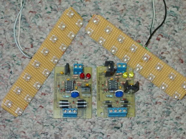
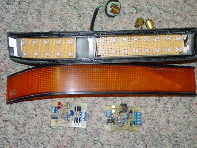
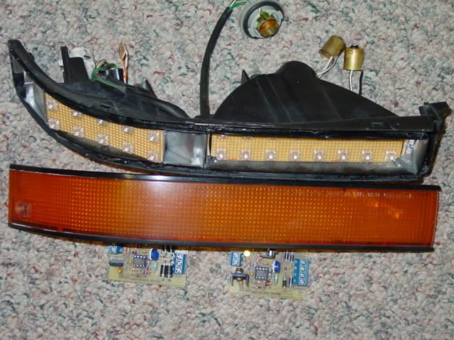
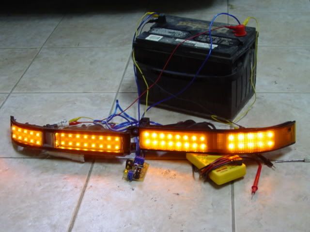
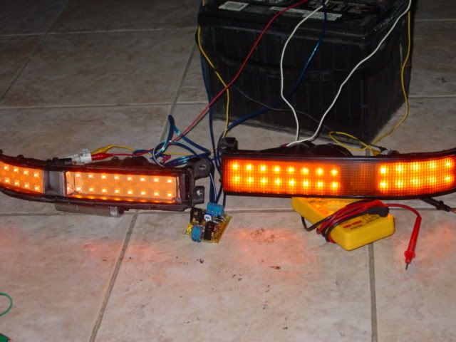
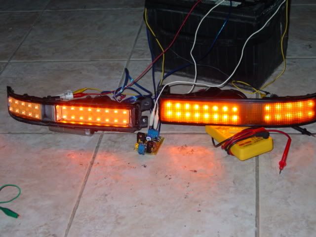
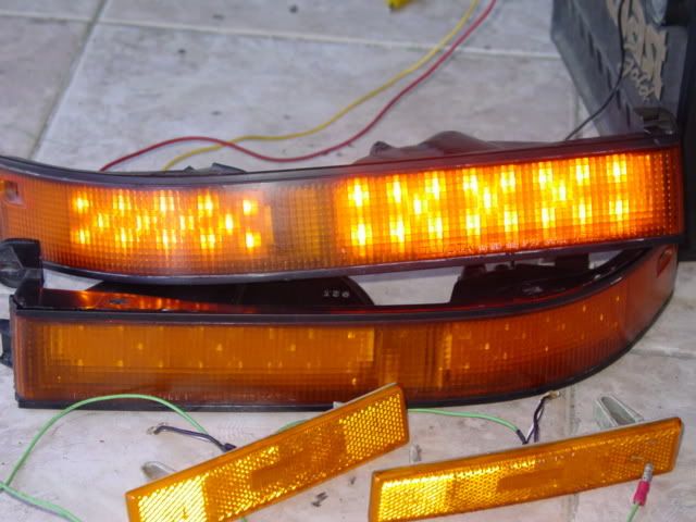
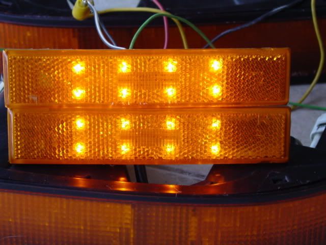
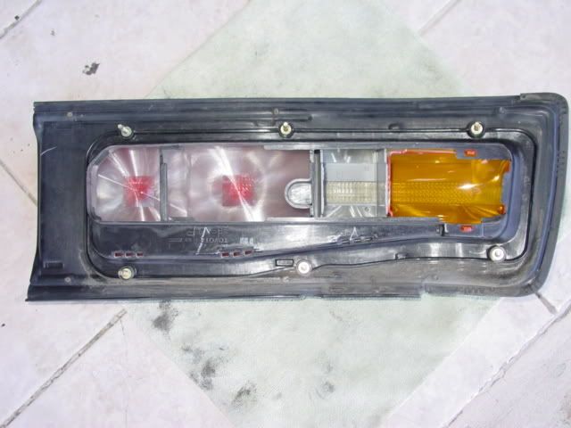
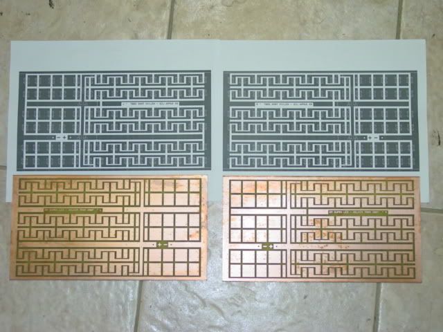
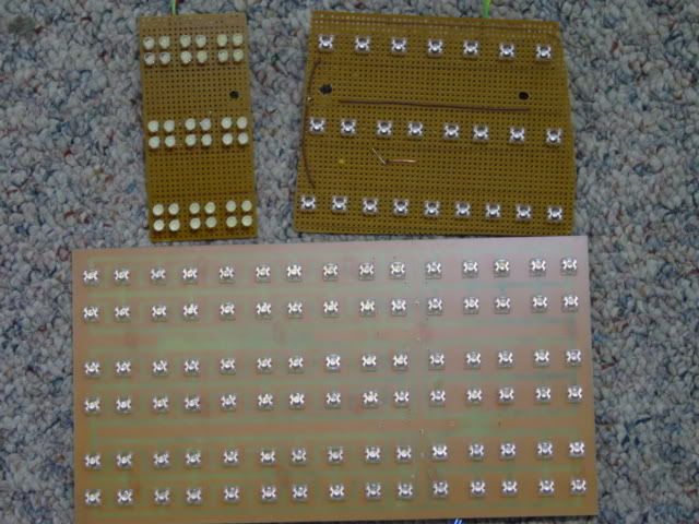
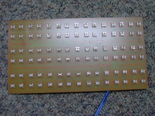
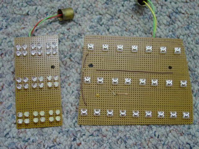
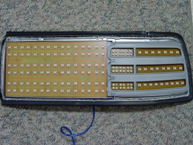
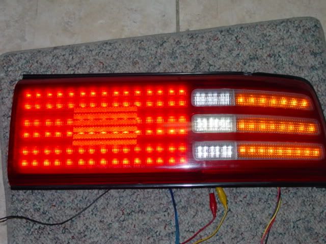
So there it is. My carPC project is completed (other than software update). It's time for me to play around with LED. First thing is external lighting. Once that complete, I will tackle instrument cluster and other internal lighting.

I plan to finish the project and then posted here, but someone already find out on hidplanet.com so I just post in case someone want to work along. There are more discussion about problem I encountered over at hidplanet: MK3 Supra Turbo LED setup project.

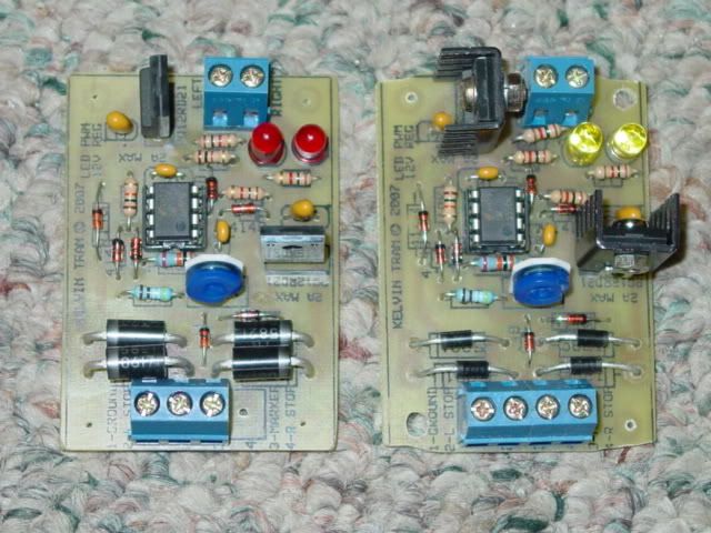
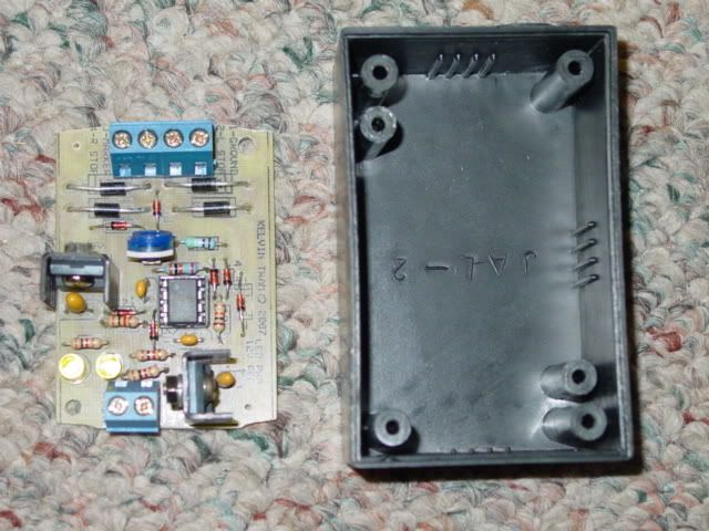
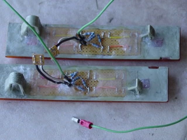
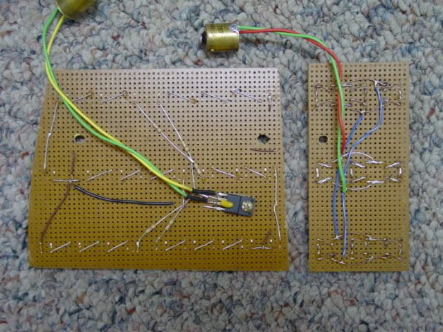
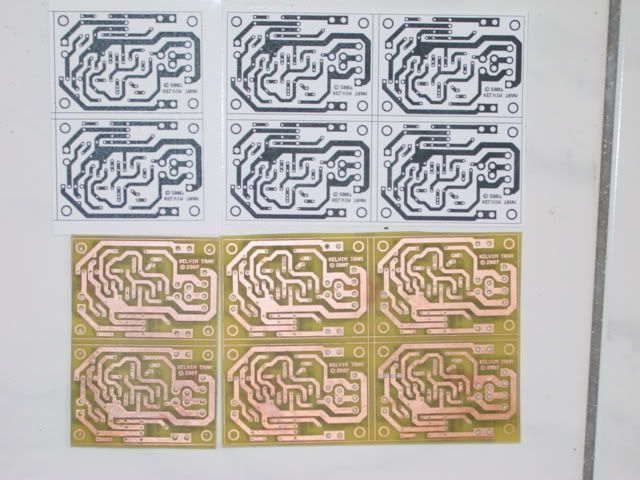
Before anything done, I build the PWM (Pulse Width Modulator) that is used to dim the rear running lights and full brightness when brake is on.
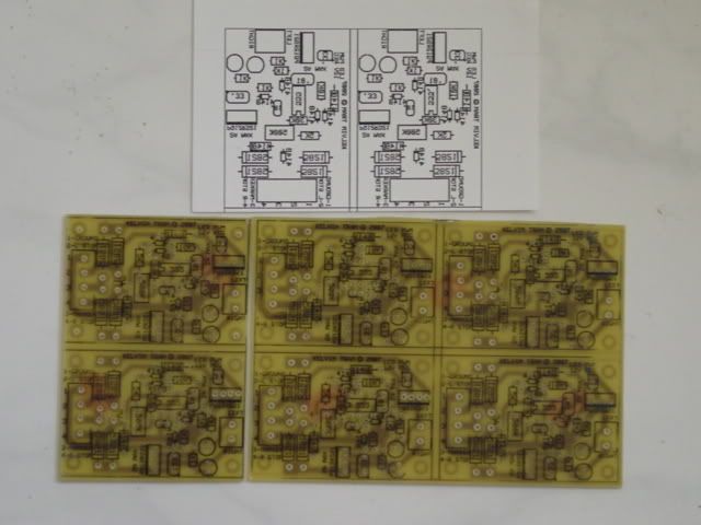
This is the circuit. The drawing is similar to some design you find on the web, but the circuit is design base on information I found on hidplanet LED forum. There are many knowledge people in that forum that put great amount of time contribute to the design of the circuit.
 

Attachments

  • PWMSchema.GIF
    PWMSchema.GIF
    11.7 KB · Views: 263
Last edited:

89TurboPC

New Member
May 10, 2007
75
0
0
Beach Cities, SoCal
From the circuit above, working with expressPCB, this is the result.

Bottom of the PCB and the lazer print out. There are 6 of them. I may have 2 or 3 left when I finish and probably sell it back to those who want. But as of now, nothing is for sale.
I use iron transfer method and Ferric Chloride to etch the board. The paper use is the popular Stapples Photo Paper.
Click on the image for larger photo.


Top or silkscreen of the PWM. The same paper is use for silkscreen.


2 PWMs are finalized. One is 9V and the other is 12V. 9V @ 1A is for the front signal. I opted to have DRL as well which being dim by PWM. 12V @ 2A is for the back running light and brake. Dedicated turn signal will be regulated with stand alone 9V. Why I use 9V for turn signal instead of 12? Well, my meter only read between 10-11V instead of 12+V. 9V regulated will be ok on the safe side ;)


Each of those regulator will power 16 amber LED running at 30mA.


This is what the whole light housing look like. There are 1 tiny screw at the end of the housing (marker end). Use a needle noise plier to unscrew/pull it out. Once the screw come out, you can use oven heat to separate the lens if you wish. 280 degree F for about 5 minutes (make sure to check often). I use hair dryer at low speed and high heat. Come out nice and clean after 4-5 minutes.


The smaller board with 10 LEDs is the amber marker light. Those run at car voltage (12.8V the same voltage as factory 3rd LED brake light). I know the brightness will be different, but what the hell.


Because the PWM will be outside of the cabin, I need a protective case of it in case of rain/car wash and other unknown objects.


I want to thanks a few fellow over at hidplanet especially azdave, CoZZm0_AU, DarkAngel, and many others for the contribution to the design of the PWM.
 
Last edited:

89TurboPC

New Member
May 10, 2007
75
0
0
Beach Cities, SoCal
These shots are taken in the garage. One of the light has reflector on while the other isn't.
The following 2 pictures are with the 500K turn about 1/2 way. I still need to adjust the brightness during the day when it is actually in the car.


The following 2 are at max brightness for turn signal.


Last edited:

89TurboPC

New Member
May 10, 2007
75
0
0
Beach Cities, SoCal
The turn signal and drl combination isn't working so well as DRL. I remove the PWM and have the turn signal by itself.
I modify the marker (smaller 10 led portion) to function as DRL by wire it to the ignition and marker light separate by diodes. Also I add 4 more led so the board look more fill now.
So the current configuration is marker/drl + signal.

The small side markers also get LED. I also wire it to be use as signal/marker.


side front marker is combined to be marker/signal.


The back of the marker. Ugly but, what the hell. ;)
 
Last edited:

89TurboPC

New Member
May 10, 2007
75
0
0
Beach Cities, SoCal
Ok some may ask how do I deal with turbo/hyper flash?
I went to local junk yard and get couple flashers from an early (80-85) BMW 3/5 series. Those flasher make by Hella (like most BMW lighting stuff) that came with an Amtel U643B chip. What special about U643B chip? Bulbs failure feature can be defeated. :thumbup: To disable bulb failure detection circuit, cut the trace to pin 7 of the chip.

This is the BMW flasher and the stock 89 Supra flasher. They are PIN compartible. ;). You can see the part number for both flashers. NOTE: pre 89 Supra use different flasher. Pre 89 use #81980-16010 flasher and 89+ use 81980-12070 flashers are not interchangeable. Basically, all Toyota cars of the same year use the same flasher.


Inside of the 2 flashers. You can tell which one is which.


Close up of the BMW flasher internal and the feature chip.


Can you tell where the trace being cut? Thanks to a sharp utility blade.


The BMW flasher flash a little faster than I want it to. I measure the resistor that control the flash rate that came to about 130K ohms. With a 160K ohm, the rate is perfect for me. I don't have one in hand but a 500K POT in hand so I use a POT instead. Adjustable flasher anyone? ;) The picture below is the 2 BMW flasher, one with a default resistor (130K) and the modified adjustable flasher.


Anyway, the front end is basically finish. ;)
 
Last edited:

89TurboPC

New Member
May 10, 2007
75
0
0
Beach Cities, SoCal
Alright, with the front end is completed, it's time to move to the rear tail light.

There are 2 bulbs for marker and brake light, 1 bulb for backup and one for flash. They all has diffuser inside. Signal has an additional yellow lens insert.


The Supra tail light has a total of 7 screws that hold the lens to the housing in addition to the sticky glue. 6 of them can be easily find because they are just next to the bigger screws. This is how they look like


The 7th screw is on the side. If you look at the Left light, it will be on the upper left and upper right on the Right light. See the picture below. The screw is pointed by the pen. You can easily unscrew this one with a plier.


Because I want to re-use those screw, I take my time to unscrew them. The picture below is the tools I use to flatten the plastic around the screw so I can unscrew them with the plier.


This is how it look after the plastic was removed


This is how I unscrew those screws.


One out, 5 more to go.


After all of the screw removed. Turn on an oven and put on bake at 280 F. When the temperature reach 280F, turn off the oven and put the tail light in there on an aluminum foil on top of a bake pan. Keep the oven door partially open and keep an eye on it. After about 7 minutes, I rotate the light around because the light is TOO big for the oven. Keep it in there for another 3-4 minutes for a total of about 10-11 minutes. Take the light out and put it on a tower (to prevent scratch) face down. Use paint scraper or flat head screw driver and start separate the lens. Do not force it, If it doesn't feel easy, try different spot or put it back in the oven for another 1-2 minutes.
Take me about 5 minutes to separate them and this is what it look like.


Alright, time to work on the board for those leds.
 
Last edited:

89TurboPC

New Member
May 10, 2007
75
0
0
Beach Cities, SoCal
Thanks guys.
This is what the rear marker/brake led board will look like. There are 90 of those led running 5 in series with 33ohm resistor which is about 37-40mA thru each led.
I already etch the board and drilling the holes, but couldn't find the freaking reader to upload the pictures.
 
Last edited:

shaeff

Kurt is FTMFW x2!!!!
Staff member
Super Moderator
Mar 30, 2005
10,585
9
38
Around
^ seriously. this stuff is pretty sweet! i don't have the electrical expertise to pull off something like this. :( (yet- i plan on taking some courses, though)

-shaeff
 

89TurboPC

New Member
May 10, 2007
75
0
0
Beach Cities, SoCal
From the layout above, this is the result.

Already etched.


Close up


LED to be used and the proto board.


Another close up of the board


The board will have 90 LED. Imagine, you have to drill all most 800 holes for the LED and resistors with a dremel. That's suck.
 
Last edited:

88YotaTurbo

New Member
Feb 26, 2006
658
0
0
39
Wolcott, Ct.
awesome work and thank you for laying out some bricks for me to follow.
I will be doing the same soon but changing the orientation of the rear led's to better match pre 89 light housings.
SUBSCRIBED ***
 

89TurboPC

New Member
May 10, 2007
75
0
0
Beach Cities, SoCal
All the led are in.


The brake/marker


Back side of the brake/marker


Turn signal and backup.


Back side of turn signal and backup.


Brake/marker is 12V regulated and dim by PWM.
Signal is 9V regulated as you can see the regulator is mount to the board.
Back up is straight to car voltage without resistor nor any regulator. Why do I do that? Well, I'm lazy and I have been using it like that (doom light) for the pass couple months without problem. Giving the amount of time the led will be on isnt' much for them to burn out.
 
Last edited:

89TurboPC

New Member
May 10, 2007
75
0
0
Beach Cities, SoCal
Into the light housing.


They actually work ;). The picture is a little angle cuz I can't stand straight at the light as you know why. The brake/marker is DIMMED as it will be marker brightness.


With the lens on (still on marker brightness).


Oh yeah, with full brightness on (brake)


Now I need to find a way to mount the board into the housing either permanently or semi-permanent.
 
Last edited:

BorHor

2JZ-GZE
Jan 10, 2006
6,181
1
0
35
San Jose, CA
really nice work. I am still working on my front signals. I forgot how much time school takes away. I hope I can get all my exterior lights done by the end of this year though.
 

88YotaTurbo

New Member
Feb 26, 2006
658
0
0
39
Wolcott, Ct.
still awaiting delivery of my led's. I went the cheaper route and bought from ebay. they were 100 15000mcd white leds for $2 plus 8 shipping
 
Last edited:

89TurboPC

New Member
May 10, 2007
75
0
0
Beach Cities, SoCal
88YotaTurbo said:
still awaiting delivery of my led's. I went the cheaper route and bought from ebay. they were 100 1500mcd white leds for $2 plus 8 shipping

Well, sometime you find some good deal on ebay as well. Normally, I don't really count any words on the seller description.
The white led I got for like 2 buck + 6 s/h for 100. For some seller with the same led some list as 13K while other listed as 20K. I mean com'on, a high 20K cmd rating with a narrow viewing angle + low current flow is just as good as on with 1k rating.
The amber led I bought from quickar electronic for 10 cents a piece. Those are decent led and not as good as lumileds by Phillips but not cheap a$$ one.
The red/orange led are the one make by HP lumiled and cost as much as 15 cents (in bulk buy).