Guide : Installing gauges

JSeaman

SM Official Expert: Guide Author
SM Expert
May 26, 2009
216
0
0
Derbyshire, UK
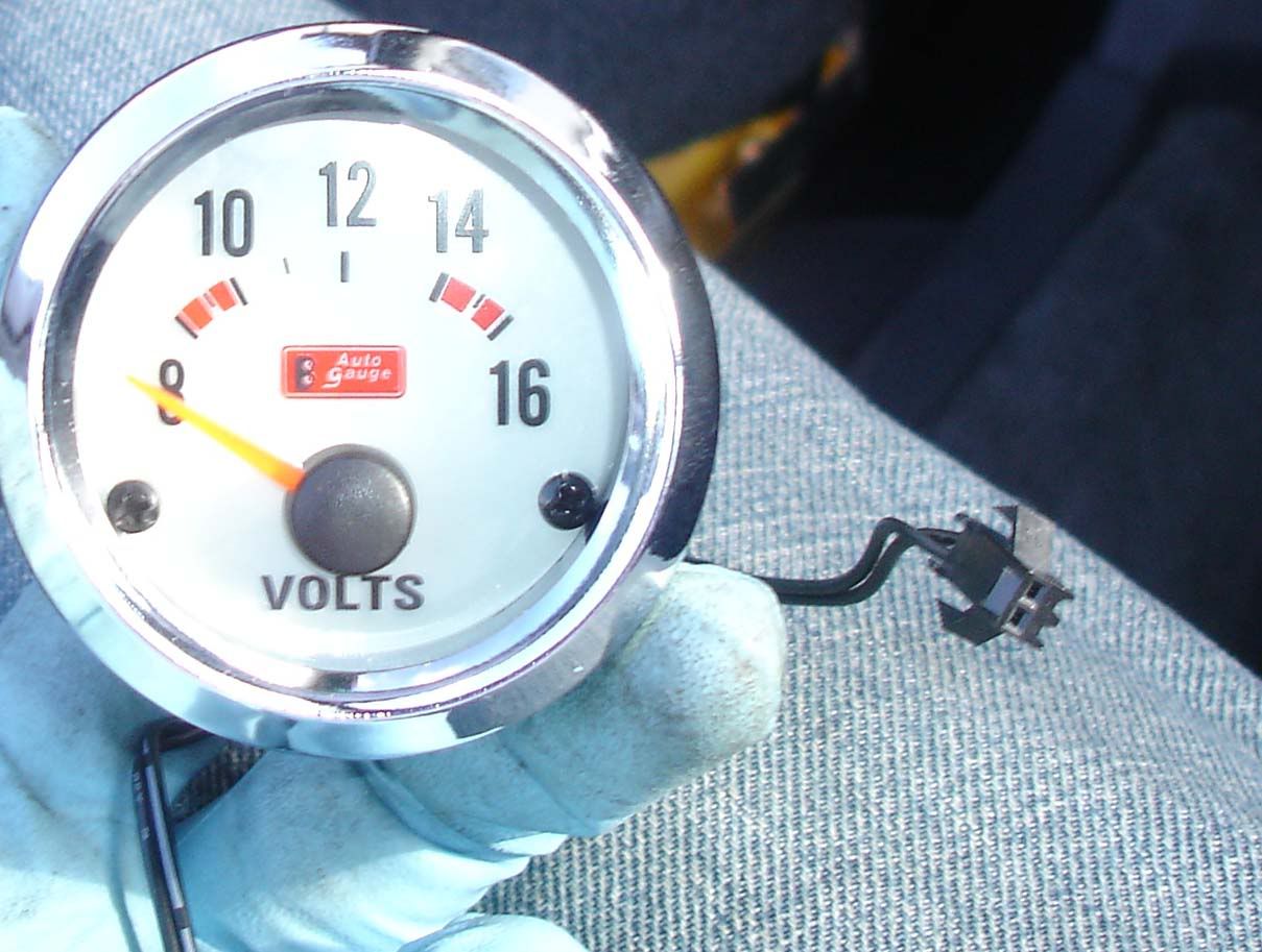
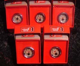
For the purpose of this guide I'm installing boost and voltage gauges. I will also be adding oil pressure + temperature, water temperature, EGT and possibly a wideband in the future so I had to do the groundwork to run all of these gauges. Here are the 5 gauges I have waiting to install:

p1329344_1.jpg


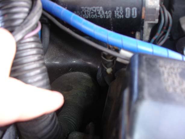
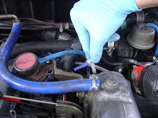
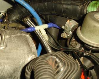
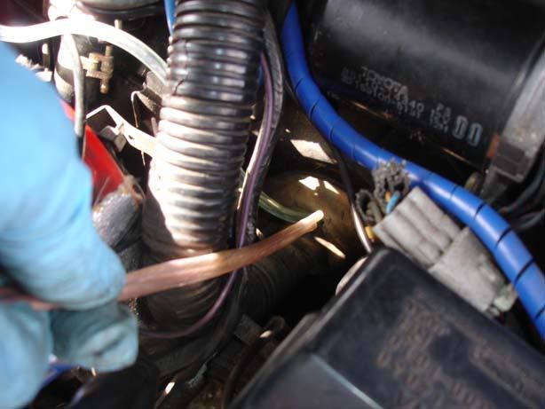
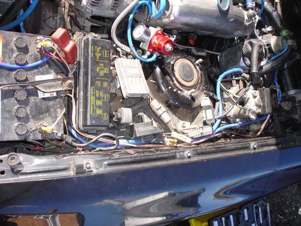
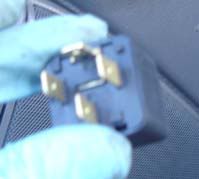
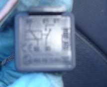
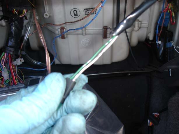
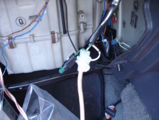
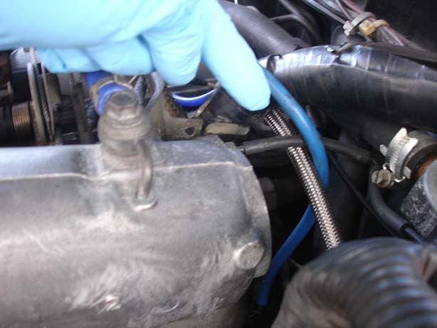
Step 1 - Boost gauge installation. Locate the vacuum hose at the rear of the intake plenum chamber.

p1329344_2.jpg


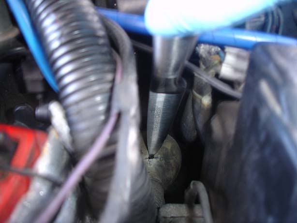
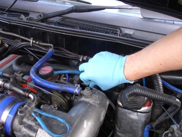
Step 2 - Remove the hose by sliding it straight back towards the rear of the car

p1329344_3.jpg


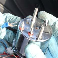
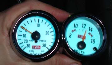
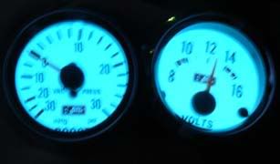
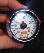
Step 3 - Get yourself a boost gauge, mine was a 30 psi mechanical gauge (mechanical has a feed of air rather than an electronic signal from a sensor), and cost about £15 so nothing too expensive.

p1329344_4.jpg


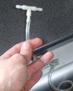
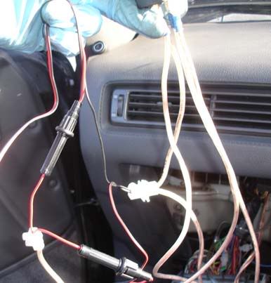
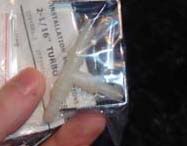
Step 4 - Ensure you have the following (mine came with the gauge)

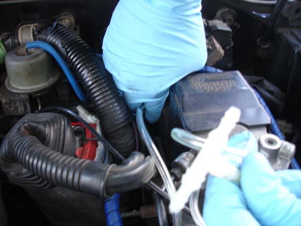
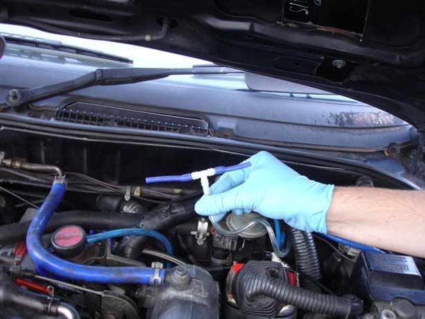
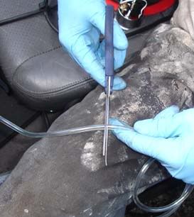
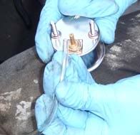
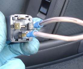
1. T piece to insert another vacuum line into the stock hoses
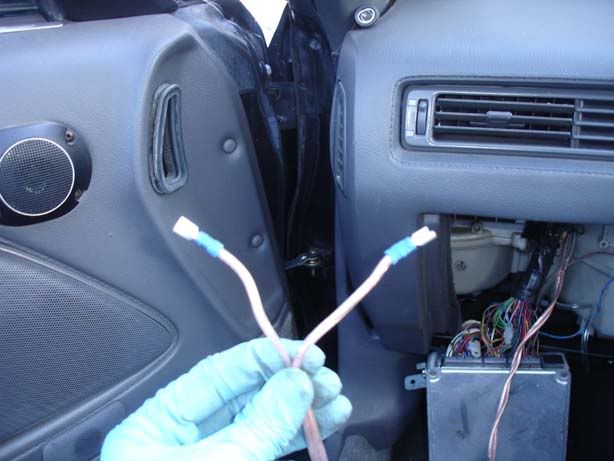
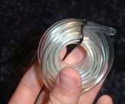
2. A length of vacuum line to run to the gauge
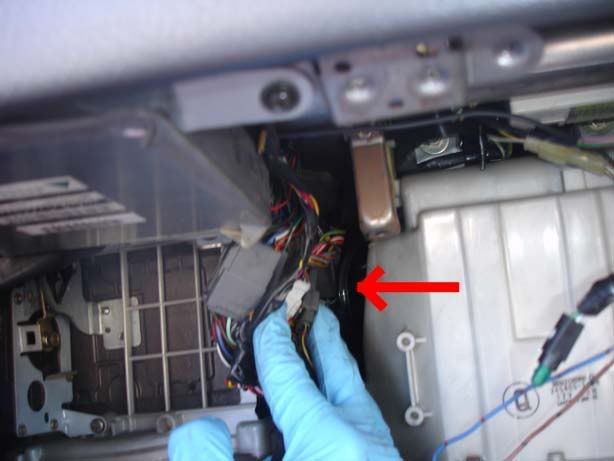
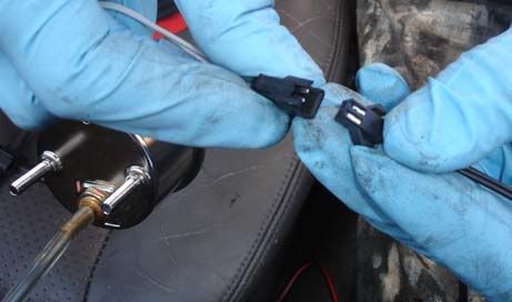
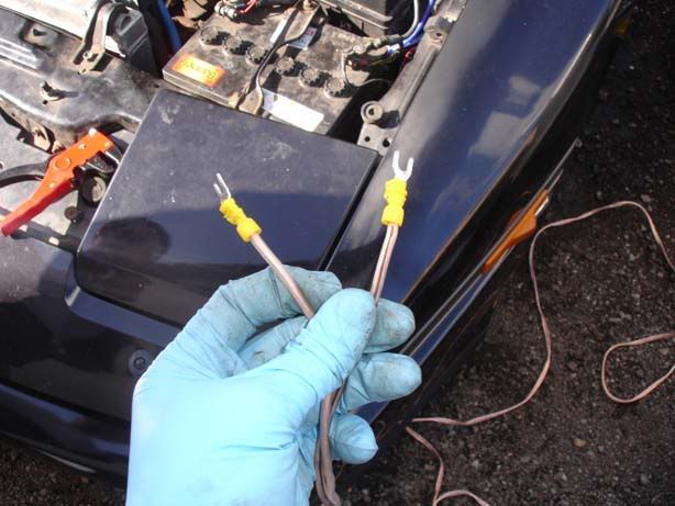
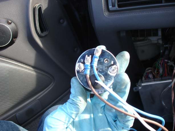
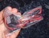
3. Power supply to the gauge (You may find it's just a positive and negative on some)

p1329344_5.jpg

p1329344_6.jpg

p1329344_7.jpg
 

JSeaman

SM Official Expert: Guide Author
SM Expert
May 26, 2009
216
0
0
Derbyshire, UK
Step 5 - Insert the T piece into the hose you will run to the gauge

p1329346_1.jpg


Step 6 - You need to find a place to run this hose line into the car, the easiest route is through the large grommet shown here. This is found at the rear of the engine bay in line with where the glovebox sits inside the car

p1329346_2.jpg


Step 7 - Use a sharp knife to cut a horizontal and vertical line i.e. stab it twice and you have a cross shaped opening that you can push various different sizes of wire through and still keep a reasonable seal

p1329346_3.jpg


Step 8 - Feed the hose into this hole. The easiues way is to push the whole lot through then go hunting around for it inside the car.

p1329346_4.jpg


Step 9 - Remove the glovebox as described in steps 42-48 in the turbo timer guide

Step 10 - If you move some of the connectors aside you should hopefully be able to see the vacuum hose. If not, look for signs of daylight (you may need an assistant to push the split on the grommet for this) and follow that to the hose

p1329346_5.jpg


Step 11 - Retrieve all the vacuum hose so you have minimal slack in the engine bay - you want to leave enough so that you can do whatever routing you require but that won't be more than a few inches of hose.

p1329346_6.jpg


Step 12 - Cut two lengths of hose and fit them to the T piece (Note you can cut the stock hose you removed in half and use this). Note the second picture shows that I was a little over zealous and hads to trim down one side to prevent a kink appearing in the silicone

p1329346_7.jpg

p1329346_8.jpg


Step 13 - Fit the T piece in place of the stock hose

p1329346_9.jpg


Step 14 - Trim the vac hose in the car to make sure you have just enough to hook the gauge up. Don't cut it so short you have no slack but try to keep vac/boost line runs to a minimum

p1329346_10.jpg


Step 15 - Fit the hose onto the back of your boost gauge

p1329346_11.jpg


Step 16 - If your gauge is anything like mine then it has a power supply with a little potted box of electronics, now is the time to plug this in so you end up with 2 wires, positive and negative

p1329346_12.jpg


Step 17 - As mentioned earlier, I'm going to run at least 5 gauges and probably some other bits and bobs so I wanted a decent power source. I ddi this using a relay and a feed from the battery. This might be overkill for some of you but certainly won't hurt and will only cost a few quid so I've included how I did it.

First, get a length of cable (about 2M) with 2 cores/sets of wires and put on some connectors for the battery - ensure this cable is large enough to carry current for your needs, gauges only require a few hundred mA (milliamps) so any reaosnable cable will do. Ring connectors would have been better but I had these ones lying around.

p1329346_13.jpg


Step 18 - Run the cable through just like you did with the boost hose

p1329346_14.jpg


Step 19 - Try and tuck the cable away or cover it in sheath etc so it doesn't stand out too much or get in the way of any moving parts

p1329346_15.jpg


Step 20 - Terminate the other end with a couple of female spade clips (these will go onto your relay)

p1329346_16.jpg
 

JSeaman

SM Official Expert: Guide Author
SM Expert
May 26, 2009
216
0
0
Derbyshire, UK
Step 21 - Grab yourself a 4 pin relay which looks like this:

Notice the circuit diagram on the top which is supposed to help you wire it!

Basically you have a ground connection (one of the wires we just connected to the battery), a positive feed (the other battery connection), an output (that will supply all our gauges) and an input (that will switch the relay on)

The relay means we can use a very small current draw off an existing wire in the car to switch in all our gauges etc from a direct source of the battery

p1329347_1.jpg

p1329347_2.jpg


Step 22 - Hook up the positive and negative supply

p1329347_3.jpg


Step 23 - Now you need a source to turn the relay on, I wanted the gauges to come on with the lights to I picked the easiest route and stole a feed from the glovebox light. This light is not always on when the lights are switched on but that is due to the switch (on the right hand side of the glove box) cutting off the ground connection so this is powered constantly when the lights are on. You may choose an alternative e.g. the back of the head unit for your stereo

p1329347_4.jpg


Step 24 - I couldn't be bothered to get the heat shrink and soldering iron out but splice in a connection that you can run to the relay as well as retaining the stock light - I just threw in a block connector

p1329347_5.jpg


Step 25 - Once you have positive, negative and the switched supply you just simply attach the positive wire of your gauges to the relay output. I did two things here

1. Cut the ground wire from the battery to the relay and inserted another block connector inline - this means I can just add another wire to the block connector to groun another piece of equipment

2. Fitted the final wire to the relay which is the output to the gauges. This one terminated in a block connector thaty would then allow me to add the power wires to each gauge.

So we're left with a couple of block connectors to hook up the gauges

The picture shows

a) The two red wires with inline fuses (the black plastic things) are hooked up to the power connector mentioned in '2' above

b) The negative supply to the gauges (black wire) go to the other block connector which has the ground wire to the battery/relay joined in one side of it

c) The relay is being held at the top with all 4 connections

p1329347_6.jpg


Step 26 - Add more gauges if you desire. I'll walk through the volts gauge because it is an electrical connection rather than mechanical. First, get a voltage gauge - cheap one is fine for this, mine was about £10 ish. I am using voltage because I intend to have an elaborate twin alternator/battery set up going at some point but it's always useful to know how your battery/alternator is

p1329347_7.jpg


Step 27 - The back of the gauge has two terminals with nuts on them. One is marked I (for ignition) and the other G (for ground). Simply run a connector (such as our battery feed) to the gauge and bolt it one. You should end up with something like that shown in picture 2

Note : If you run a permanent feed then the gauge will be on (and therefore draing current) all the time. This is no big deal if you use the car daily but if it's likely to stand for long periods then make sure you pick a switched live

p1329347_8.jpg

p1329347_9.jpg


That's it really, nothing to it. Here are mine when switched on (second one with no flash shows the colour better but blurred) :

p1329347_10.jpg

p1329347_11.jpg