GUIDE : Fitting a turbo timer

JSeaman

SM Official Expert: Guide Author
SM Expert
May 26, 2009
216
0
0
Derbyshire, UK
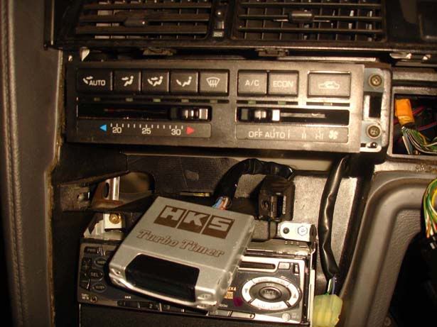
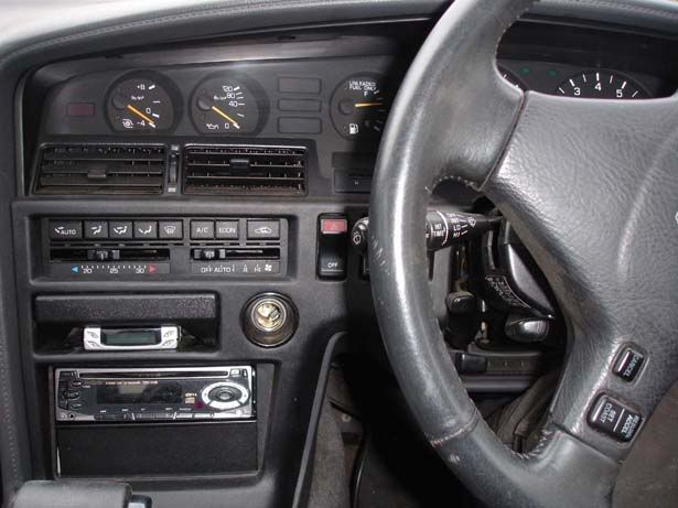
This guide will walk you through the installation of an HKS type 1 turbo timer (In the ash tray). A lot of the information should be useful for any brand of turbo timer as much of the task will be the same. I highly recommend you get a fitting kit with it as it saves a lot of hacking into looms which can be messy.

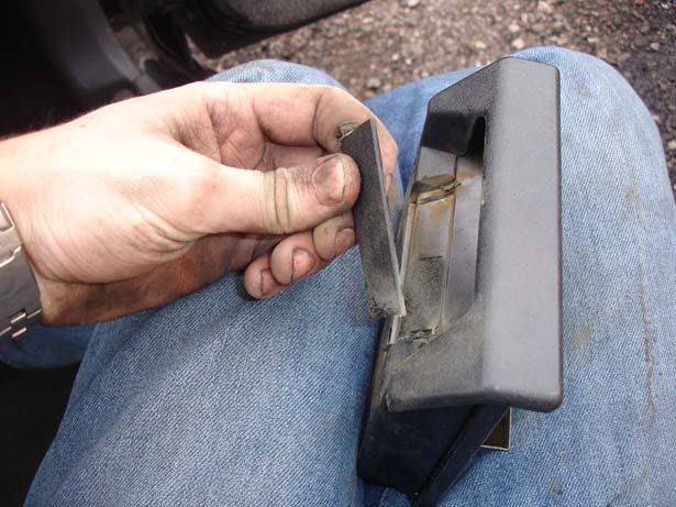
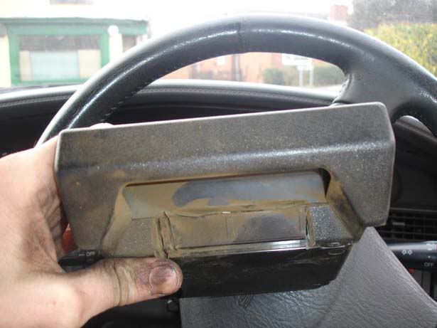
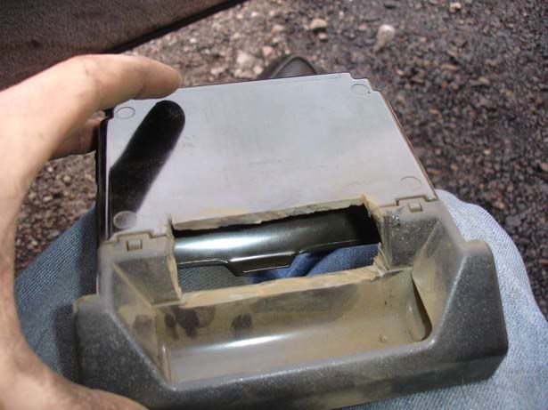
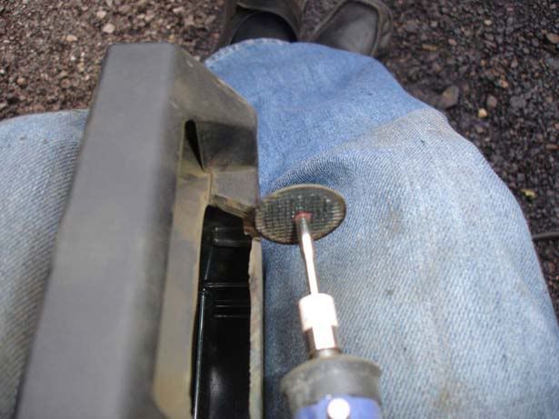
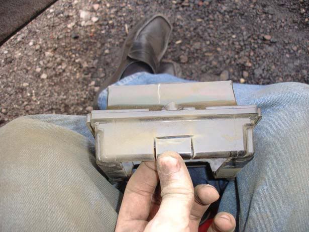
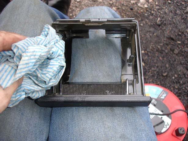
Note that installing it where the ash tray goes means cutting up the plastic of the ash tray which is some seriously nasty stuff to be breathing in. Well ventilated area and/or a mask would be well worth using for this. Oh, and you don't have to be a genius when it comes to working with plastic - even if you do quite rough cuts they won't get seen because the timer sits proud of any hacking you do!

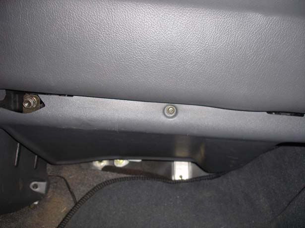
Step 1 - Remove the two screws shown under the sterring columns

p1329244_1.jpg


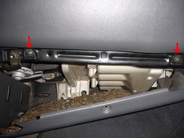
Step 2 - Remove two screws on the other side of the panel

p1329244_2.jpg


Step 3 - Pull the bonnet release mechanism forward to reveal two further screws you must remove

p1329244_3.jpg


Step 4 - I found it easier to have access by removing this panel. It simply pulls off

p1329244_4.jpg


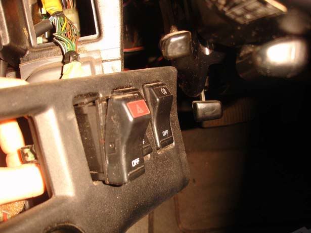
Step 5 - Remove the cover for the steering column by sliding it down towards the pedals. There are tabs along the top (See picture) so you should be careful not to stress anything by pulilng hard/in the wrong direction

p1329244_5.jpg


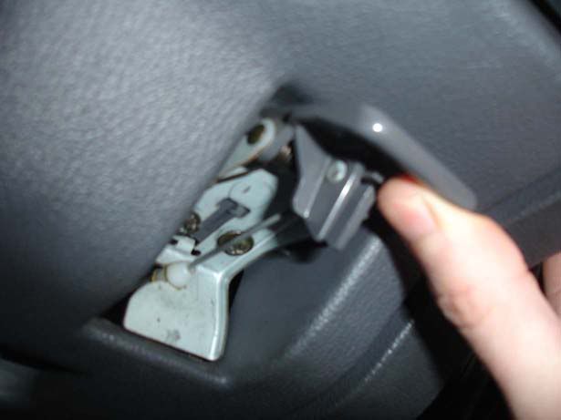
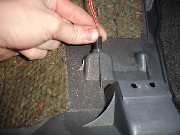
Step 6 - Now you can see the inside of the trim you will be able to remove the bonnet pull by sliding it out after lifting the clip shown in the picture

p1329244_6.jpg


Step 7 - The last thing to do with this trim is remove the light that is housed in the plastic by twisting it and then pulling it clear

p1329244_7.jpg


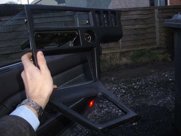
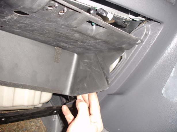
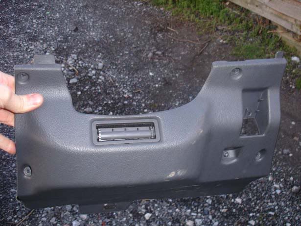
Step 8 - Remove the trim from the car

p1329244_8.jpg


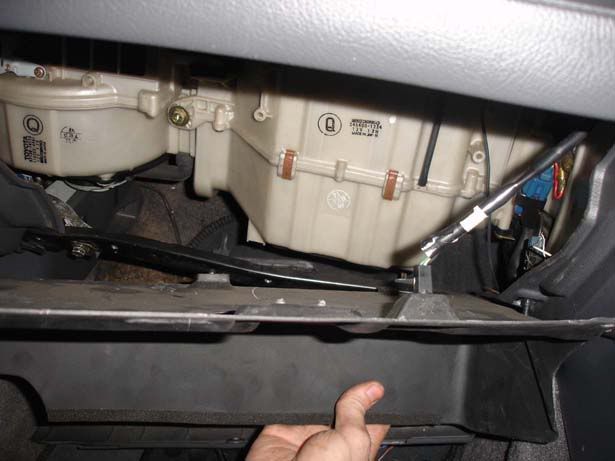
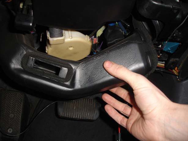
Step 9 - Remove the air ducting by pulling down the right hand side (Picture 1) then easing the left hand side out (Picture 2). There are no clips or screws, simply an interference fit with a foam seal

p1329244_9.jpg

p1329244_10.jpg


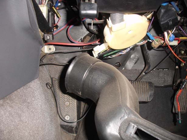
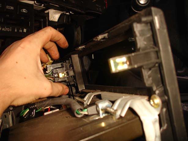
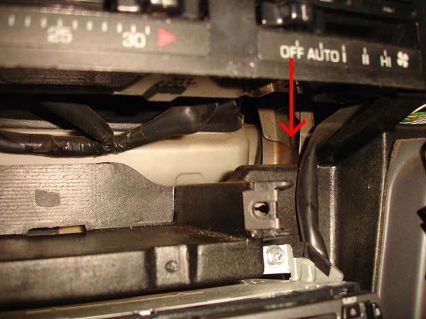
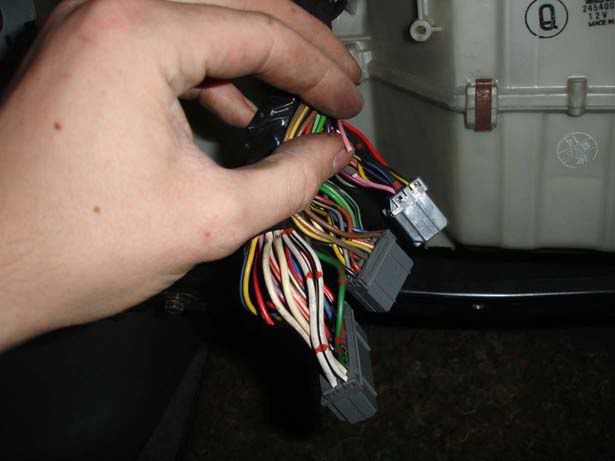
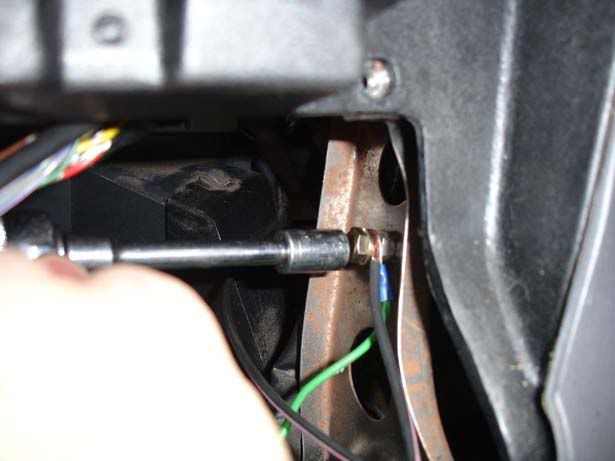
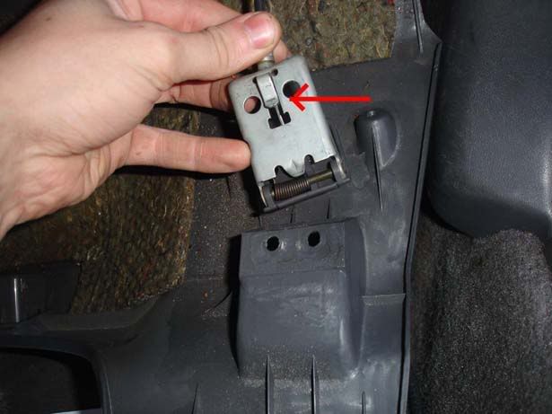
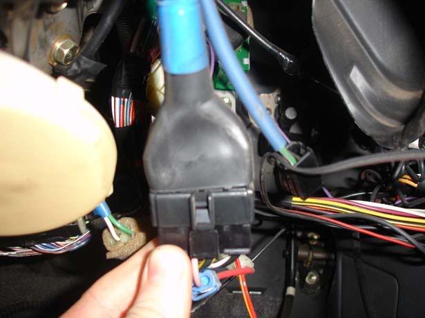
Step 10 - Locate this large connector for the ignition

p1329244_11.jpg


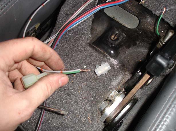
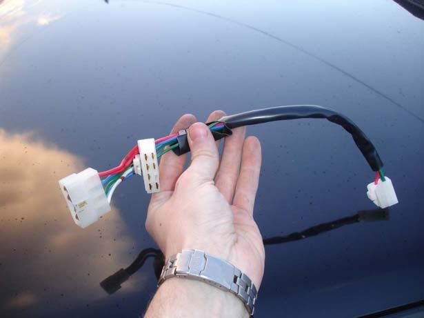
Step 11 - Hopefully you will have bought a fitting kit which looks like this. You can see that it will be inserted as a pass-through for the connector shown in step 10 and also produce a flying lead for the turbo timer itself

p1329244_12.jpg


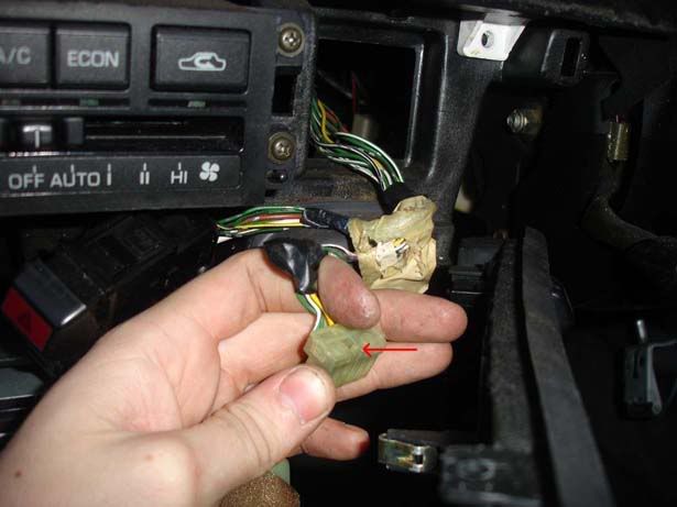
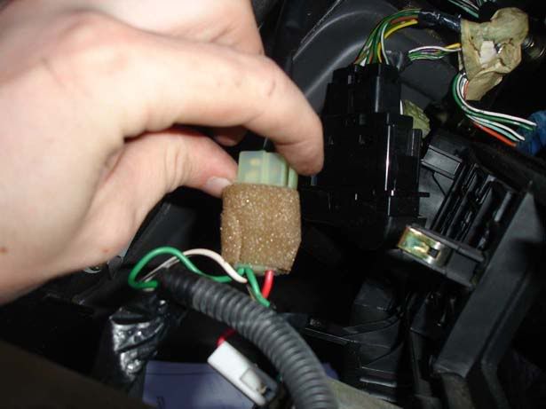
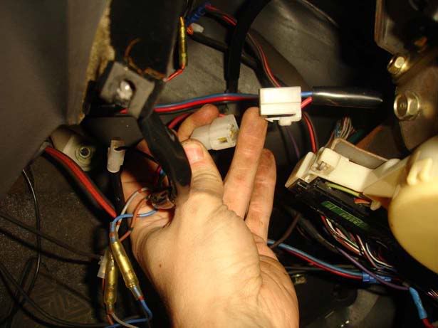
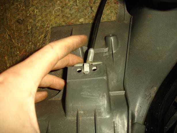
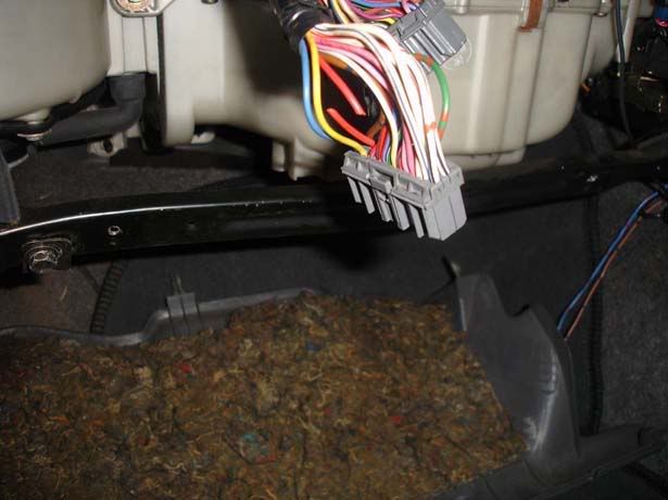
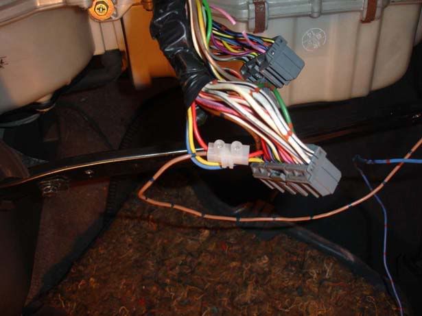
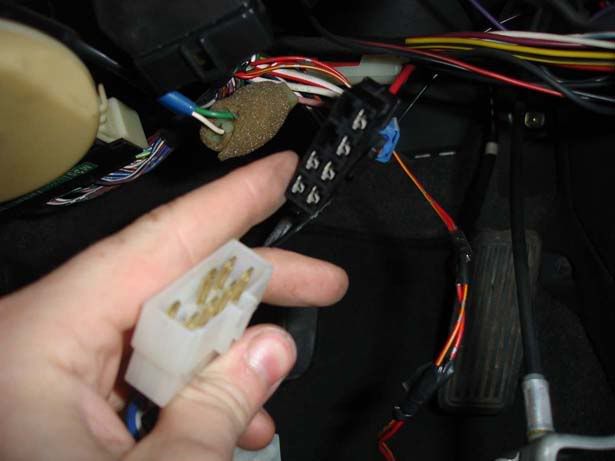
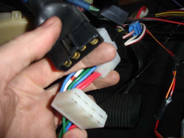
Step 12 - Press the locking tab on the connector (From step 10) and separate it. Insert the turbo timer's harness in between

p1329244_13.jpg

p1329244_14.jpg


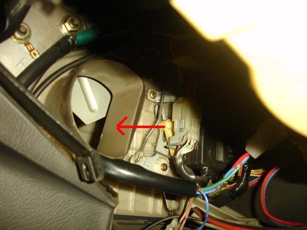
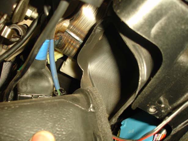
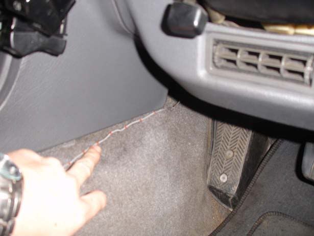
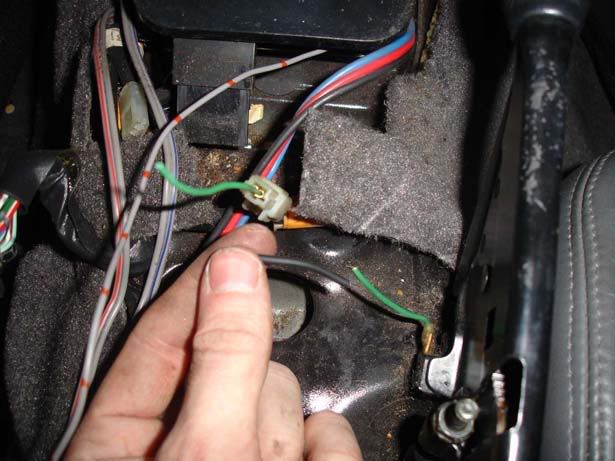
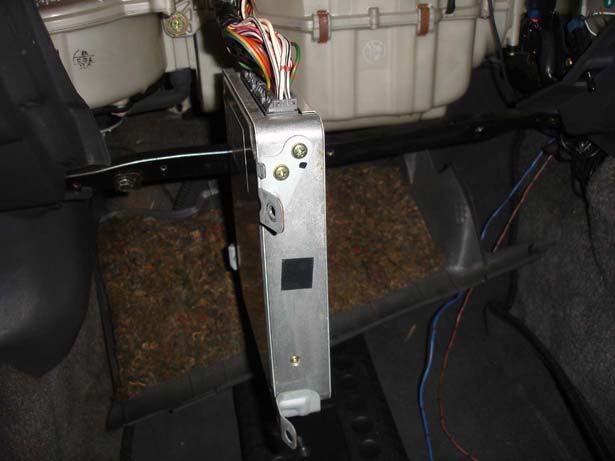
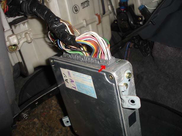
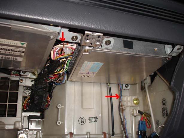
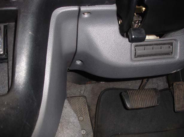
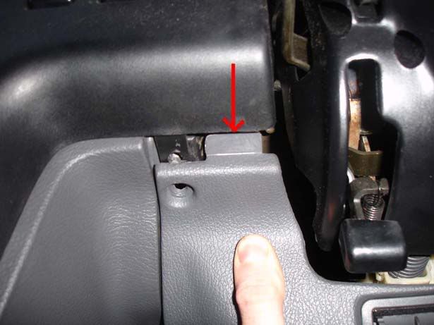
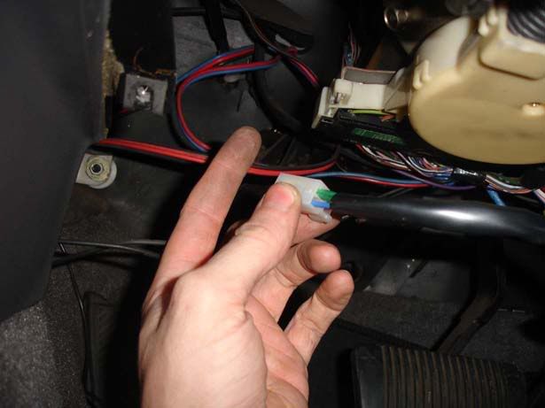
Step 13 - You now need to route the flying lead over the steering column and it should come out where my finger is pointing in the picture

p1329244_15.jpg


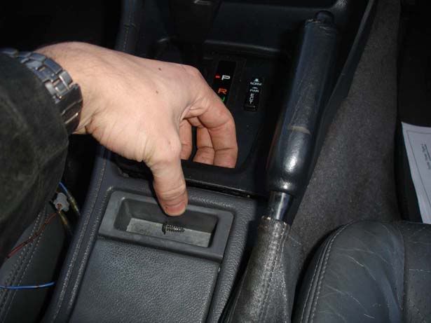
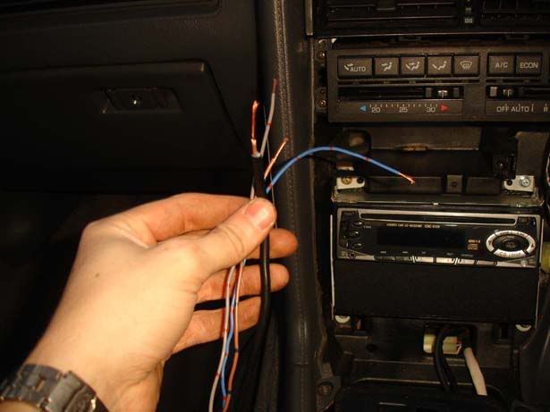
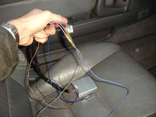
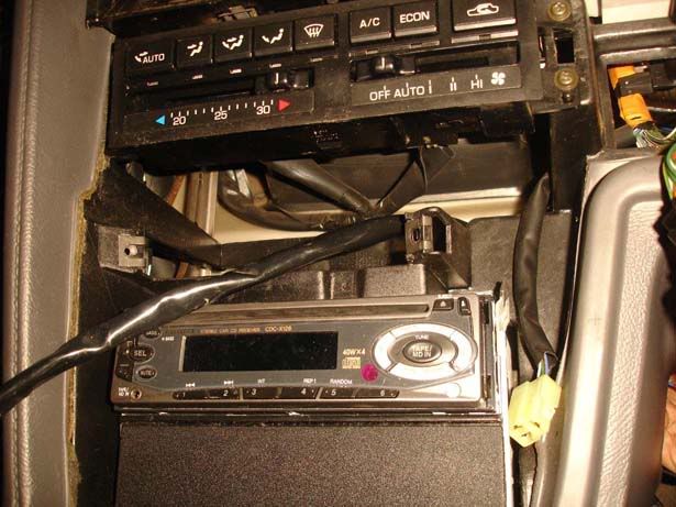
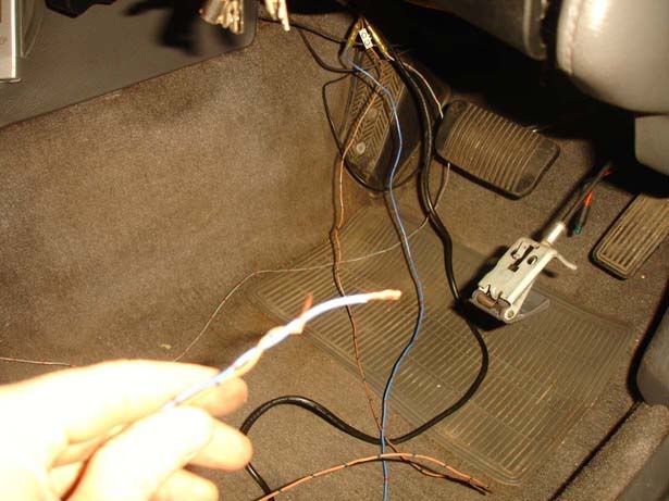
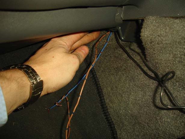
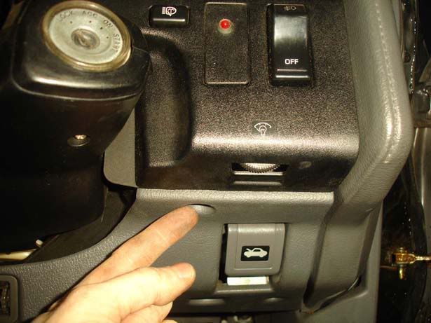
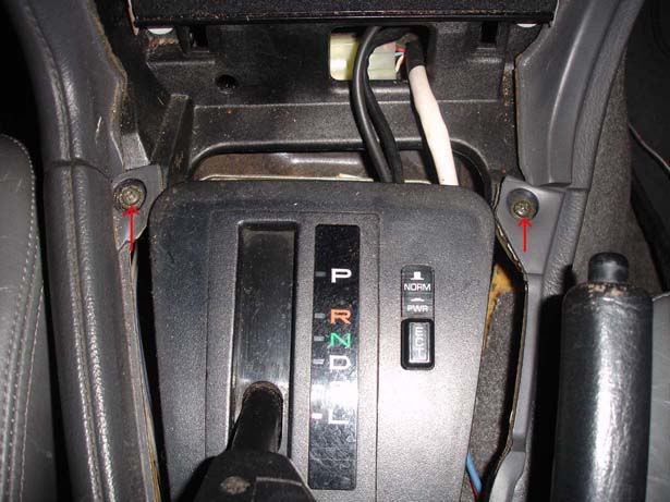
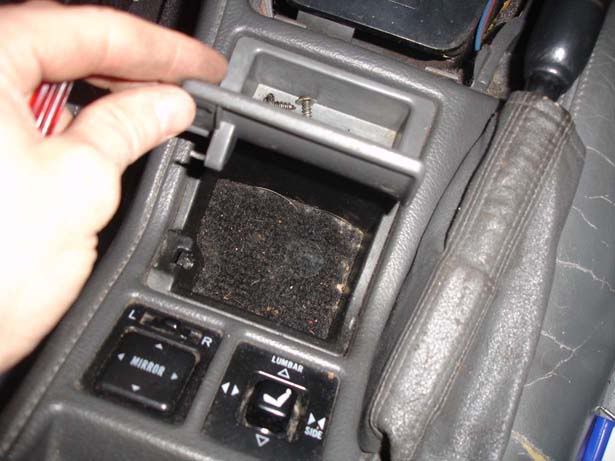
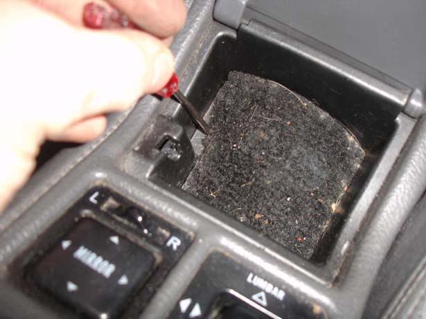
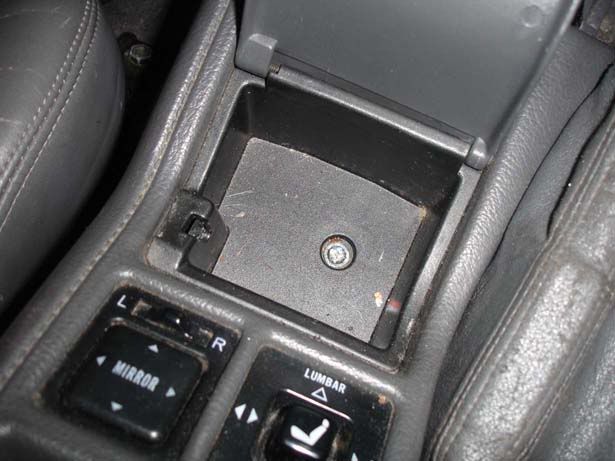
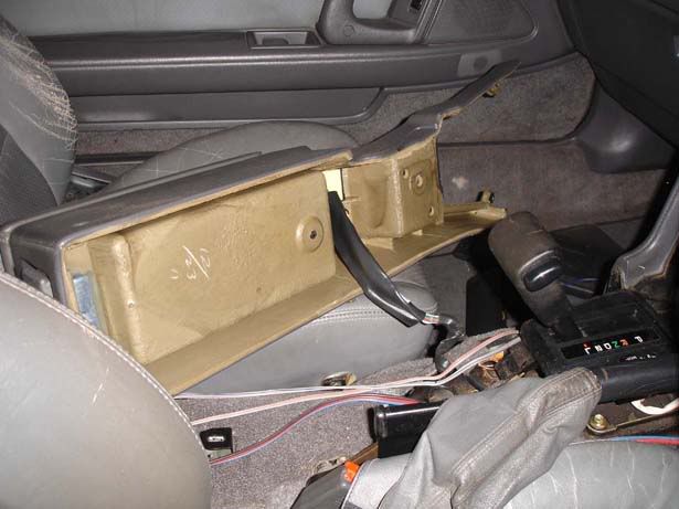
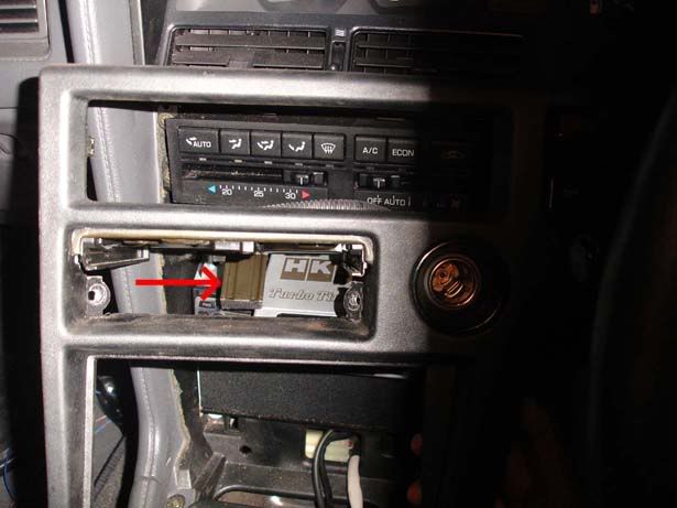
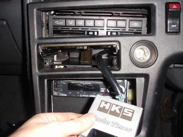
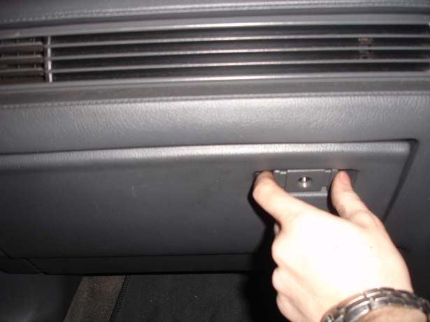
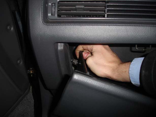
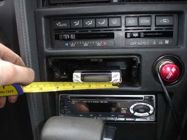
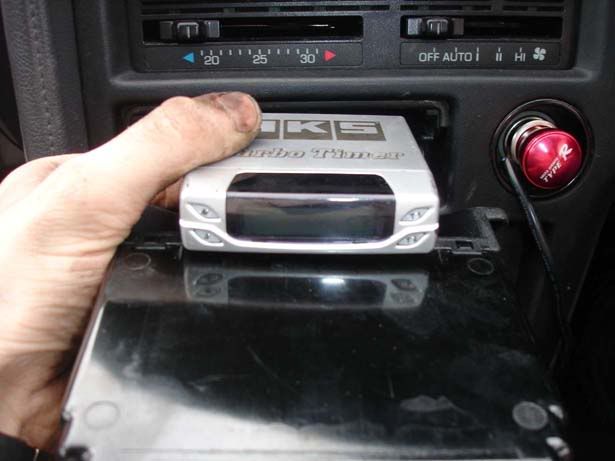
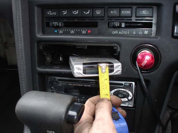
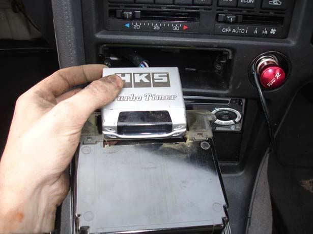
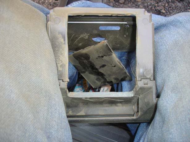
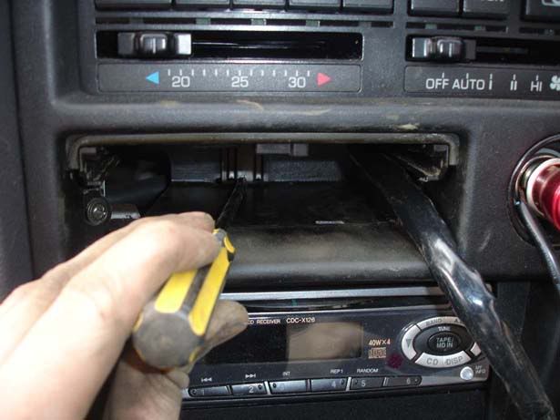
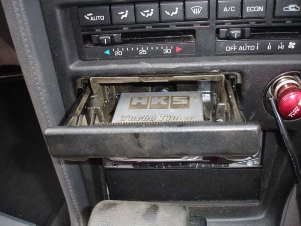
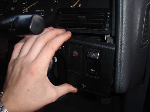
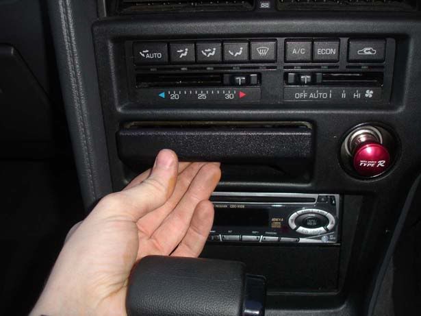
Step 14 - Now you have wired into the ignition, you need to route the wires to the ECU and install the timer itself. We move to the centre of the car now and start by removing the ash tray. The second picture shows you the tab you press to pull the ash tray completely out

p1329244_16.jpg

p1329244_17.jpg


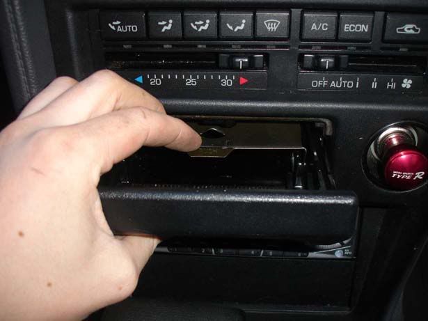
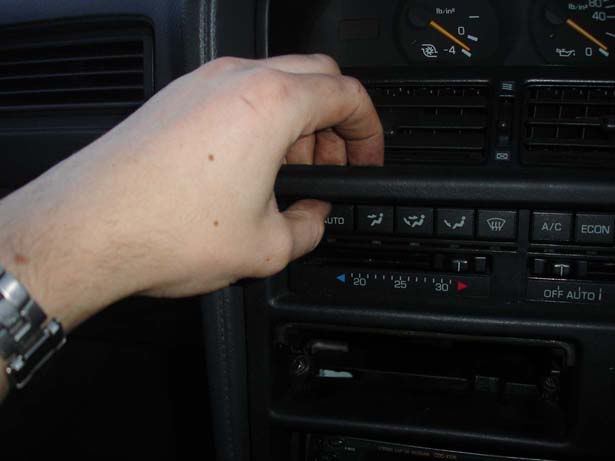
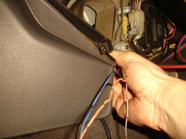
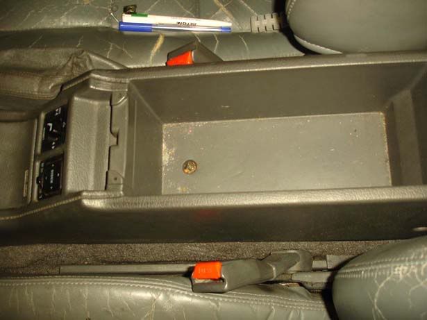
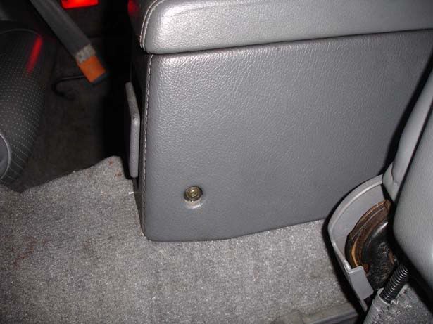
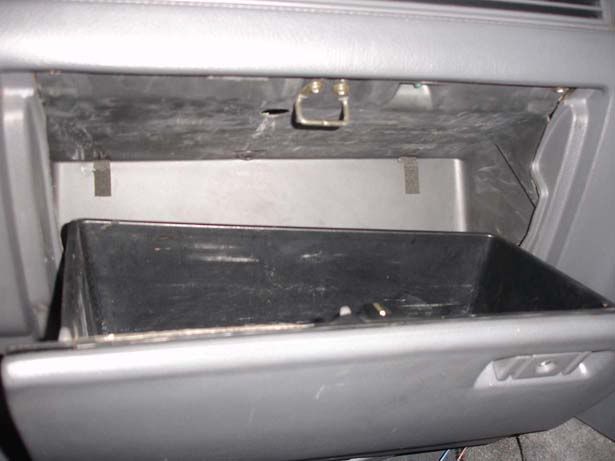
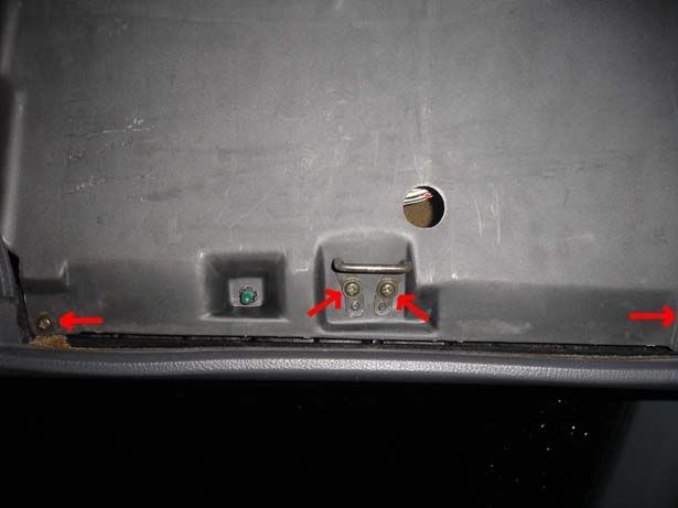
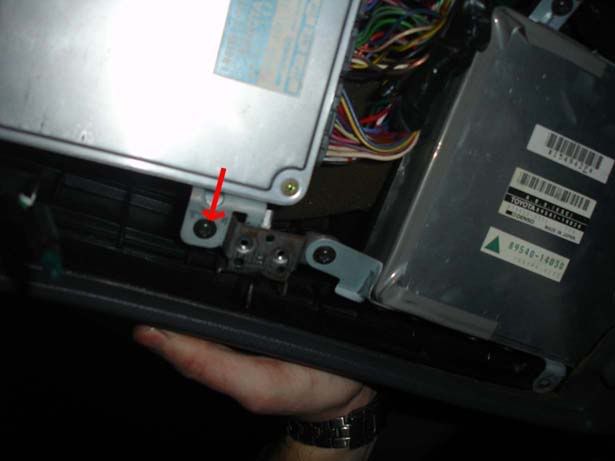
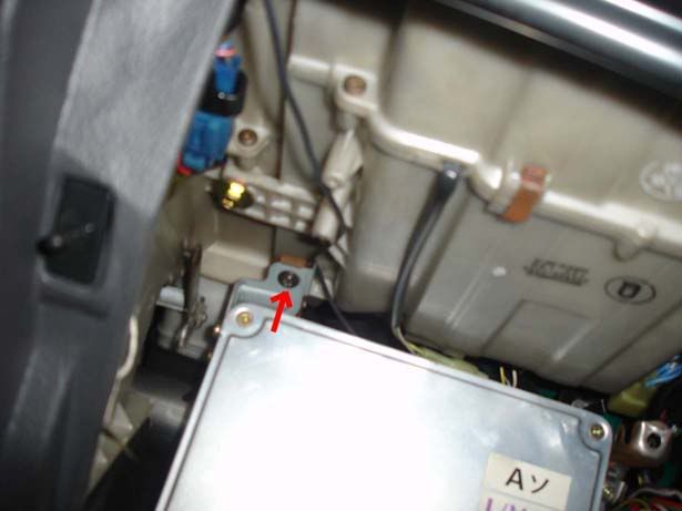
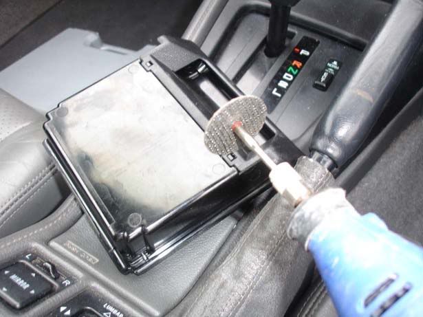
Step 15 - With the ash tray removed you should see two screws (I only had one), remove these

p1329244_18.jpg


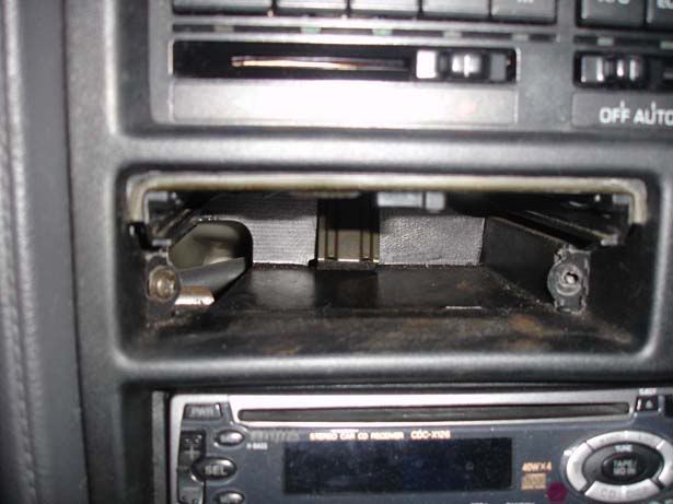
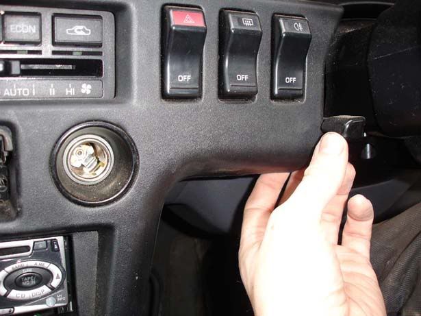
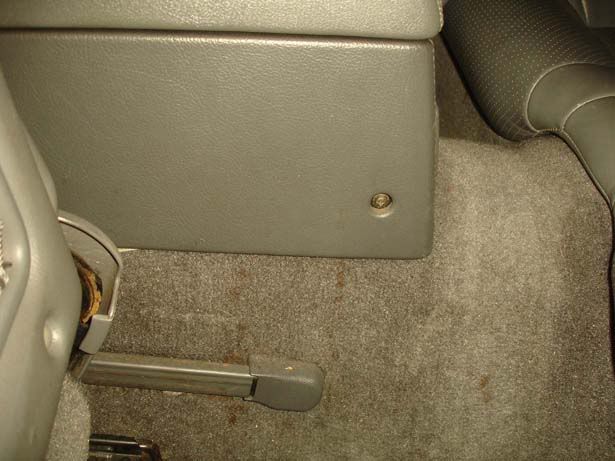
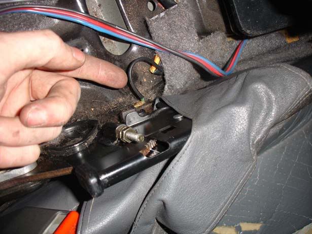
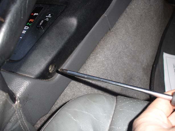
Step 16 - Remove the screw by the gearstick on the driver's side

p1329244_19.jpg
 

JSeaman

SM Official Expert: Guide Author
SM Expert
May 26, 2009
216
0
0
Derbyshire, UK
Step 17 - Free the surround by pulling in the places shown in the 3 pictures

p1329249_1.jpg

p1329249_2.jpg

p1329249_3.jpg


Step 18 - For a manual, put your gearstick in 4th, for an auto go for L - this helps slide the piece out. Drop the hand brake too and ease the surround out past the steering wheel adjuster. Note you can't remove it completely just yet because there are still bits attached

p1329249_4.jpg


Step 19 - You can simply take the 3 connectors off for hazards, fogs and rear screen or you can pop the buttons out and by squeezing the top and bottom (Picture 1) and they will slide forward (Picture 2). I did this because I wasn't sure I'd have time to complete the install and I wanted to be able to indicate (You can't without the hazard switch in), if I had to abandon it half way through.

The third picture shows the little tab which you push to release the connectors (They all have one so don't just pull them)

p1329249_5.jpg

p1329249_6.jpg

p1329249_7.jpg


Step 20 - Remove the cigarrete lighter wiring by squeezing the connector and sliding the two ends apart

p1329249_8.jpg


Step 21 - Remove the surround completely

p1329249_9.jpg


Step 22 - Look in the ash tray hole and you should be able to see a path for the wiring to go

p1329249_10.jpg


Step 23 - On the HKS unit you should have a grey wire (hand brake), blue wire (Speed), brown wire (RPM) and a ground wire (Probably not as big as the one I've got).

p1329249_11.jpg

p1329249_12.jpg


Step 24 - If you haven't done much in car wiring before then the trick for situations like this is to feed the wire in with one hand (Picture 1) and grab the other end with the other hand (Picture 2 - this is looking from under the steering column towards the centre of the car). I ignore the wires and try and make my fingers touch and then you can pass the wires through, bit fiddly this bit

p1329249_13.jpg

p1329249_14.jpg


Step 25 - Take up the slack but leave enough so you can move the turbo timer around a little. Ths picture shows how much I left

p1329249_15.jpg


Step 26 - You should now be able to plug the turbo timer connector into the flying lead you routed over the steering column

p1329249_16.jpg


Step 27 - Another fiddly bit, you need to route the blue and brown (speed and RPM respectively) wires to the ECU which means pushing the wires all the way through to the other side of the car. I found twisting the wires as shown in the pic then pushing them from the driver's side all the way was best. Then you go to the passenger side and route around until you find them!

All being well they should come out the other side like mine in picture 2

p1329249_17.jpg

p1329249_18.jpg


Step 28 - Insert the ventilation pipework back in the side nearest the centre of the car first (picture 1). Then offer the other side up to the plastic mould and wiggle it from left to right to seat it correctly

p1329249_19.jpg

p1329249_20.jpg
 

JSeaman

SM Official Expert: Guide Author
SM Expert
May 26, 2009
216
0
0
Derbyshire, UK
Step 29 - Get the trim for under the steering column and insert the bonnet release mechanism (Slides in) and twist the light back in

p1329250_1.jpg


Step 30 - Put the four screws you removed earlier back in. Note : If you removed the trim holding the alarm/headlight washer/fog light then you'll need to put this back before you do the screw up for the trim

p1329250_2.jpg


Step 31 - Time to route the hand brake (grey) wire now. This should be loose dangling around the footwell on the driver's side. Open your centre console lid and undo the screw at the bottom of it

p1329250_3.jpg


Step 32 - Pull the passenger seat forward and undo the screw at the rear of the storage compartment. Do the same on the driver's side (picture 2)

p1329250_4.jpg

p1329250_5.jpg


Step 33 - Remove the two screws holding the front of the centre console in

p1329250_6.jpg


Step 34 - Pop the coin storage compartment open and use a small flatblade screwdriver to remove the felt bottom

p1329250_7.jpg

p1329250_8.jpg


Step 35 - Remove the screw you find underneath the fabric

p1329250_9.jpg


Step 36 - Slide the centre console towards the rear of the car then turn it over onto the passenger seat. Note you still have some wiring attached for the mirrors and seat

p1329250_10.jpg


Step 37 - Locate the hand brake wire as shown. This is what makes your handbrake warning light come on.

p1329250_11.jpg


Step 38 - Run the grey handbrake wire up under the plastic trim around the centre console - you should be able to just push this up with your finger, it won't fall out again

p1329250_12.jpg


Step 39 - Remove the black sheath around the cable, cut the wire in half and rejoined it with your grey turbo timer wire (Then replace the sheath)

p1329250_13.jpg

p1329250_14.jpg


Step 40 - Refit the centre console by doing steps 36-32 in reverse

Step 41 - Refit the black surround. Note that the ash tray compartment has a piece of metal at the back, be careful not to hit the turbo timer with this. Second picture shows the turbo timer avoiding the piece - note how much slack there is on the turbo timer, you don't want it too tight because it makes the job a lot harder

p1329250_15.jpg

p1329250_16.jpg


Step 42 - Now we move over to the nearside to connect to the ECU. Leave the glove box shut at first, Undo the single screw at the centre of the base of the glove box. This will drop down a piece of trim to gain access to the hinges

p1329250_17.jpg


Step 43 - Undo the two screws holding the hinges on

p1329250_18.jpg


Step 44 - Now go to open the glove box whilst supporting it at the base and it should drop down (Second pic) but it won't come out yet

p1329250_19.jpg

p1329250_20.jpg
 

JSeaman

SM Official Expert: Guide Author
SM Expert
May 26, 2009
216
0
0
Derbyshire, UK
Step 45 - Lifting the left hand side up with the right hand side lowered you should be able to hook the glovebox out of position

p1329251_1.jpg


Step 46 - Looking up at the underside of where the glovebox sits you should see four screws (Three are on the picture and one is just out of the shot). Two are for the hinge and one in each corner - undo all of these

p1329251_2.jpg


Step 47 - Now the glovebox can be eased away from the side nearest the centre console

p1329251_3.jpg


Step 48 - Note that there is still a bulb attached which is another twist fit, remove this then pull the cover clear

p1329251_4.jpg


Step 49 - You can now see the ABS box and the ECU (Both are labeled). There are two screws holding the ECU in place, undo them both

p1329251_5.jpg

p1329251_6.jpg


Step 50 - Now the ECU should be able to drop down so you can get access to the connectors

p1329251_7.jpg


Step 51 - Remove the 3 connectors by insrting a flatblade screwdriver under one of the recesses shown, pushing in the locking tab (The plastic flap in the middle of each connector) then gently pry it upwards.

p1329251_8.jpg

p1329251_9.jpg


Step 52 - Now you go to the TSRM and identify wires. You need IGA or IGT for the RPM wire (brown) and SPD for the speed wire (blue). Splice them in to the wiring. Picture is of one of the ECU wires cut - you can see it's a bit fiddly because you haven't got much slack

p1329251_10.jpg


Step 53 - Here's a picture of my block connector joining the wire. I recommend you strip and solder the wires and wrap in heatshrink if you have the resources.

p1329251_11.jpg


Step 54 - Cable tie the blue and brown wires together and run them up to the ECU as shown

p1329251_12.jpg


Step 55 - Pop the glove box stuff back in (This really is the opposite of removal, nothing tricky here)

Step 56 - Measure the turbo timer width so you know how much to cut out the ash tray

p1329251_13.jpg


Step 57 - Make markings on the ash tray based on your measurements then check with the turbo timer itself to see that they look correct (This is where slack helps again in the wiring)

p1329251_14.jpg
 

JSeaman

SM Official Expert: Guide Author
SM Expert
May 26, 2009
216
0
0
Derbyshire, UK
Step 58 - Use a dremel to cut out the markings (This is only a guide cut so make it quite shallow, you don't want to cut too far). I always cut it smaller than the size I need deliberately, that way any mistakes can easily be corrected. It goes without saying that it's easier to grind off a bit of plastic than try and build it back up again so I highly recommend you do the same

p1329253_1.jpg


Step 59 - The ash tray has two layers of plastic at the front so cut away the first one as shown in the picture before moving on to the second piece

p1329253_2.jpg


Step 60 - Once you've got your two small vertical edges you need to measure the height of the turbo timer for your horizontal cut

p1329253_3.jpg


Step 61 - Do the long cut across the top, again I advise you cut short and grind it back to fit

p1329253_4.jpg


Step 62 - Cut a line along the bottom of the timer and also extend your vertical cuts to meet the horizontal one so you can pull away a section of plastic and test fit the timer (second picture)

p1329253_5.jpg

p1329253_6.jpg


Step 63 - Start grinding it back until you have a snug fit around the turbo timer. You don't want the device sliding around but you also don't want to scratch it to bits when you fit the thing in the ash tray so just take small amounts off the ash tray until it sits firmly in place

p1329253_7.jpg


Step 64 - Once you have the correct dimensions, extend your cut along the base of the ash tray so the whole turbo timer body will sit in it

p1329253_8.jpg


Step 65 - Cut out a square at the back of the ash tray for the wiring to go through (Make this too big rather than too small seeing as it will never get seen)

p1329253_9.jpg


Step 66 - I removed the backing of the ash tray completely by hitting a screwdriver into it with the base of my hand. I also bent back the metal piece shown in the picture. This helps to get the wiring in without deforming it

p1329253_10.jpg


Step 67 - With that all done, the turbo timer should sit in place and allow the ash tray to close

p1329253_11.jpg


Step 68 - Take the ash tray out and give everything a wipe with a damp cloth to get rid of the (seriously evil!) dust from the plastic you've been cutting

p1329253_12.jpg


Step 69 - Insert the turbo timer for the final time in your newly cleaned ash tray

p1329253_13.jpg


Step 70 - Close it, test it, admire the good job you've done!

p1329253_14.jpg

p1329253_15.jpg


Note : I didn't show the wiring of the black wire from the turbo timer to ground because I ran short on time. All you need to do is take the wire and connect it to the chassis or any ground point/wire already in the car. There are loads of them including most nuts and bolts you can see bare metal on. It's easiest if you stick an O-shaped connector on the wire and then screw/bolt it down to the chassis - I bolted mine to the inside of the stereo cage as shown in the following picture

p1329253_16.jpg