
This thread is intended to answer basic questions about the lighting set-up in the MKIII. I have completed the gauge lighting and climate control using LED's and a PWM dimmer. The first two posts will be continually updated as I complete all my lighting throughout the car.
Gauge Cluster Lighting
FROM THIS:
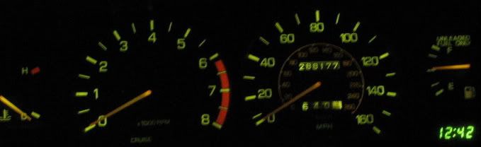
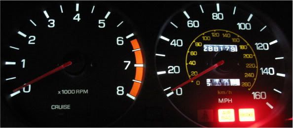
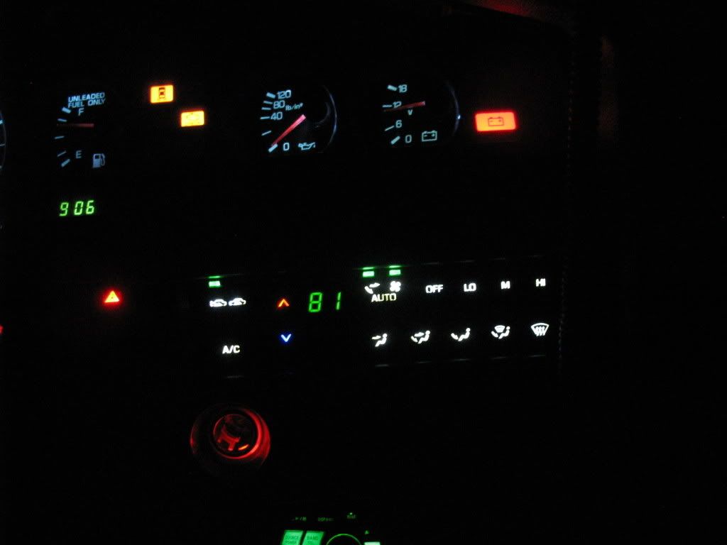
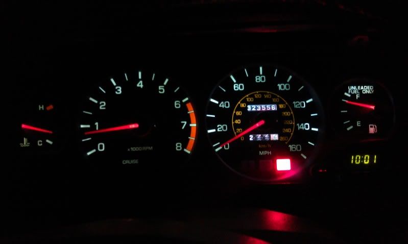
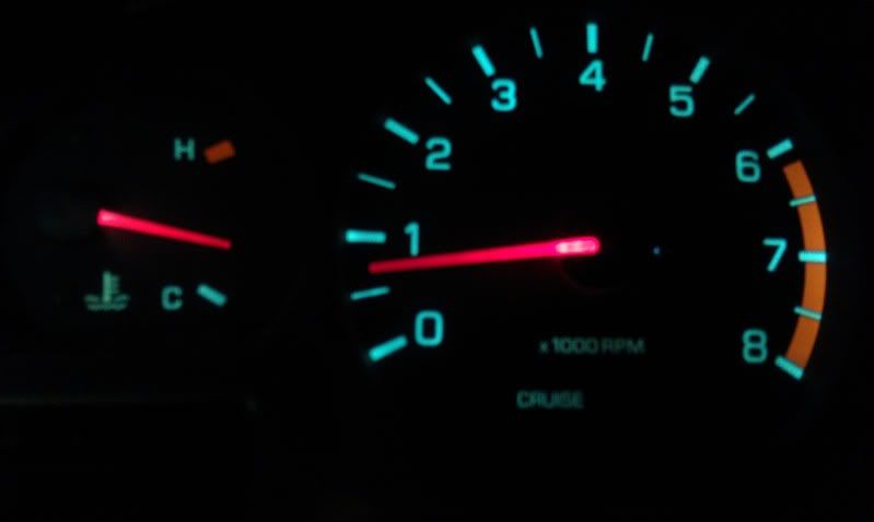
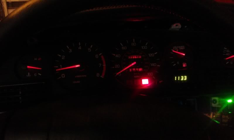
TO THIS:
Bulbs:
Type_____Qty
#194_____4
#74______1
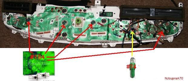
Many members have used LED's from with success. These LED's are simply "plug and play" and require no extra modification.


_____194__________74______
Simply remove the old bulb and replace with a new LED bulb.
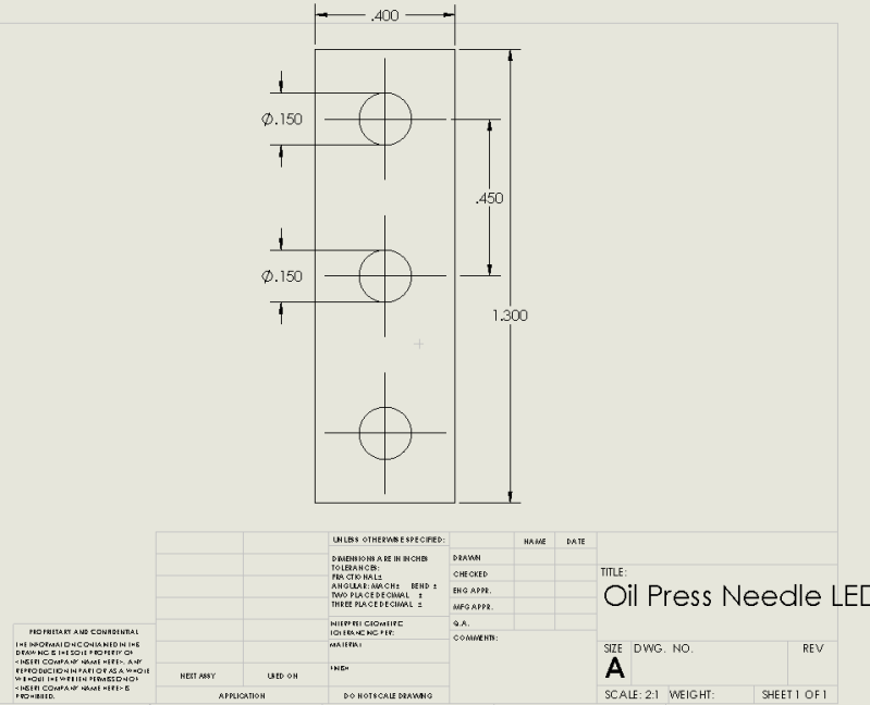
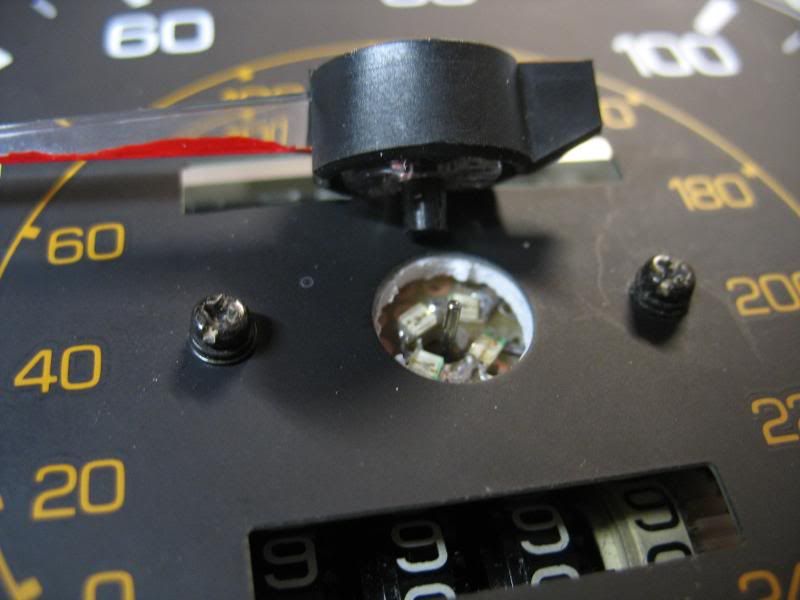
When using the 5 WLED bulbs the oil gauge may appear dimmer than the other gauges since the oil gauge is lit by only one #74. I solved this COMPLETELY by placing a small section of aluminum foil over the bulb, directing most all the light onto the gauge face and its clear plastic "light carrier".
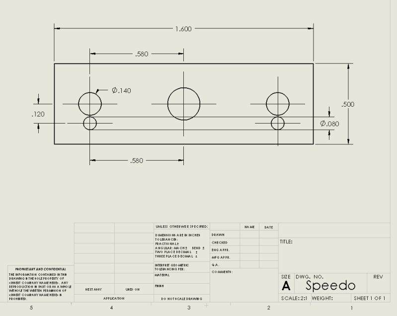
Light dispersion is very important for the gauge cluster's appearance. "Hot spots", where lights can become focused, are your enemy. When using LED lights, hot spots can be a problem. This can be fixed by using "wide angle" LED lights. These lights put more light out the sides of the bulb and help to prevent hot spots. Using the 5 bulb LED's from superbrightled can lead to hotspots directly in front of the bulbs. (3 and 9 O'clock on the speedo and tach especially) I solved this by painting the tip of the top bulb black. Using just these bulbs will tend to make any painted needle appear dimmer. Beware.
Another method is to paint the incandescent bulbs. This is a cheap and relatively easy way to change the color, but care must be taken not to overcoat the bulbs making them too dim.
Climate Control Unit
Bulbs
29 - T1 (3mm)
13 for the indicators
16 for the buttons
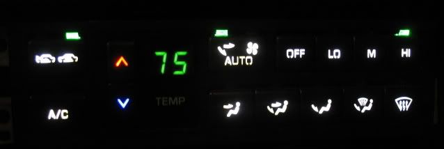
Using the 3mm LED's from superbright made my climate control insanely bright. If I were to do this again, I would use an LED with a lesser MCD rating. Mine were rated at ~4500 mcd and that was way too much. Looks neat by itself, but it is blinding at night on a highway.
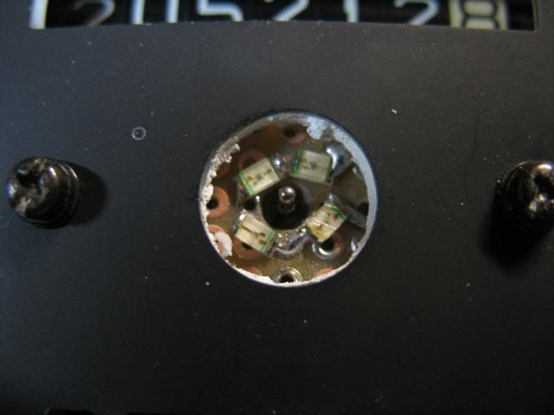
CC unit disassembled, showing the Temp display and the button lighting LED's:

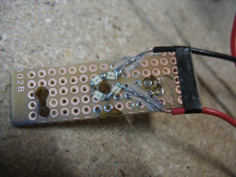
Here is the backside of that same plate. You can see the solder joints which you will need to de-solder and then re-solder your new LED's in place:

Display:
Blue: DA04-11PBWA/A
Yellow: DA04-11YWA
Red: DA04-11EWA
You need this standoff, or it'll look sunken in the CC unit:
DIP: DigiKey P/N: AE8916-ND
You need window tint to replace the factory green tint. Without the tint it's way too bright and will look super cheap. I got a big roll of tint from a local tint shop's scrap bin.
Interior Lighting
All bulbs here are awaiting confirmation. If one is incorrect, notify me via PM or post here.
Location_______________Bulb Type
**Bulb tpyes that I am CERTAIN of are in BOLD
Key ring _______________#74
Driver's footwell_________#74
Overhead lamp__________BA9
Cigarette lighter ________#74
Ash tray_______________#74
Driver's window switch___3mm (T1) x2
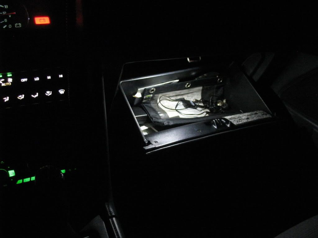
Glove box______________#74
Vanity Mirror___________#3022?
Door Panel_____________#3022
Hatch light ____________#3022
Exterior key ring ________ 2mmx5mm according to Ivan (iruyle)
Dash Buttons___________12V incandescent << Need to integrate resistors w/3mm led.
Total required:
Type_____QTY
#74______5
#3022____1 <-----Use High Power LED's if you want it to be any brighter than the stock bulb
BA9______2 <----Use High Power LED's if you want it to be any brighter than the stock bulbs
Changing the dash switch lighting is far from plug'n'play.
Here's how I did it:
-Remove switch from panel
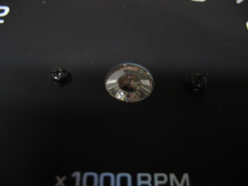
-Remove rocker part of switch (front face that you touch)
-Remove nasty green filter by punching out the part of the face that lights up. We'll call this the "icon".
Defroster filter shown below
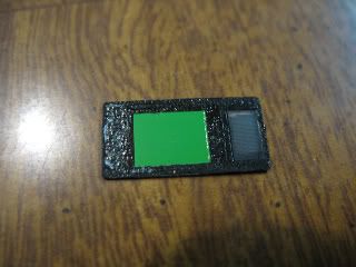
-Remove filter layer by prying the layers apart with a jewlers screwdriver or a razor.
-No more green. (Yes!)
-Replace icon with super glue or the like.
Swapping in LEDs:
Since the old bulb was incandescent and ran on 12V, we need to alter the voltage your new 3mm LED will see. This is accomplished via resistor(s).
Common 3mm led's will require something around 2-3V. Careful! Too much voltage/current will blow an LED immediately. For my white and red LED's I needed about 500 ohms resistance.
Use this equation; The resistor value, R is given by:
R = (VS - VL) / I
VS = supply voltage (12-14V)
VL = LED voltage (usually 2.7V, but 3-4V for blue and white LEDs, check your LED's spec sheet)
I = LED current (e.g. 20mA), this must be less than the maximum permitted
Easy, right? I hope so. If not, you may want to revisit high school math/physics.
Ok, so now you know what you need. Go to radioshack or any other electrons parts retailer and get some resistors. Time to solder...
Making the circuit within the switch:
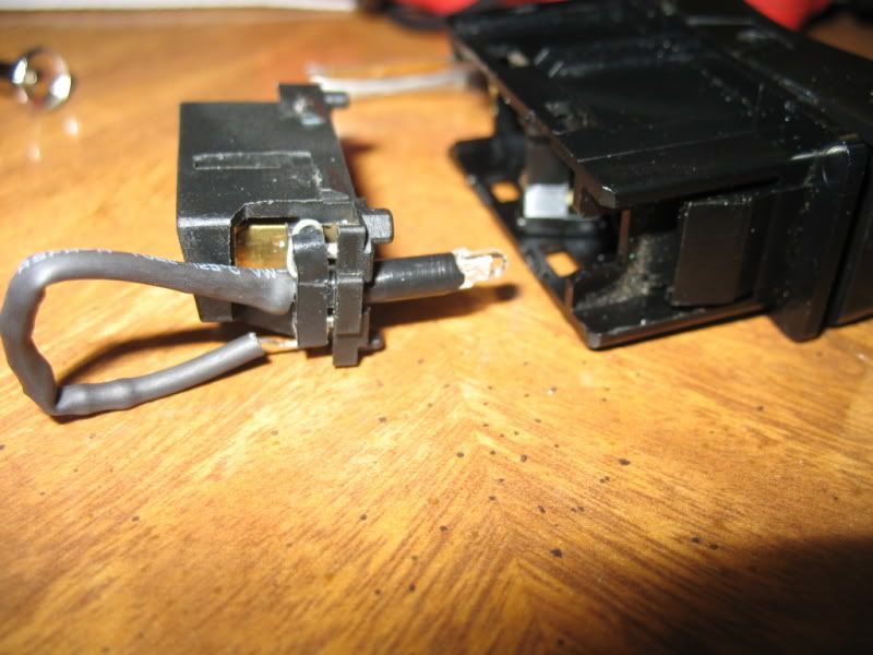
Remove the backing to the switch. It is snap fit and requires careful prying.
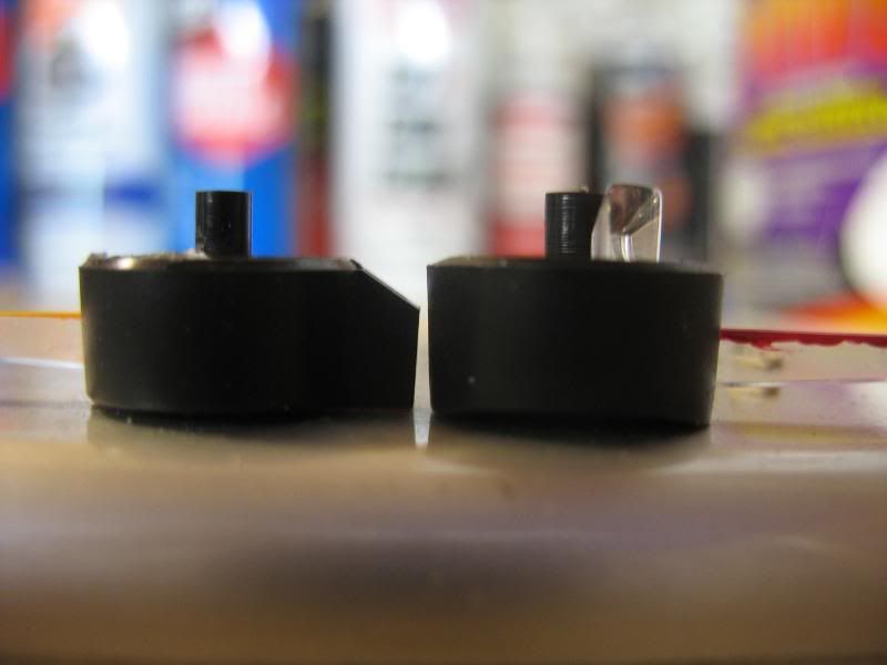
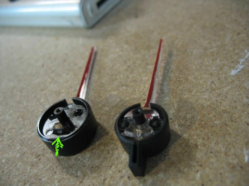
Remove old bulb from rubber socket. Notice how the light is fed with voltage.
Insert new LED into rubber socket.
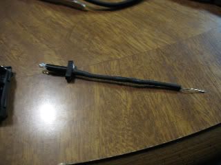
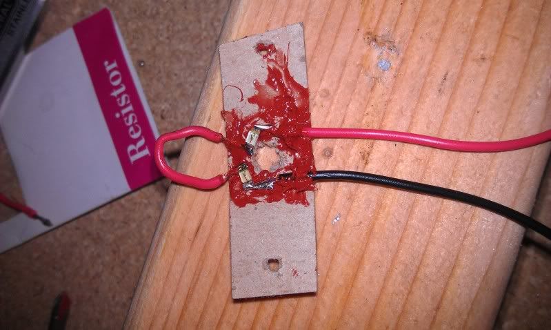
Cut the resistors down so only about ~1/2" of wire extends from the resistor. Now I needed to use two resistors in series to achieve my target resistance, so I needed to combine two.
Solder the resistors together and to the LED, making one lead of the LED really long. Use shrink insulation to enclose the wiring mess you made.
Like this:
Now you need to connect this to the other terminal of the rubber socket.
Insert back into switch panel. Test which way it needs to go. Only one way will light because LED's are polarized. Dur.
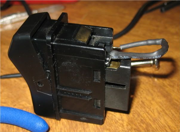
Done.
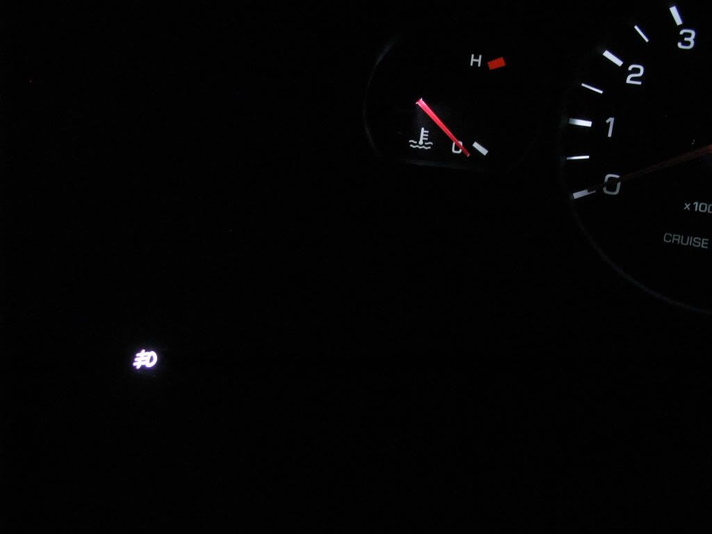
This was the fog switch, but I did the hazard and defroster the exact same way.
DRIVERS SIDE WINDOW SWITCH
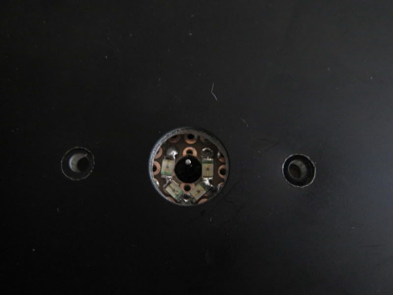
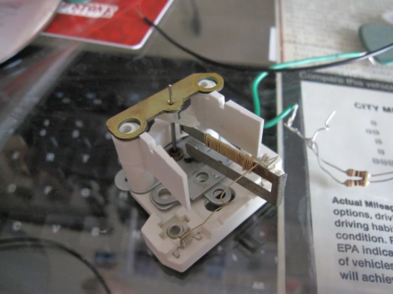
This is actually an easy one. Remove the window switch from the door handle. Disassemble the switch until you get here:
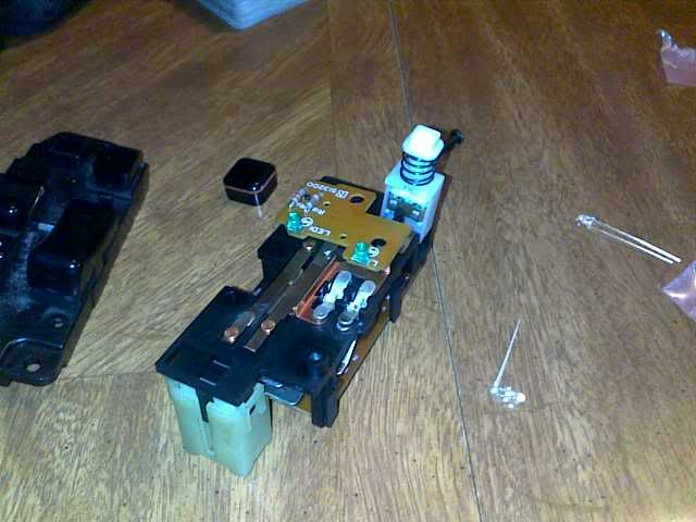
Now remove the tan circuit board. Desolder the LED's, then resolder in the new 3mm (T1) leds.
Mine ended up a little bright, but not distractingly so.
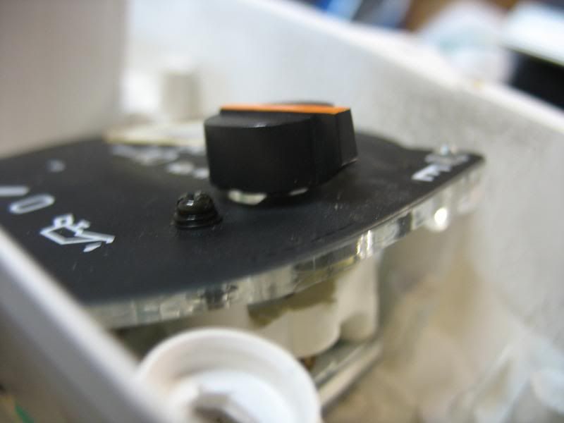
DIMMER wiring:
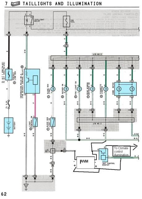
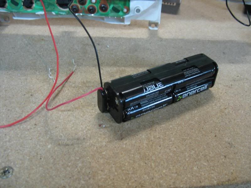
I wanted to have control over the climate control to get it a little closer to the dash lighting and THEN be able to control both together. I ran into a problem: The climate control uses a voltage regulator or some controller within itself that cuts out if the dimmer signal going in is adjusted either with a pwm or the regular dimmer. DAMN.
My current set-up is as shown above and allows me to control the climate control with the stock dimmer to dim it down to it's lowest point. From here I can dim the dash and the cc unit by using the PWM dimmer I bought from superbrightleds. This works well, but it'd be really nice to tap into the cc unit wiring. CRE had told me that he found the true dimming line within the cc unit, but I'll have to ask him to remind me of that wire.
Here's my current set-up:
Gauge Cluster Lighting
FROM THIS:
TO THIS:
Bulbs:
Type_____Qty
#194_____4
#74______1
Many members have used LED's from
_____194__________74______
Simply remove the old bulb and replace with a new LED bulb.
When using the 5 WLED bulbs the oil gauge may appear dimmer than the other gauges since the oil gauge is lit by only one #74. I solved this COMPLETELY by placing a small section of aluminum foil over the bulb, directing most all the light onto the gauge face and its clear plastic "light carrier".
Light dispersion is very important for the gauge cluster's appearance. "Hot spots", where lights can become focused, are your enemy. When using LED lights, hot spots can be a problem. This can be fixed by using "wide angle" LED lights. These lights put more light out the sides of the bulb and help to prevent hot spots. Using the 5 bulb LED's from superbrightled can lead to hotspots directly in front of the bulbs. (3 and 9 O'clock on the speedo and tach especially) I solved this by painting the tip of the top bulb black. Using just these bulbs will tend to make any painted needle appear dimmer. Beware.
Another method is to paint the incandescent bulbs. This is a cheap and relatively easy way to change the color, but care must be taken not to overcoat the bulbs making them too dim.
Climate Control Unit
Bulbs
29 - T1 (3mm)
13 for the indicators
16 for the buttons
Using the 3mm LED's from superbright made my climate control insanely bright. If I were to do this again, I would use an LED with a lesser MCD rating. Mine were rated at ~4500 mcd and that was way too much. Looks neat by itself, but it is blinding at night on a highway.
CC unit disassembled, showing the Temp display and the button lighting LED's:
Here is the backside of that same plate. You can see the solder joints which you will need to de-solder and then re-solder your new LED's in place:
Display:
Blue: DA04-11PBWA/A
Yellow: DA04-11YWA
Red: DA04-11EWA
You need this standoff, or it'll look sunken in the CC unit:
DIP: DigiKey P/N: AE8916-ND
You need window tint to replace the factory green tint. Without the tint it's way too bright and will look super cheap. I got a big roll of tint from a local tint shop's scrap bin.
Interior Lighting
All bulbs here are awaiting confirmation. If one is incorrect, notify me via PM or post here.
Location_______________Bulb Type
**Bulb tpyes that I am CERTAIN of are in BOLD
Key ring _______________#74
Driver's footwell_________#74
Overhead lamp__________BA9
Cigarette lighter ________#74
Ash tray_______________#74
Driver's window switch___3mm (T1) x2
Glove box______________#74
Vanity Mirror___________#3022?
Door Panel_____________#3022
Hatch light ____________#3022
Exterior key ring ________ 2mmx5mm according to Ivan (iruyle)
Dash Buttons___________12V incandescent << Need to integrate resistors w/3mm led.
Total required:
Type_____QTY
#74______5
#3022____1 <-----Use High Power LED's if you want it to be any brighter than the stock bulb
BA9______2 <----Use High Power LED's if you want it to be any brighter than the stock bulbs
Changing the dash switch lighting is far from plug'n'play.
Here's how I did it:
-Remove switch from panel
-Remove rocker part of switch (front face that you touch)
-Remove nasty green filter by punching out the part of the face that lights up. We'll call this the "icon".
Defroster filter shown below
-Remove filter layer by prying the layers apart with a jewlers screwdriver or a razor.
-No more green. (Yes!)
-Replace icon with super glue or the like.
Swapping in LEDs:
Since the old bulb was incandescent and ran on 12V, we need to alter the voltage your new 3mm LED will see. This is accomplished via resistor(s).
Common 3mm led's will require something around 2-3V. Careful! Too much voltage/current will blow an LED immediately. For my white and red LED's I needed about 500 ohms resistance.
Use this equation; The resistor value, R is given by:
R = (VS - VL) / I
VS = supply voltage (12-14V)
VL = LED voltage (usually 2.7V, but 3-4V for blue and white LEDs, check your LED's spec sheet)
I = LED current (e.g. 20mA), this must be less than the maximum permitted
Easy, right? I hope so. If not, you may want to revisit high school math/physics.
Ok, so now you know what you need. Go to radioshack or any other electrons parts retailer and get some resistors. Time to solder...
Making the circuit within the switch:
Remove the backing to the switch. It is snap fit and requires careful prying.
Remove old bulb from rubber socket. Notice how the light is fed with voltage.
Insert new LED into rubber socket.
Cut the resistors down so only about ~1/2" of wire extends from the resistor. Now I needed to use two resistors in series to achieve my target resistance, so I needed to combine two.
Solder the resistors together and to the LED, making one lead of the LED really long. Use shrink insulation to enclose the wiring mess you made.
Like this:
Now you need to connect this to the other terminal of the rubber socket.
Insert back into switch panel. Test which way it needs to go. Only one way will light because LED's are polarized. Dur.
Done.
This was the fog switch, but I did the hazard and defroster the exact same way.
DRIVERS SIDE WINDOW SWITCH
This is actually an easy one. Remove the window switch from the door handle. Disassemble the switch until you get here:
Now remove the tan circuit board. Desolder the LED's, then resolder in the new 3mm (T1) leds.
Mine ended up a little bright, but not distractingly so.
DIMMER wiring:
I wanted to have control over the climate control to get it a little closer to the dash lighting and THEN be able to control both together. I ran into a problem: The climate control uses a voltage regulator or some controller within itself that cuts out if the dimmer signal going in is adjusted either with a pwm or the regular dimmer. DAMN.
My current set-up is as shown above and allows me to control the climate control with the stock dimmer to dim it down to it's lowest point. From here I can dim the dash and the cc unit by using the PWM dimmer I bought from superbrightleds. This works well, but it'd be really nice to tap into the cc unit wiring. CRE had told me that he found the true dimming line within the cc unit, but I'll have to ask him to remind me of that wire.
Here's my current set-up:
Last edited:
")