How to Make a Leak Down Tester & Perform a Test

Status
Not open for further replies.

TONY!

Habitual Supra Killer
Mar 30, 2005
523
4
18
Tonyland
How to Make the Leak Down Tester

A leak down test is when compressed air is injected into the cylinders & reads how much the engine is leaking. Reasons why engines can excessively leak are from bad rings to cylinders sealing, damaged pistons or rings, poor valves to valve seats sealing, a blown head gasket, or even a cracked head or block.

There are a couple testers that can be used for this procedure. The one most people think of is the one with two gauges that can run about $170.00.

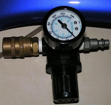
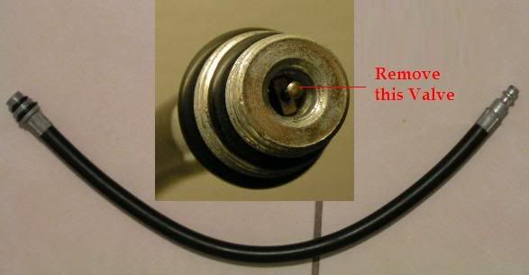
From surfing the net I found you can easily make your own & save $$$. If you already have a compression tester (the kind that includes the hose), all you would need is an air pressure gauge, an air line coupler, what they call a male fitting, and some Teflon tape. To use the hose that comes with the compression tester for leak down testing, you need to remove the valve that is within that hose. That valve is necessary for compression testing because without it, you won’t be able to see your readings as easily because it holds the pressure within the tester. Now for leak down testing, the air will be coming from the opposite direction (to the cylinder) so removing the valve is quite necessary. The cost should be about $20 if you know where to get the parts from and already have the threaded hose typed compression tester. If not, you can add about $25 for the compression tester or possibly make the hose (not sure how easy that is though).
p22566_1.jpg

p22566_2.jpg

If the photobucket.com pics don't download for you, try them individually.
http://img.photobucket.com/albums/v519/Tony9RR/leakdown.jpg
http://img.photobucket.com/albums/v519/Tony9RR/Hose.jpg
 

TONY!

Habitual Supra Killer
Mar 30, 2005
523
4
18
Tonyland
(1) Secure the car in place.
I like to place eight bricks snugly before & after each tire. The reason for this is because the compressed air will push the tested cylinder’s piston down. Securing the car this way keeps it from jumping forwards or backwards & also keeps the engine’s rotating assembly from turning.

(2) Make way for the testing.
Remove everything required to enable you to access the spark plug holes as you would with a spark plug change or a compression test.

(3) Put the transmission in neutral.
You need to do this enable the rotating assembly to spin for set up.

(4) Position cylinder No.1’s piston to TDC.
For the first cylinder you test (No.1), you will have the benefit of matching the crank pulley notch mark to the timing belt cover. This indicates TDC for cylinder No.1, but won’t necessarily mean that it is at TDC after the compression stroke (where you need to be).

(5) Check which TDC are at, and set to TDC at the height of the compression stroke.
There are two TDC positions in a four stroke engine. If you test at TDC after the exhaust stoke, you would be between the exhaust valves being open & the intake valves opening during the intake stroke. I test with the piston of the cylinder at TDC AFTER the compression stroke (which is right before the power stroke) because all the valves will be closed before & after this TDC position. If you should be slightly off at this position, your valves will still be closed and you also won’t have to worry about the cams being advanced or retarded & how that will affect your readings.

(a) With N/A models only (turbo models don’t have distributors) you can verify that you are at the correct TDC by looking at the distributor. If the rotor within it is aligned to the distributor’s cylinder No.1 contact, you are ready to proceed. If not & you are 180 degrees off, turn the crank pulley bolt one revolution & reset the notch on the crank pulley to zero according to the numbers on the timing case.

(b) If your cam gears are exposed, you can look at the positioning of their timing notch marks & check that they are in the 12 O’clock position. If cam gear notch marks are in the 6 O’clock position, turn the crank pulley bolt one revolution & reset the notch on the crank pulley to zero according to the numbers on the timing case.

(c) Another way to determine if you are at the height of the compression stoke rather than the exhaust stroke is to turn the crank bolt a slight bit counter-clockwise & test to see how much air you are leaking (further steps needed to test are described below). If you are losing a lot of air (beyond 25%), then the exhaust valves are probably open as you may be in the exhaust stroke rather than the compression stroke. If you are losing an excess amount of air you need to turn the crank one revolution & set the notch on the crank pulley to zero according to the numbers on the timing case.

(6) Put it in gear to lock the piston in place.
After you figured out where TDC is after the compression stroke for the cylinder being tested, put the transmission in gear to lock the rotating assembly in place while testing. If left in neutral, the piston will just drop; the rotating assembly needs to be held in place, so putting it in gear is a must.

(7) Connect the tester’s hose to the spark plug hole.
Take the hose of a compression tester (with the valve removed) & thread it into the cylinder’s spark plug hole as you would for a compression test.

(8) Snap the gauge of the tester to the compressed air line coming out of the compressor.

(9) Adjust the air gauge of the tester to read 100PSI when hooked to the air line coming from the compressor.

(10) Now all you have to do is snap the leak down tester to the compression tester’s hose to get your reading. The difference between the reading you get now & the 100PSI you started with (the available pressure) is your leak. So if the gauge reads 90PSI, 10% would be your leak for that cylinder. Record your reading and disconnect the tester, air line & hose from the car.

(11) Let’s set up for the next cylinder. Put the transmission in neutral as in step 3.

(12) One way to determine how much you have to turn the crank in order to set up and test the next cylinder in the firing order, is to wrap tape around the 19mm socket (that you are using to turn the crank bolt) & then mark the tape on the socket at 0, 120, 240 degrees, as you will be turning it in those increments. There are 720 degrees of rotation for the crank to complete one cycle in a four stroke motor; 360 degrees for the cams. 720 divided by 6 (# of cylinders) is 120. So 120 degrees clockwise is the amount you need to spin the crank bolt to test the next cylinder. Turn the crank bolt 120 degrees clockwise.
Just make sure you keep the socket in place so that you can keep track of how much you are turning it for each cylinder.

Testing order/Firing order:153624--Easily derived by observing the sequence of my cam lobes.

I like to double check & fine tune to make sure I am at the highest piston position & in fact at TDC next. The way I do this is by placing an 8 inch or so rod that is thin enough to go through the spark plug holes (I used a section of an antenna). The bottom of the rod will be resting on the piston tops. When you turn the crank & the rod reaches its highest point, you are at TDC. I like to wrap tape around the rod where it meets the top of the head at the rod’s highest position. This serves as a point of reference of how much you have to turn or how close you are to TDC for the remaining cylinders since you can’t use the timing cover’s markings other than for cylinder No.1.

13) Repeat steps 6-12 for the remaining cylinders in the firing order mentioned (153624).
 
Status
Not open for further replies.